1998 JAGUAR X308 exhaust
[x] Cancel search: exhaustPage 1134 of 2490
Intake Air Distribution and Filtering - Thrott
le Body Elbow
Re
mo
val and Installation
Remov
a
l
1.
WARNING: B E
FORE PROCEEDING, IT IS ESSENTIAL THAT
WARNING NOTES GIVEN IN SECTION 100-00 (UNDER HEADING
'SAFETY PRECAUTIONS') AR E READ AND UNDERSTOOD.
Disconnect battery ground cable (IMPORTANT, see SRO
86.15.19 for further information).
2. Re
move air cleaner cover / inta
ke assembly; refer 19.10.30.
3. Remove throttle assemb ly; refer to 19.70.04.
4. Remove exhaust gas recirculation (EGR) valve where installed;
refer 17.45.01.
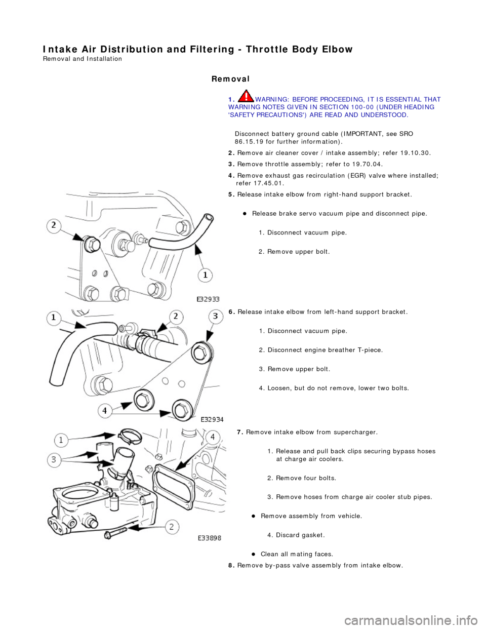
5. Re
lease intake elbow from right-hand support bracket.
Re
lea
se brake servo vacuum pi
pe and disconnect pipe.
1. Disconnect vacuum pipe.
2. Remove upper bolt.
6. Relea
se intake elbow from le
ft-hand support bracket.
1. Disconnect vacuum pipe.
2. Disconnect engine breather T-piece.
3. Remove upper bolt.
4. Loosen, but do not remove, lower two bolts.
7. Re
move intake elbow from supercharger.
1. Release and pull back cl ips securing bypass hoses
at charge air coolers.
2. Remove four bolts.
3. Remove hoses from charge air cooler stub pipes.
Re move as
sembly from vehicle.
4. Discard gasket.
Cle a
n all mating faces.
8. Remove by-pass valve assembly from intake elbow.
Page 1136 of 2490
2.
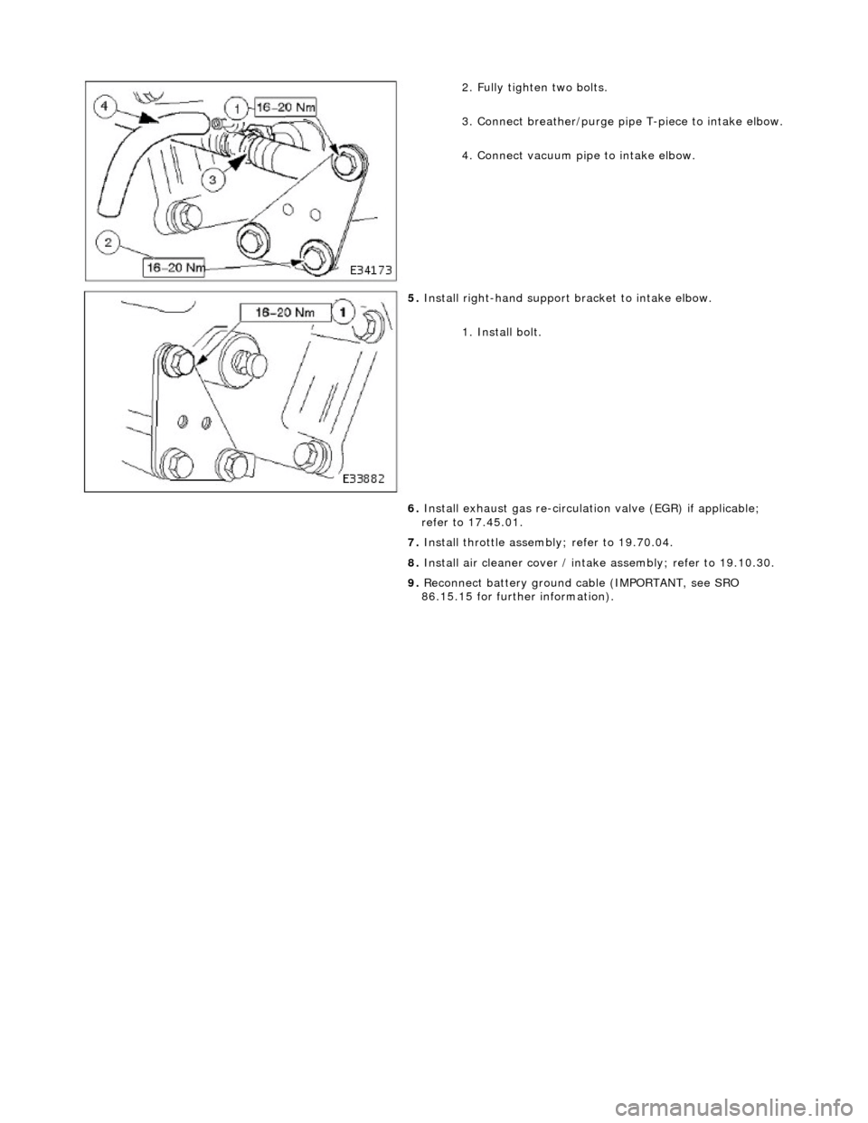
Fully tighten two bolts.
3. Connect breather/purge pipe T-piece to intake elbow.
4. Connect vacuum pipe to intake elbow.
5. Install right-hand support brac
ket to intake elbow.
1. Install bolt.
6. Install exhaust gas re-circulation valve (EGR) if applicable;
refer to 17.45.01.
7. Install throttle assemb ly; refer to 19.70.04.
8. Install air cleaner cover / intake assembly; refer to 19.10.30.
9. Reconnect battery ground cable (IMPORTANT, see SRO
86.15.15 for further information).
Page 1142 of 2490
Intake Air Distribution and Filtering - Throttle B
ody Elbow4.0L SC V8 -
AJ26
Re mo
val and Installation
Remova
l
1.
WARNING: BE
FORE PROCEEDING, IT IS ESSENTIAL THAT
WARNING NOTES GIVEN IN SECTION 100-00 (UNDER HEADING
'SAFETY PRECAUTIONS') AR E READ AND UNDERSTOOD.
Disconnect battery ground cable (IMPORTANT, see SRO
86.15.19 for further information).
2. Re
move air cleaner cover / inta
ke assembly; refer 19.10.30.
3. Remove throttle assemb ly; refer to 19.70.04.
4. Remove exhaust gas recirculation (EGR) valve where installed;
refer 17.45.01.
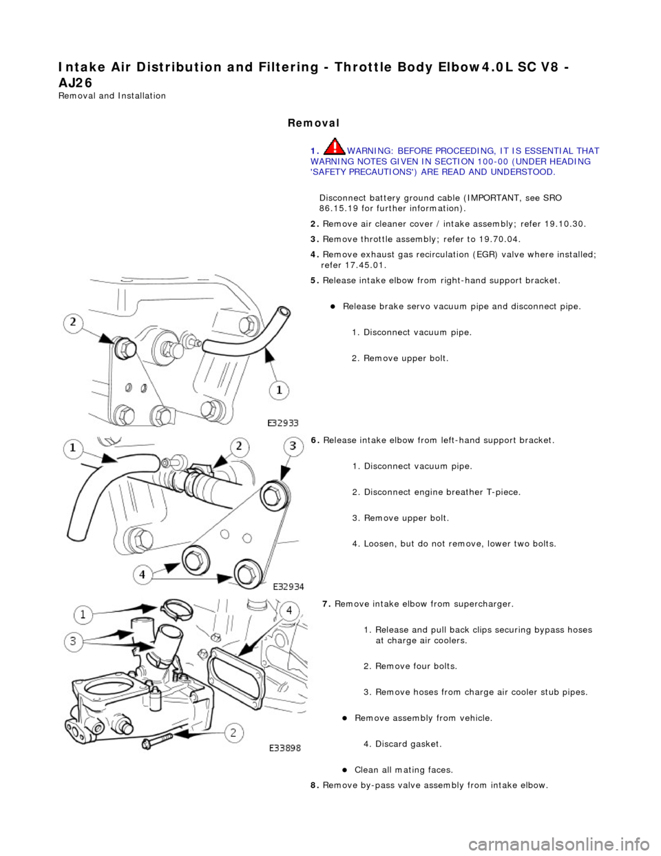
5. Re
lease intake elbow from right-hand support bracket.
Re
lea
se brake servo vacuum pi
pe and disconnect pipe.
1. Disconnect vacuum pipe.
2. Remove upper bolt.
6. Relea
se intake elbow from le
ft-hand support bracket.
1. Disconnect vacuum pipe.
2. Disconnect engine breather T-piece.
3. Remove upper bolt.
4. Loosen, but do not remove, lower two bolts.
7. Re
move intake elbow from supercharger.
1. Release and pull back cl ips securing bypass hoses
at charge air coolers.
2. Remove four bolts.
3. Remove hoses from charge air cooler stub pipes.
Re move as
sembly from vehicle.
4. Discard gasket.
Cle a
n all mating faces.
8. Remove by-pass valve assembly from intake elbow.
Page 1144 of 2490
2.
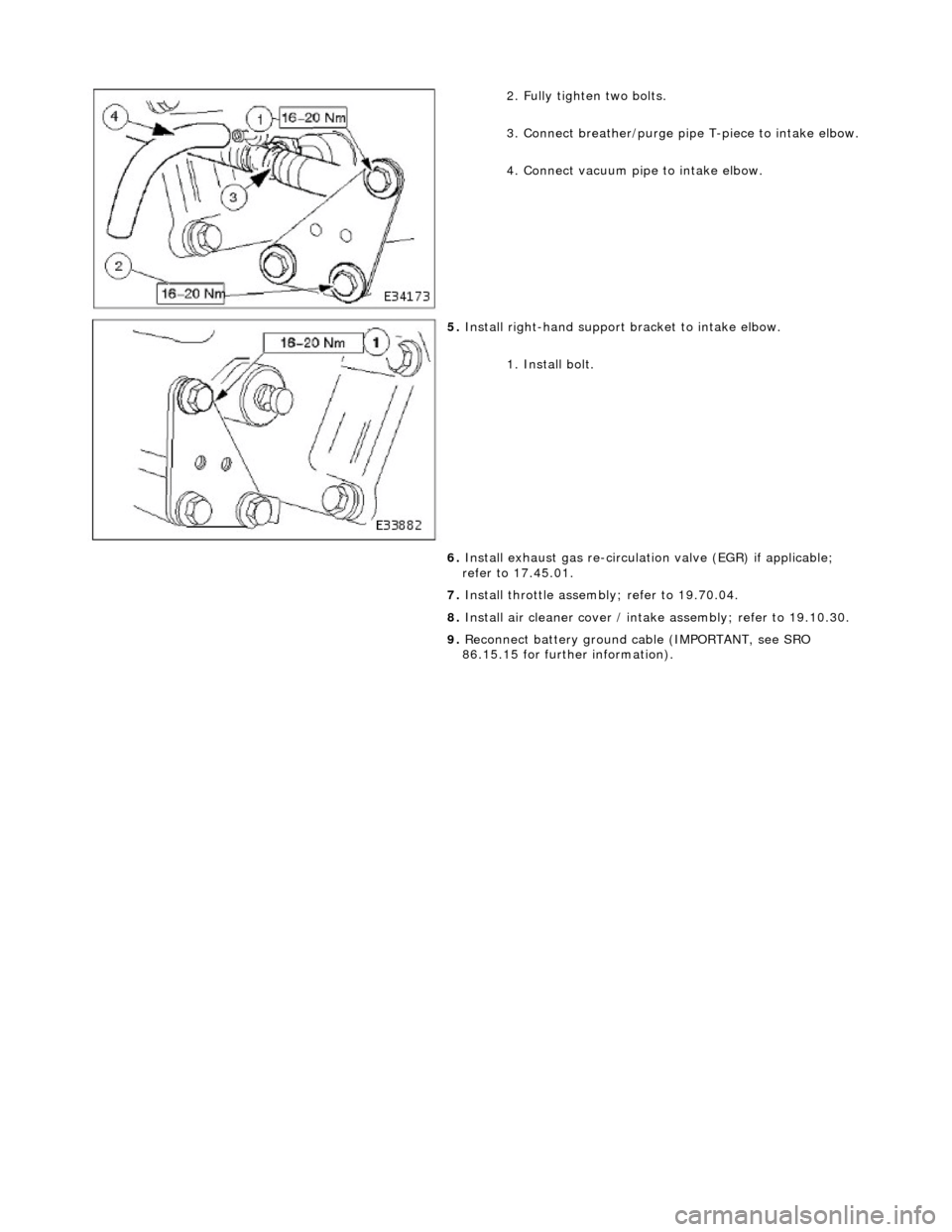
Fully tighten two bolts.
3. Connect breather/purge pipe T-piece to intake elbow.
4. Connect vacuum pipe to intake elbow.
5. Install right-hand support brac
ket to intake elbow.
1. Install bolt.
6. Install exhaust gas re-circulation valve (EGR) if applicable;
refer to 17.45.01.
7. Install throttle assemb ly; refer to 19.70.04.
8. Install air cleaner cover / intake assembly; refer to 19.10.30.
9. Reconnect battery ground cable (IMPORTANT, see SRO
86.15.15 for further information).
Page 1179 of 2490
generates a signal when th
e dr
ive plate passes the sensor
sen
ds the ECM signals indicating crankshaft position and engine speed
is e
ssential for calculating spark timing
En
gine Coolant Temperature (ECT) Sensor
sen
ds the ECM a signal indicating the temperature of the engine coolant
is a t
emperature dependent resistor with a negative temperature coefficient (resistance changes inversely with
respect to temperature) and is constantly monitored by the ECM
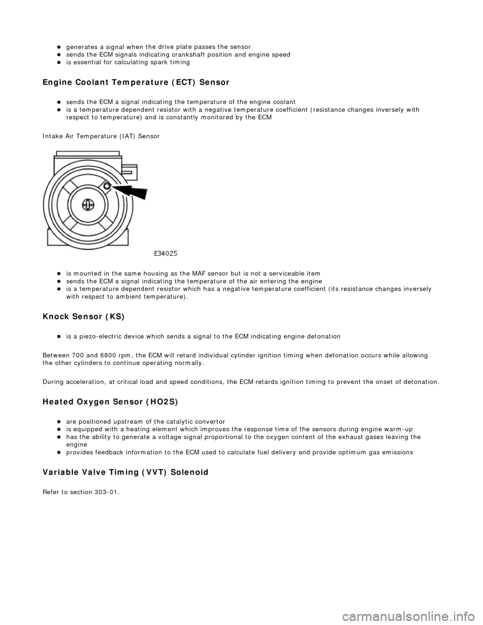
Intake Air Temperature (IAT) Sensor
is m
ounted in the same housing as the MA
F sensor but is not a serviceable item
sen
ds the ECM a signal indicating the temperature of the air entering the engine
is a t
emperature dependent resistor which has a negative
temperature coefficient (its resistance changes inversely
with respect to ambient temperature).
Knock S
ensor (KS)
is a pi
ezo-electric device which sends a signal
to the ECM indicating engine detonation
Between 700 and 6800 rpm, the ECM will retard individual cylinder ignition timing when detonation occurs while allowing
the other cylinders to continue operating normally.
During acceleration, at critical load and speed conditions, the ECM retards ignition timing to prevent the onset of detonation.
H
eated Oxygen Sensor (HO2S)
are
positioned upstream of the catalytic convertor
is equipped with
a heating element wh
ich improves the response time of the sensors during engine warm-up
h
as the ability to generate a voltage signal proportional to the oxygen content of the exhaust gases leaving the
engine
pr
ovides feedback information to the ECM used to calc
ulate fuel delivery and provide optimum gas emissions
Variable V
alve Timing (VVT) Solenoid
R
efer to section 303-01.
Page 1196 of 2490
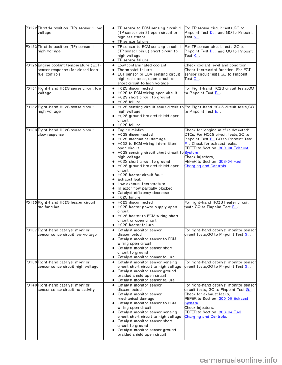
P0122Throttle
position (TP) sensor 1 low
voltage
TP se ns
or to ECM sensing circuit 1
(TP sensor pin 3) open circuit or
high resistance
TP sensor fail
ure
F
o
r TP sensor circ
uit tests,GO to
Pinpoint Test D.
, and GO
to Pinpoint
Test K.
.
P0123Throttl e
position (TP) sensor 1
high voltage
TP se ns
or to ECM sensing circuit 1
(TP sensor pin 3) short circuit to
high voltage
TP sensor fail
ure
F
o
r TP sensor circ
uit tests,GO to
Pinpoint Test D.
, and GO
to Pinpoint
Test K.
.
P0125En
gine coolant temperature (ECT)
sensor response (for closed loop
fuel control)
Low/contaminated coolant Therm o
stat failure
ECT se
ns
or to ECM sensing circuit
high resistance, open circuit or
short circuit to high voltage
Che c
k coolant level and condition.
Check thermostat function. For ECT
sensor circuit tests,GO to Pinpoint
Test C.
.
P0131Right -
hand H02S sense circuit low
voltage
H02 S
disconnected
H0
2S to
ECM wiring open circuit
H0
2S short ci
rcuit to ground
H0
2S fail
ure
F
or R
ight-hand HO2S circuit tests,GO
to Pinpoint Test E.
.
P0132Right-
hand H02S sense circuit
high voltage
H02 S
sensing circuit short circuit to
high voltage
H0 2S groun
d braided shield open
circuit
H0 2S fail
ure
F
or R
ight-hand HO2S circuit tests,GO
to Pinpoint Test E.
.
P0133Right-
hand H02S sense circuit
slow response
Engine m
isfire
H02
S
disconnected
H0
2S mechanical damage
H0
2S to
ECM wiring intermittent
open circuit
H02 S
sensing circuit short circuit to
high voltage
H02S short ci
rcuit to ground
H02S groun
d braided shield open
circuit
H0 2S heater circuit faul
t
Exhaus
t leak
Low e
x
haust temperature
Injector fl
ow parti
ally blocked
Catal
y
st efficiency decrease
H0
2S fail
ure
Chec
k for 'en
gine misfire detected'
DTCs. For HO2S circuit tests,GO to
Pinpoint Test E.
.G
O to Pinpoint Test
F.
. Check for exhaust leaks,
REF
ER to Section 309
-00
Ex
haust
Sy
ste
m
.
Chec k inje
ctors,
REFER to Section 303
-04 Fu
el
Charging and Cont
rols
.
P0135Right
-
hand H02S heater circuit
malfunction
H02 S
disconnected
H0
2S h
eater power supply open
circuit
H0 2S heater to ECM wi
ring short
circuit or open circuit
H0 2S heater fai
lure
F
o
r right-hand HO2S heater circuit
tests,GO to Pinpoint Test F.
.
P0137Right-
hand catalyst monitor
sensor sense circuit low voltage
Catal y
st monitor sensor
disconnected
Catal y
st monitor sensor to ECM
wiring open circuit
Catal y
st monitor sensor short
circuit to ground
Cat a
lyst monitor sensor failure
F
or ri
ght-hand catalyst monitor sensor
circuit tests,GO to Pinpoint Test G.
.
P0138Right -
hand catalyst monitor
sensor sense circuit high voltage
Catal y
st monitor sensor sensing
circuit short circuit to high voltage
Catalyst
monitor sensor ground
braided shield open circuit
Cata
lyst monitor sensor failure
F
or ri
ght-hand catalyst monitor sensor
circuit tests,GO to Pinpoint Test G.
.
P0140Right -
hand catalyst monitor
sensor sense circuit no activity
Catal y
st monitor sensor
disconnected
Catal y
st monitor sensor
mechanical damage
Catal y
st monitor sensor to ECM
wiring open circuit
Catal y
st monitor sensor sensing
circuit short circuit to high voltage
Cataly
st monitor sensor short
circuit to ground
Catalyst
monitor sensor ground
braided shield open circuit
F or ri
ght-hand catalyst monitor sensor
circuit tests, GO to Pinpoint Test G.
.
Check f o
r exhaust leaks,
REFER to Section 309
-00 Ex
haust
Sy
ste
m
.
Chec k inje
ctors,
REFER to Section 303
-04 Fu
el
Charging and Con
t
rols
.
Page 1197 of 2490
Exhaus
t leak
Low e
xhaust temperature
Cat
alyst monitor sensor failure
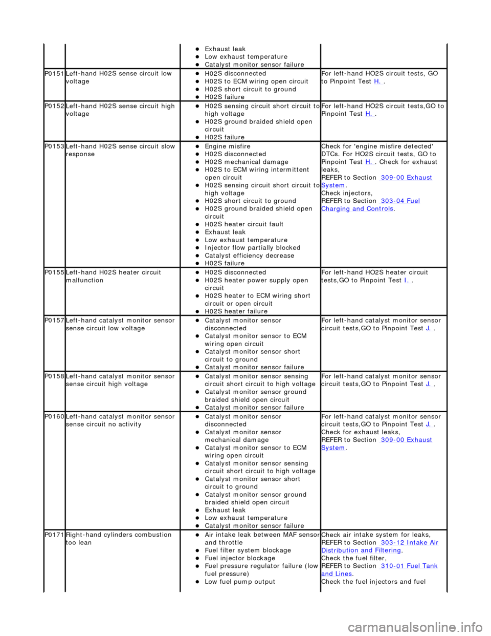
P0151Le
ft-hand H02S sense circuit low
voltage
H02
S disconnected
H0
2S to ECM wiring open circuit
H0
2S short circuit to ground
H0
2S failure
F
or left-hand HO2S circuit tests, GO
to Pinpoint Test H.
.
P0152Le
ft-hand H02S sense circuit high
voltage
H02
S sensing circuit short circuit to
high voltage
H0
2S ground braided shield open
circuit
H0
2S failure
F
or left-hand HO2S circuit tests,GO to
Pinpoint Test H.
.
P0153Le
ft-hand H02S sense circuit slow
response
Engine
misfire
H02
S disconnected
H0
2S mechanical damage
H0
2S to ECM wiring intermittent
open circuit
H02
S sensing circuit short circuit to
high voltage
H0
2S short circuit to ground
H0
2S ground braided shield open
circuit
H0
2S heater circuit fault
Exhaus
t leak
Low e
xhaust temperature
Injector fl
ow partially blocked
Catal
yst efficiency decrease
H0
2S failure
Chec
k for 'engine misfire detected'
DTCs. For HO2S circ uit tests, GO to
Pinpoint Test H.
. Check for exhaust
leak
s,
REFER to Section 309
-00
Exhaust
Sy
stem
.
Chec
k injectors,
REFER to Section 303
-04
Fuel
Charging and Con
trols
.
P0155Left-hand H02S heater
circuit
malfunction
H02
S disconnected
H0
2S heater power supply open
circuit
H0
2S heater to ECM wiring short
circuit or open circuit
H0
2S heater failure
F
or left-hand HO2S heater circuit
tests,GO to Pinpoint Test I.
.
P0157Le
ft-hand catalyst monitor sensor
sense circuit low voltage
Catal
yst monitor sensor
disconnected
Catal
yst monitor sensor to ECM
wiring open circuit
Catal
yst monitor sensor short
circuit to ground
Cat
alyst monitor sensor failure
F
or left-hand catalyst monitor sensor
circuit tests,GO to Pinpoint Test J.
.
P0158Le
ft-hand catalyst monitor sensor
sense circuit high voltage
Catal
yst monitor sensor sensing
circuit short circuit to high voltage
Catalyst
monitor sensor ground
braided shield open circuit
Cat
alyst monitor sensor failure
F
or left-hand catalyst monitor sensor
circuit tests,GO to Pinpoint Test J.
.
P0160Le
ft-hand catalyst monitor sensor
sense circuit no activity
Catal
yst monitor sensor
disconnected
Catal
yst monitor sensor
mechanical damage
Catal
yst monitor sensor to ECM
wiring open circuit
Catal
yst monitor sensor sensing
circuit short circuit to high voltage
Catal
yst monitor sensor short
circuit to ground
Catalyst
monitor sensor ground
braided shield open circuit
Exhaus
t leak
Low e
xhaust temperature
Cat
alyst monitor sensor failure
F
or left-hand catalyst monitor sensor
circuit tests,GO to Pinpoint Test J.
.
Check f
or exhaust leaks,
REFER to Section 309
-00
Exhaust
Sy
stem
.
P0171Right
-hand cylinders combustion
too lean
Air
intake leak between MAF senso
r and th
rottle
F
uel filter system blockage
F
uel injector blockage
F
uel pressure regulator failure (low
fuel pressure)
Low f
uel pump output
Check ai
r intake system for leaks,
REFER to Section 303
-1
2 Intake Air
Distribu
tion and Filtering
.
Check the fuel fi
lter,
REFER to Section 310
-01
Fuel Tank
and Lines.
Chec
k the fuel injectors and fuel
Page 1198 of 2490
H02S harness wiri
ng fault
E
x
haust leak (before catalyst)
ECM receivi
n
g incorrect signal from
one or more of the following
sensors - ECT, MAF, IAT, TP
pr essure regulator,
REF
ER to Section 303
-04
Fu
el
Charging and Con
t
rols
.
Chec k the
fuel pressure. Check the
exhaust system for leaks,
REFER to Section 309
-00 Ex
haust
Sy
ste
m
.
R e
fer to pinpoint tests for sensors
listed.
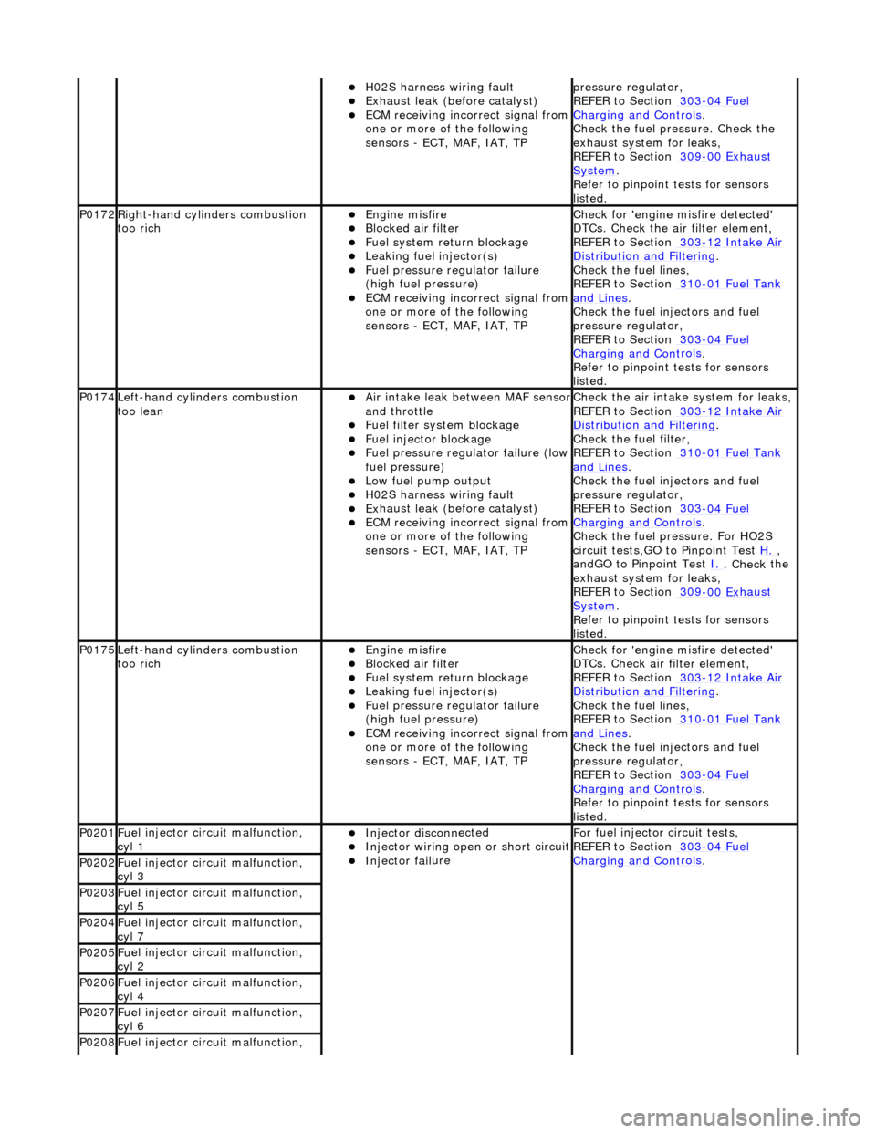
P0172Right -
hand cylinders combustion
too rich
Engine m
isfire
Bl
ocked air
filter
F
u
el system return blockage
Leak
i
ng fuel injector(s)
F
u
el pressure regulator failure
(high fuel pressure)
ECM receivi n
g incorrect signal from
one or more of the following
sensors - ECT, MAF, IAT, TP
Chec k for 'en
gine misfire detected'
DTCs. Check the air filter element,
REFER to Section 303
-1 2
Intake Air
Distribu
tion and Filterin
g
.
Chec k the
fuel lines,
REFER to Section 310
-01 Fu
el Tank
and Lines.
Chec k the
fuel injectors and fuel
pressure regulator,
REFER to Section 303
-04 Fu
el
Charging and Con
t
rols
.
R e
fer to pinpoint tests for sensors
listed.
P0174L e
ft-hand cylinders combustion
too lean
Air in
take leak between MAF senso
r and th
ro
ttle
F
u
el filter system blockage
F
u
el injector blockage
F
u
el pressure regulator failure (low
fuel pressure)
Low fu
el pump output
H0
2S harness wiri
ng fault
E
x
haust leak (before catalyst)
ECM receivi
n
g incorrect signal from
one or more of the following
sensors - ECT, MAF, IAT, TP
Check the ai r intak
e system for leaks,
REFER to Section 303
-1 2
Intake Air
Distribu
tion and Filterin
g
.
Check the fuel fi lter,
REF
ER to Section 310
-01
Fu
el Tank
and Lines.
Chec k the
fuel injectors and fuel
pressure regulator,
REFER to Section 303
-04 Fu
el
Charging and Con
t
rols
.
Chec k the
fuel pressure. For HO2S
circuit tests,GO to Pinpoint Test H.
,
a n
dGO to Pinpoint Test
I.
. Check
the
exhaust system for leaks,
REFER to Section 309
-00 Ex
haust
Sy
ste
m
.
R e
fer to pinpoint tests for sensors
listed.
P0175L e
ft-hand cylinders combustion
too rich
Engine m
isfire
Bl
ocked air
filter
F
u
el system return blockage
Leak
i
ng fuel injector(s)
F
u
el pressure regulator failure
(high fuel pressure)
ECM receivi n
g incorrect signal from
one or more of the following
sensors - ECT, MAF, IAT, TP
Chec k for 'en
gine misfire detected'
DTCs. Check air filter element,
REFER to Section 303
-1 2
Intake Air
Distribu
tion and Filterin
g
.
Chec k the
fuel lines,
REFER to Section 310
-01 Fu
el Tank
and Lines.
Chec k the
fuel injectors and fuel
pressure regulator,
REFER to Section 303
-04 Fu
el
Charging and Cont
rols
.
Re
fer to pinpoint tests for sensors
listed.
P0201 Fu
el injector circuit malfunction,
cyl 1
Injector discon n
ected
Inject
or wir
ing open or short circuit
Injector fail
ure
F
o
r fuel injector
circuit tests,
REFER to Section 303
-04 Fu
el
Charging and Con
t
rols
. P0202F
u
el injector circuit malfunction,
cyl 3
P0203F u
el injector circuit malfunction,
cyl 5
P0204F u
el injector circuit malfunction,
cyl 7
P0205F u
el injector circuit malfunction,
cyl 2
P0206F u
el injector circuit malfunction,
cyl 4
P0207F u
el injector circuit malfunction,
cyl 6
P0208F u
el injector circuit malfunction,