Page 881 of 2490

15. Loosen the bolt which secures the VVT unit.
Do not tamper with the three bolts which secure the VVT
mechanism to the sprockets. It is sealed at the factory to
the correct valve timing specif ication for the engine and is
supplied only as a complete unit.
16. Remove the primary chain tens ioner. Refer to operation
12.65.55, in this Section.
17. Remove the primary ch ain tensioner blade.
1. Remove the pivot bolt which secures the tensioner blade.
2. Remove the tensioner blade.
18. Reposition the VVT unit along the cam journal to allow the
chain to clear the head casting.
Disconnect the primary chain from the VVT unit and
reposition it against the crankshaft sprocket.
19. Remove the VVT unit.
1. Remove the securing bolt from the VVT unit and the exhaust cam sprocket.
2. Remove the VVT unit, exhaust sprocket and secondary chain as an asse mbly (release the chain
from the tensioner which is still secured to the
cylinder head).
Remove the secondary chain from the VVT unit and the
sprocket.
Page 882 of 2490

Installation
20. Clean and inspect all relevant components.
1. Push the tensioner piston (secon dary chain) into the body to
provide clearance for fitting.
1. Insert a thin rigid wire th rough the hole in the end of
the tensioner piston to displace the ball from the non-
return valve seat.
2. With the wire in position, press the piston fully into the tensioner body.
Remove the wire.
2. Fit the VVT unit to the engine.
Assemble the VVT unit, the exhaust camshaft sprocket
and the secondary chain, in pr eparation for fitting to the
engine.
1. Fit the above assembly to the camshafts with the chain correctly positioned over the tensioner; VVT
unit to the inlet and the sprocket to the exhaust.
2. Fit, but do not tighten, each bolt which secures the VVT unit and the exhaust sprocket to the camshafts.
Allow the VVT unit sufficien t space to fit the primary
chain, in a la ter operation.
3. Fit the chain tensioning tool 303 - 532 to the exhaust camshaft
sprocket.
Reposition the sprocket (and the VVT unit) for the most
advantageous position for use of the tool.
Remove the tool.
4. Refit the primary timing chain.
1. Lift the primary chain an d position it over the VVT
unit sprocket (the VVT unit mu st be pulled forward to
clear the cylinder head casting). There must be no
slack on the drive side of the primary chain and the
VVT unit must not be rotated on the camshaft.
2. Slide the VVT unit fully on to the camshaft.
5. Fit the primary chain tensioner blade.
1. Position the tensioner blade to the cylinder block.
Page 883 of 2490

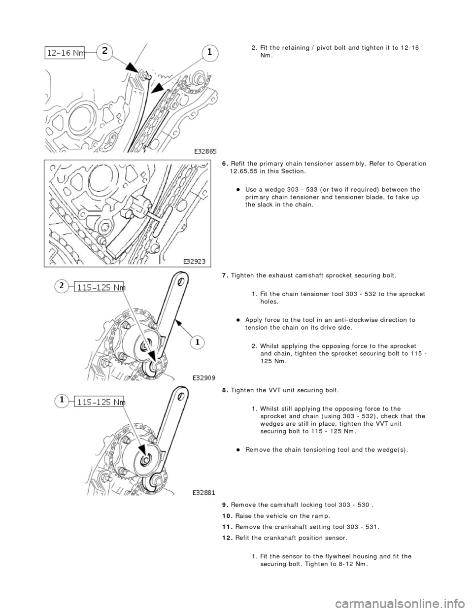
2. Fit the retaining / pivot bolt and tighten it to 12-16 Nm.
6. Refit the primary chain tensione r assembly. Refer to Operation
12.65.55 in this Section.
Use a wedge 303 - 533 (or two if required) between the
primary chain tensioner and te nsioner blade, to take up
the slack in the chain.
7. Tighten the exhaust camshaft sprocket securing bolt.
1. Fit the chain tensioner tool 303 - 532 to the sprocket holes.
Apply force to the tool in an anti-clockwise direction to
tension the chain on its drive side.
2. Whilst applying the opposing force to the sprocket and chain, tighten the sprock et securing bolt to 115 -
125 Nm.
8. Tighten the VVT unit securing bolt.
1. Whilst still applying the opposing force to the
sprocket and chain (using 303 - 532), check that the
wedges are still in place, tighten the VVT unit
securing bolt to 115 - 125 Nm.
Remove the chain tensioning tool and the wedge(s).
9. Remove the camshaft locking tool 303 - 530 .
10. Raise the vehicle on the ramp.
11. Remove the crankshaft setting tool 303 - 531.
12. Refit the crankshaft position sensor.
1. Fit the sensor to the fl ywheel housing and fit the
securing bolt. Tighten to 8-12 Nm.
Page 887 of 2490

Installation
15. Remove the primary ch ain tensioner blade.
1. Remove the pivot bolt which secures the tensioner blade.
2. Remove the tensioner blade.
16. Disconnect the primary chain from the VVT unit and the
crankshaft sprocket, and remove it completely.
17. Do not tamper with the three bolts which secure the VVT
mechanism to the sprockets. It is sealed at the factory to the
correct valve timing specificatio n for the engine and is supplied
only as a complete unit.
18. Remove the VVT unit.
1. Remove the securing bolt from both the VVT unit and
the exhaust cam sprocket.
2. Remove the VVT unit, exhaust sprocket and secondary chain as an asse mbly (release the chain
from the tensioner which is still secured to the
cylinder head).
Remove the secondary chain from the VVT unit and the
sprocket.
19. Clean and inspect all relevant components.
1. Push the tensioner piston (secon dary chain) into the body to
provide clearance for fitting.
1. Insert a thin rigid wire th rough the hole in the end of
the tensioner piston to displace the ball from the non-
return valve seat.
2. With the wire in position, press the piston fully into the tensioner body.
Remove the wire.
2. Fit the VVT unit to the engine.
Assemble the VVT unit, the exhaust camshaft sprocket
and the secondary chain, in pr eparation for fitting to the
engine.
1. Fit the above assembly to the camshafts with the chain correctly positioned over the tensioner; VVT
unit to the inlet and the sprocket to the exhaust.
2. Fit, but do not tighten, each bolt which secures the VVT unit and the exhaust sprocket to the camshafts.
Page 888 of 2490
3. Fit the chain tensioning tool 303 - 532 to the exhaust camshaft
sprocket.
Reposition the sprocket (and the VVT unit) for the most
advantageous position for use of the tool.
Remove the tool.
4. Refit the primary timing chain.
1. Fit the primary chain to position over the crankshaft sprocket and the VVT unit sprocket. There must be no
slack on the drive side of the primary chain.
2. The VVT unit must not be rotated on the camshaft
5. Fit the primary chain tensioner blade.
1. Position the tensioner blade to the cylinder block.
2. Fit the retaining / pivot bolt and tighten it to 12-16 Nm.
6. Refit the primary chain tensione r assembly. Refer to Operation
12.65.54 in this Section.
Use a wedge 303 - 533 (or two if required) between the
primary chain tensioner and te nsioner blade, to take up
the slack in the chain.
Page 889 of 2490

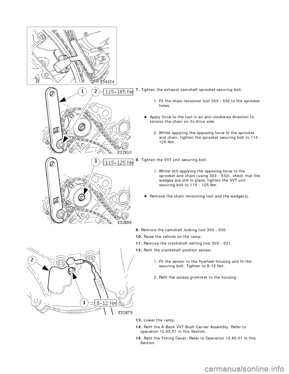
7. Tighten the exhaust camshaft sprocket securing bolt.
1. Fit the chain tensioner tool 303 - 532 to the sprocket holes.
Apply force to the tool in an anti-clockwise direction to
tension the chain on its drive side.
2. Whilst applying the opposing force to the sprocket and chain, tighten the sprock et securing bolt to 115 -
125 Nm.
8. Tighten the VVT unit securing bolt.
1. Whilst still applying the opposing force to the
sprocket and chain (using 303 - 532), check that the
wedges are still in place, tighten the VVT unit
securing bolt to 115 - 125 Nm.
Remove the chain tensioning tool and the wedge(s).
9. Remove the camshaft locking tool 303 - 530.
10. Raise the vehicle on the ramp.
11. Remove the crankshaft setting tool 303 - 531.
12. Refit the crankshaft position sensor.
1. Fit the sensor to the fl ywheel housing and fit the
securing bolt. Tighten to 8-12 Nm.
2. Refit the access grommet to the housing.
13. Lower the ramp.
14. Refit the A-Bank VVT Bush Carrier Assembly. Refer to
operation 12.65.51 in this Section.
15. Refit the Timing Cover. Refer to Operation 12.65.01 in this
Section.
Page 903 of 2490
36. Disconnect the engine oi l pressure transmitter.
37. Remove the filler cap from the power steering reservoir.
38. Disconnect the hoses from the power steering pump.
Position a drain tray under the pump.
1. Release the high pressure hose union nut and drain the fluid.
2. Discard the O-ring seal an d fit blanking plugs to the
pipe and union.
3. Release the feed hose from the pump and fit blanking
plugs to the pipe and union.
Discard the fluid.
39. Release the Oxygen sensor multi-plugs from the mounting
bracket and disconnect the plugs.
40. Remove the four nuts, each side, which secure the downpipe
catalytic converters to the exhaust manifold.
Page 1025 of 2490

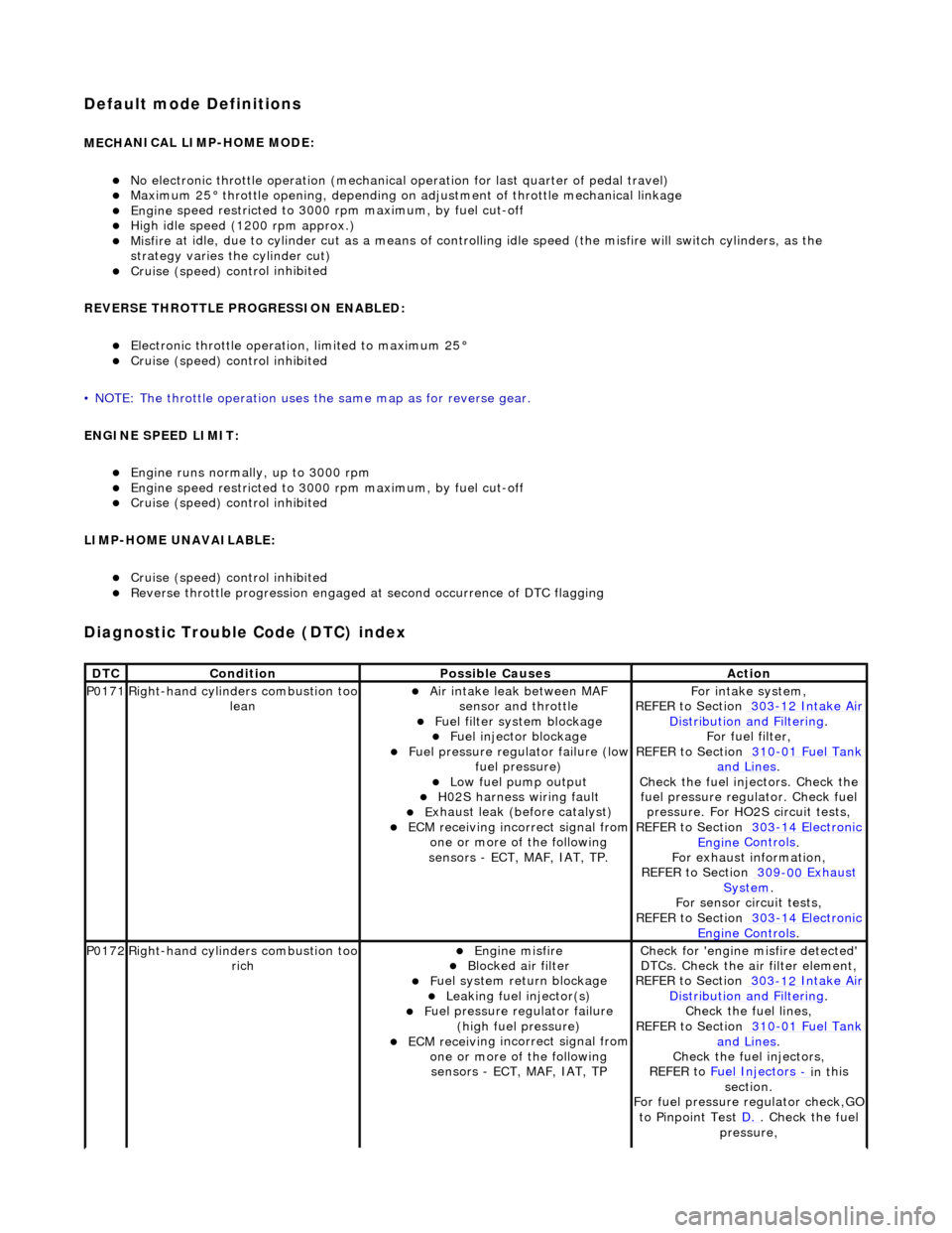
Default mode Definitions
MECH
ANICAL LIMP-HOME MODE:
No el
ectronic throttle operation (mechanical
operation for last quarter of pedal travel)
M
aximum 25° throttle opening,
depending on adjustment of th rottle mechanical linkage
Engine
speed restricted to 3000
rpm maximum, by fuel cut-off
Hi
gh idle speed (1200 rpm approx.)
Misfire
at idle, due to cylinder cut as a means of control
ling idle speed (the misfire will switch cylinders, as the
strategy varies th e cylinder cut)
Cruise (speed) contr
ol inhibited
REVERSE THROTTLE PROGRESSION ENABLED:
El
ectronic throttle operation, limited to maximum 25°
Cruise (speed) contr
ol inhibited
• NOTE: The throttle oper ation uses the same map as for reverse gear.
ENGINE SPEED LIMIT:
Engine
runs normally, up to 3000 rpm
Engine
speed restricted to 3000
rpm maximum, by fuel cut-off
Cruise (speed) contr
ol inhibited
LIMP-HOME UNAVAILABLE:
Cruise (speed) contr
ol inhibited
R
everse throttle pr
ogression engaged at second occurrence of DTC flagging
Diagnostic Trouble Code (D
TC) index
DT
C
Cond
ition
P
ossible Causes
Acti
on
P0171Right-hand cylinders combustion too
leanAir
intake leak between MAF
sensor and throttle
F
uel filter system blockage
F
uel injector blockage
F
uel pressure regulator failure (low
fuel pressure)
Low f
uel pump output
H0
2S harness wiring fault
E
xhaust leak (before catalyst)
ECM receivi
ng incorrect signal from
one or more of the following
sensors - ECT, MAF, IAT, TP.
Fo
r intake system,
REFER to Section 303
-12
Intake Air
Distribu
tion and Filtering
.
F
or fuel filter,
REFER to Section 310
-01
Fuel Tank
and Lines.
Chec
k the fuel injectors. Check the
fuel pressure regu lator. Check fuel
pressure. For HO2S circuit tests,
REFER to Section 303
-14
Electronic
Engine
Controls
.
F
or exhaust information,
REFER to Section 309
-00
Exhaust
Sy
stem
.
For se
nsor circuit tests,
REFER to Section 303
-14
Electronic
Engine
Controls
.
P0172Right-hand cylinders combustion too
ri
ch
Engine
misfire
Bl
ocked air filter
F
uel system return blockage
Leak
ing fuel injector(s)
F
uel pressure regulator failure
(high fuel pressure)
ECM receivi
ng incorrect signal from
one or more of the following sensors - ECT, MAF, IAT, TP
Chec
k for 'engine misfire detected'
DTCs. Check the air filter element,
REFER to Section 303
-12
Intake Air
Distribu
tion and Filtering
.
Chec
k the fuel lines,
REFER to Section 310
-01
Fuel Tank
and Lines.
Chec
k the fuel injectors,
REFER to Fuel Injectors
- in t
his
section.
For fuel pressure regulator check,GO
to Pinpoint Test D.
.
Check the fuel
pressure,