1998 JAGUAR X308 exhaust
[x] Cancel search: exhaustPage 1200 of 2490
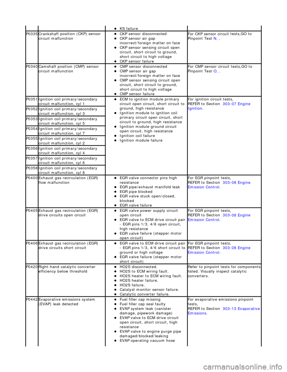
KS fail
ure
P0335Cranksh
a
ft positi
on (CKP) sensor
circuit malfunction
CK P
sensor disconnected
CKP sensor air gap
i
n
correct/foreign matter on face
CKP sensor sen
s
ing circuit open
circuit, short circuit to ground,
short circuit to high voltage
CKP s e
nsor failure
F
or CKP sensor circ ui
t tests,GO to
Pinpoint Test N.
.
P0340Camshaft position
(CMP) sensor
circuit malfunction
CM P
sensor disconnected
CMP sensor air gap
i
n
correct/foreign matter on face
CMP sensor sen
s
ing circuit open
circuit, short circuit to ground,
short circuit to high voltage
CMP s e
nsor failure
F
or CMP sensor circ ui
t tests,GO to
Pinpoint Test O.
.
P0351Igniti
on coil primary/secondary
circuit malfunction, cyl 1
ECM to ignit
ion module primary
circuit open circuit, short circuit to
ground, high resistance
Igniti
on module to ignition coil
primary circuit open circuit, short
circuit to ground, high resistance
Ignition modu le
ground circuit
open circuit, hi gh resistance
Ignition coil fail
ure
Ignition modul
e
failure
F
o
r ignition circuit tests,
REFER to Section 303
-07 En
gine
Ignition. P0352Ignit
i
on coil primary/secondary
circuit malfunction, cyl 3
P0353Ignit i
on coil primary/secondary
circuit malfunction, cyl 5
P0354Ignit i
on coil primary/secondary
circuit malfunction, cyl 7
P0355Ignit i
on coil primary/secondary
circuit malfunction, cyl 2
P0356Ignit i
on coil primary/secondary
circuit malfunction, cyl 4
P0357Ignit i
on coil primary/secondary
circuit malfunction, cyl 6
P0358Ignit i
on coil primary/secondary
circuit malfunction, cyl 8
P0400Exhaus t gas
recirculation (EGR)
flow malfunction
EGR valve c
onnector pins high
resistance
EGR pipe/exhaust manifol
d leak
EGR pipe blocke
d
EGR valve st
uck open/closed,
blocked
EGR valve fai
lure
For EGR
pinpoint t
ests,
REFER to Section 303
-08 En
gine
Emission Control.
P0405Exhaus
t gas
recirculation (EGR)
drive circuits open circuit
EGR valve power supply circuit
o p
en circuit
EGR valve t
o
ECM drive circuit pair
- EGR pins 1/3, 4/6 open circuit,
high resistance
EGR val v
e failure (stepper motor
open circuit)
For EGR pinpoint t
ests,
REFER to Section 303
-08 En
gine
Emissi
on Control.
P0406Exhaus t gas
recirculation (EGR)
drive circuits short circuit
EGR valve t o
ECM drive circuit pair
- EGR pins 1/3, 4/6 short circuit to
ground or high voltage
EGR val v
e failure (stepper motor
short circuit)
For EGR pinpoint t
ests,
REFER to Section 303
-08 En
gine
Emissi
on Control.
P0420Right-
hand catalytic converter
efficiency below threshold
HO2S di
sconnected.
HO2
S
to ECM wiring fault.
HO2
S
heater to ECM wiring fault.
HO2
S
heater failure.
HO2
S
failure.
Cat
a
lyst monitor sensor failure.
Catal
y
tic converter failure.
R
e
fer to pinpoint tests for components
listed. Visually inspect catalytic
converters.
P0442Evaporati v
e emissions system
(EVAP) leak detected
Fue l
filler cap missing
Fu
el filler cap seal faulty
EVAP system
leak (can
ister
damage, pipework damage)
EVAP v a
lve to ECM drive circuit
open circuit, short circuit, high
resistance
EVAP valve to engine pu rge pipe
damaged/blocked/leaking
EVAP ope r
ating vacuum hose
F
or evaporati
ve emissions pinpoint
tests,
REFER to Section 303
-1 3
Evaporative
Emissi
ons
.
Page 1210 of 2490
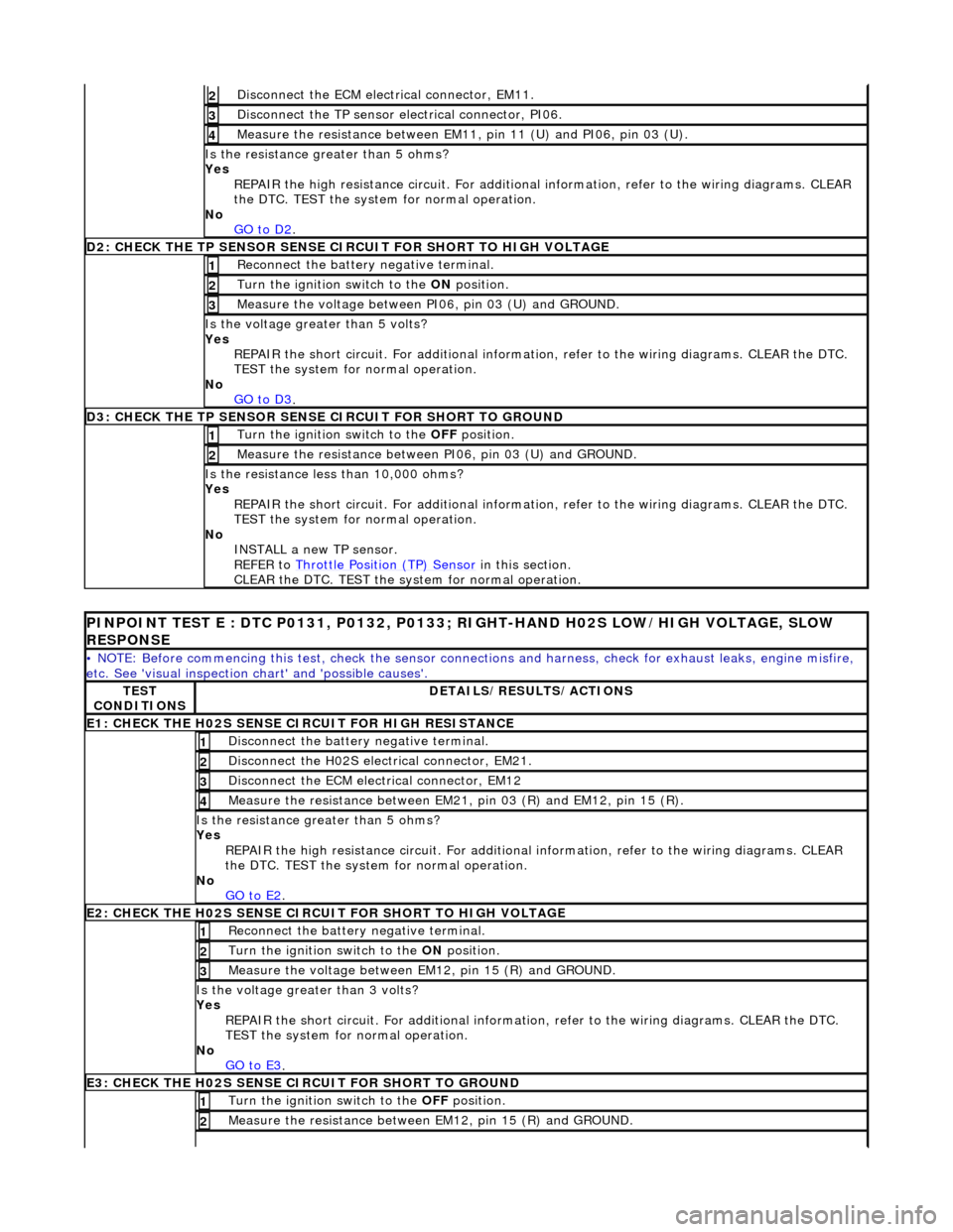
Di
sconnect the ECM electrical connector, EM11.
2
Disc
onne
ct the TP sensor electrical connector, PI06.
3
Meas
ure t
he resistance between EM11, pin 11 (U) and PI06, pin 03 (U).
4
Is th
e res
istance greater than 5 ohms?
Yes REPAIR the high resistance circui t. For additional information, refer to the wiring diagrams. CLEAR
the DTC. TEST the system for normal operation.
No GO to D2
.
D2
: CHECK THE TP SENSOR SENSE CIRCUIT FOR SHORT TO HIGH VOLTAGE
Re
connect the battery negative terminal.
1
Turn the ignition swit
ch to the ON
position.
2
Me
asure the voltage between PI06, pin 03 (U) and GROUND.
3
Is the volt
age greater than 5 volts?
Yes REPAIR the short circuit. For addi tional information, refer to the wiring diagrams. CLEAR the DTC.
TEST the system for normal operation.
No GO to D3
.
D3: CH
ECK THE TP SENSOR SENSE CIRCUIT FOR SHORT TO GROUND
Turn the ignition swi
t
ch to the OFF
position.
1
Measure t
he resistance between PI06, pin 03 (U) and GROUND.
2
Is
t
he resistance less than 10,000 ohms?
Yes REPAIR the short circuit. For addi tional information, refer to the wiring diagrams. CLEAR the DTC.
TEST the system for normal operation.
No INSTALL a new TP sensor.
REFER to Throttle Position (TP) Sensor
in this
section.
CLEAR the DTC. TEST the syst em for normal operation.
PI
NPOINT TEST E : DTC P0131, P0132, P0133; RIGHT-HAND H02S LOW/HIGH VOLTAGE, SLOW
RESPONSE
•
NOTE: Before commencing this test, check the sensor connect
ions and harness, check for exhaust leaks, engine misfire,
etc. See 'visual inspection ch art' and 'possible causes'.
TES
T
CONDITIONS
D E
TAILS/RESULTS/ACTIONS
E1
: CHECK THE H02S
SENSE CI
RCUIT FOR HIGH RESISTANCE
Disc
onnect the battery negative terminal.
1
D
is
connect the H02S electrical connector, EM21.
2
Disc
onne
ct the ECM electrical connector, EM12
3
Meas
ure t
he resistance between EM21, pin 03 (R) and EM12, pin 15 (R).
4
Is th
e res
istance greater than 5 ohms?
Yes REPAIR the high resistance circui t. For additional information, refer to the wiring diagrams. CLEAR
the DTC. TEST the system for normal operation.
No GO to E2
.
E2: CHECK THE H02S
SENSE CIRCUI
T FOR SHORT TO HIGH VOLTAGE
Re
connect the battery negative terminal.
1
Turn the ignition swi
t
ch to the ON
position.
2
Measure t
he voltage between EM12, pin 15 (R) and GROUND.
3
Is th
e volt
age greater than 3 volts?
Yes REPAIR the short circuit. For addi tional information, refer to the wiring diagrams. CLEAR the DTC.
TEST the system for normal operation.
No GO to E3
.
E3: CHECK THE H02S
SENSE CI
RCUIT FOR SHORT TO GROUND
Turn the ignition swi t
ch to the OFF
position.
1
Measure t
he resistance between EM12, pin 15 (R) and GROUND.
2
Page 1212 of 2490
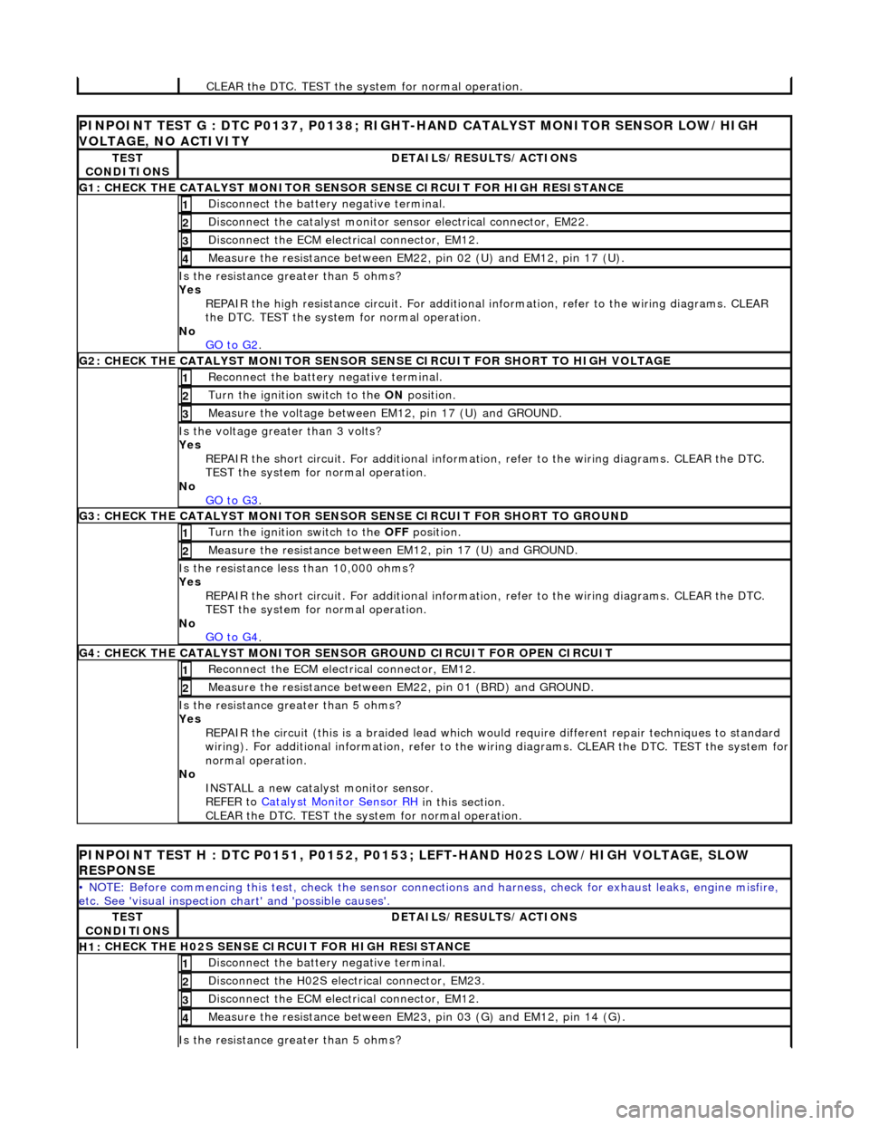
CLEAR th
e DTC. TEST the syst
em for normal operation.
PINPOINT TES
T G : DTC P0137, P0138; RIGH
T-HAND CATALYST MONITOR SENSOR LOW/HIGH
VOLTAGE, NO ACTIVITY
TE S
T
CONDITIONS
D E
TAILS/RESULTS/ACTIONS
G1
: C
HECK THE CATALYST MONITOR SENSOR SENSE CIRCUIT FOR HIGH RESISTANCE
Di
sc
onnect the battery negative terminal.
1
Di
sc
onnect the catalyst monitor sensor electrical connector, EM22.
2
Disc
onne
ct the ECM electrical connector, EM12.
3
Meas
ure t
he resistance between EM22, pin 02 (U) and EM12, pin 17 (U).
4
Is th
e res
istance greater than 5 ohms?
Yes REPAIR the high resistance circui t. For additional information, refer to the wiring diagrams. CLEAR
the DTC. TEST the system for normal operation.
No GO to G2
.
G2: CHECK
THE CATALYST MONITOR SENSOR SE
NSE CIRCUIT FOR SHORT TO HIGH VOLTAGE
Re
connect the battery negative terminal.
1
Turn the ignition swi
t
ch to the ON
position.
2
Measure t
he voltage between EM12, pin 17 (U) and GROUND.
3
Is th
e volt
age greater than 3 volts?
Yes REPAIR the short circuit. For addi tional information, refer to the wiring diagrams. CLEAR the DTC.
TEST the system for normal operation.
No
GO to G3
.
G3: CHECK
THE CATALYST MONITOR SENSOR
SENSE CIRCUIT FOR SHORT TO GROUND
Turn the ignition swit
ch to the OFF
position.
1
Measure t
he resistance between EM12, pin 17 (U) and GROUND.
2
Is t
he resistance less than 10,000 ohms?
Yes REPAIR the short circuit. For addi tional information, refer to the wiring diagrams. CLEAR the DTC.
TEST the system for normal operation.
No GO to G4
.
G4: CHECK
THE CATALYST MONITOR SENSOR
GROUND CIRCUIT FOR OPEN CIRCUIT
Reconn
ect the ECM electrical connector, EM12.
1
Meas
ure t
he resistance between EM22, pin 01 (BRD) and GROUND.
2
Is th
e res
istance greater than 5 ohms?
Yes REPAIR the circuit (this is a braide d lead which would require different repair techniques to standard
wiring). For additional information, refer to the wiring diagrams. CL EAR the DTC. TEST the system for
normal operation.
No INSTALL a new catalyst monitor sensor.
REFER to Catalyst Monitor Sensor RH
in this
section.
CLEAR the DTC. TEST the syst em for normal operation.
PINPOINT TES
T H : DTC P0151, P0152, P0153;
LEFT-HAND H02S LOW/HIGH VOLTAGE, SLOW
RESPONSE
•
NOTE: Before commencing this test, check the sensor connect
ions and harness, check for exhaust leaks, engine misfire,
etc. See 'visual inspection ch art' and 'possible causes'.
TES
T
CONDITIONS
D E
TAILS/RESULTS/ACTIONS
H1:
C
HECK THE H02S SENSE CIRCUIT FOR HIGH RESISTANCE
Di
sc
onnect the battery negative terminal.
1
D
is
connect the H02S electrical connector, EM23.
2
Disc
onne
ct the ECM electrical connector, EM12.
3
Meas
ure t
he resistance between EM23, pin 03 (G) and EM12, pin 14 (G).
4
Is th
e res
istance greater than 5 ohms?
Page 1237 of 2490
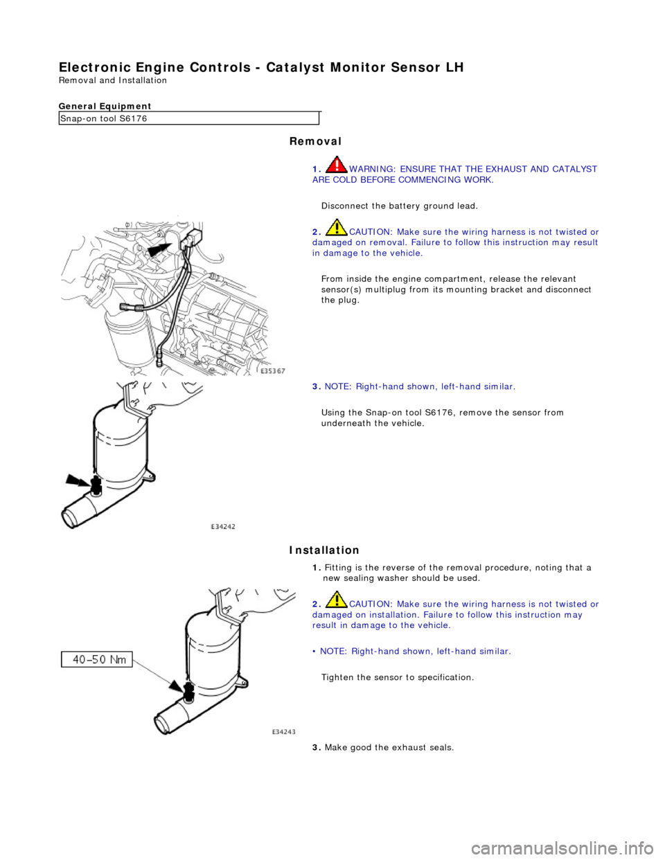
E
lectronic Engine Controls -
Catalyst Monitor Sensor LH
Re
moval and Installation
General Equipment
Remov
al
Installation
Snap
-on tool S6176
1. WARNING: ENSURE THAT THE EXHAUST AND CATALYST
ARE COLD BEFORE COMMENCING WORK.
Disconnect the battery ground lead.
2. CAUTI
ON: Make sure the wiring harness is not twisted or
damaged on removal. Failure to fo llow this instruction may result
in damage to the vehicle.
From inside the engine compartment, release the relevant
sensor(s) multiplug from its mounting bracket and disconnect
the plug.
3. NOTE
: Right-hand shown, left-hand similar.
Using the Snap-on tool S6176, remove the sensor from
underneath the vehicle.
1. Fitting is the reverse of the removal procedure, noting that a
new sealing washer should be used.
2. CAUTI
ON: Make sure the wiring harness is not twisted or
damaged on installation. Failure to follow this instruction may
result in damage to the vehicle.
• NOTE: Right-hand shown, left-hand similar.
Tighten the sensor to specification.
3. Make good th
e exhaust seals.
Page 1238 of 2490
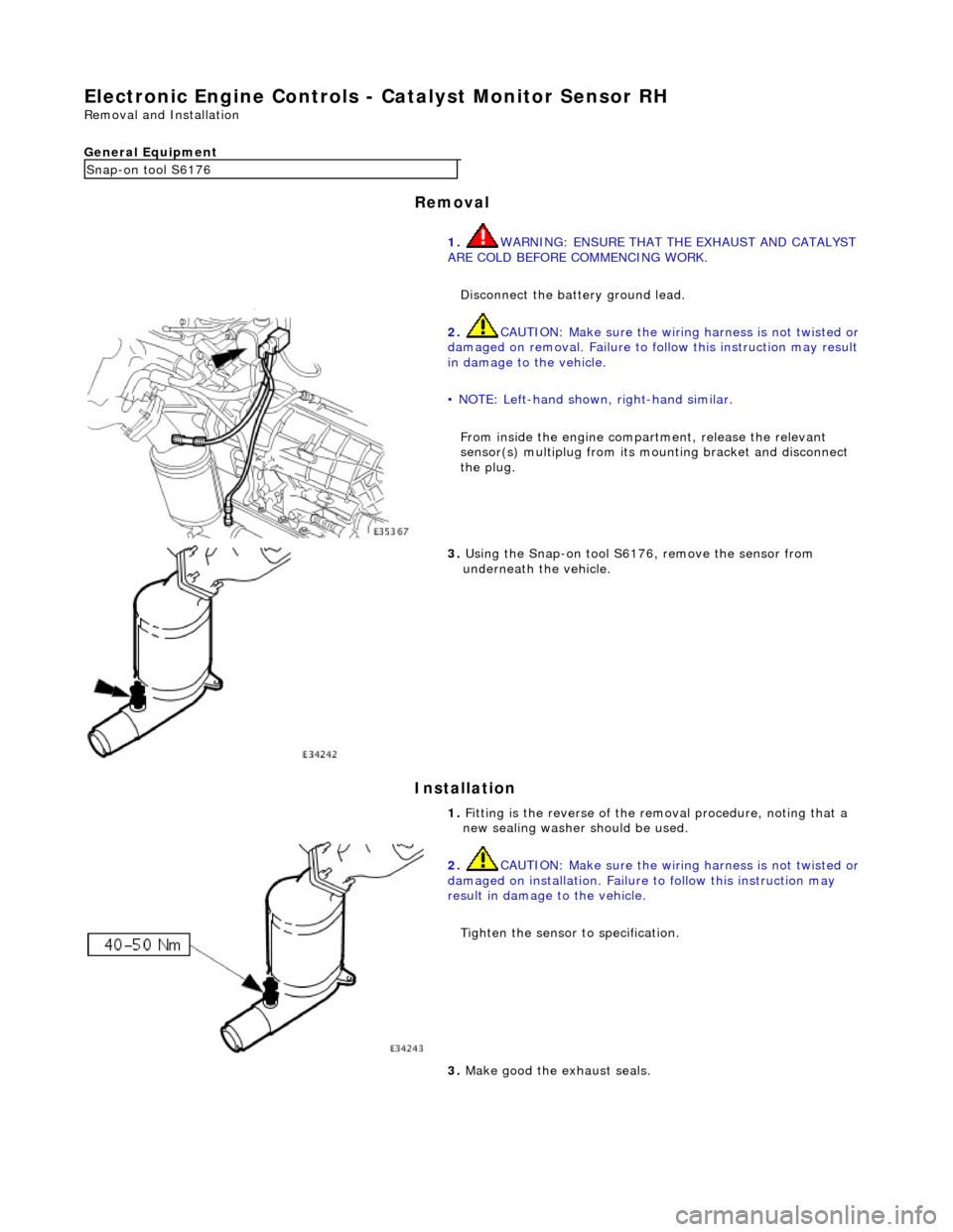
El
ectronic Engine Controls -
Catalyst Monitor Sensor RH
Remo
val and Installation
General Equipment
Remov a
l
Installation
Snap -
on tool S6176
1. WARNING: ENSURE THAT THE EXHAUST AND CATALYST
ARE COLD BEFORE COMMENCING WORK.
Disconnect the battery ground lead.
2. CAUTIO
N: Make sure the wiring harness is not twisted or
damaged on removal. Failure to fo llow this instruction may result
in damage to the vehicle.
• NOTE: Left-hand shown, right-hand similar.
From inside the engine compartment, release the relevant
sensor(s) multiplug from its mounting bracket and disconnect
the plug.
3. Us
ing the Snap-on tool S6176, remove the sensor from
underneath the vehicle.
1. Fitting is the reverse of the removal procedure, noting that a
new sealing washer should be used.
2. CAUTI
O
N: Make sure the wiring harness is not twisted or
damaged on installation. Failure to follow this instruction may
result in damage to the vehicle.
Tighten the sensor to specification.
3. Make good th e exh
aust seals.
Page 1249 of 2490
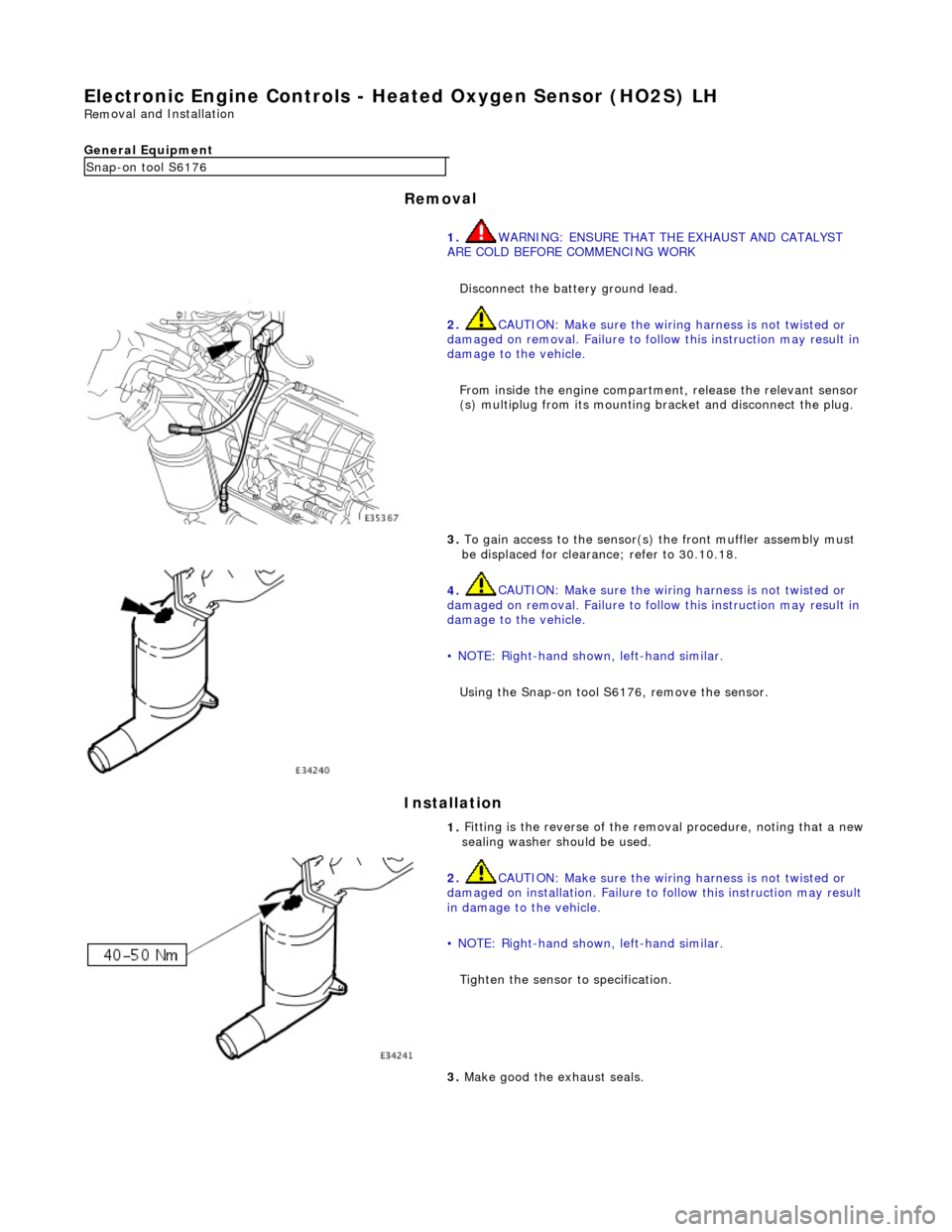
Electron
ic Engine Controls -
Heated Oxygen Sensor (HO2S) LH
Rem
oval and Installation
General Equipment
Remov
al
Installation
Snap
-on tool S6176
1. WARNING: ENSURE THAT TH E EXHAUST AND CATALYST
ARE COLD BEFORE COMMENCING WORK
Disconnect the battery ground lead.
2.
CAUTION: Make sure the wiring harness is not twisted or
damaged on removal. Failure to follow this instruction may result in
damage to the vehicle.
From inside the engine compartm ent, release the relevant sensor
(s) multiplug from its mounting bracket and disconnect the plug.
3.
To gain access to the sensor(s) the front muffler assembly must
be displaced for clearance; refer to 30.10.18.
4.
CAUTION: Make sure the wiring harness is not twisted or
damaged on removal. Failure to follow this instruction may result in
damage to the vehicle.
• NOTE: Right-hand shown, left-hand similar.
Using the Snap-on tool S6176, remove the sensor.
1.
Fitting is the reverse of the remo val procedure, noting that a new
sealing washer should be used.
2.
CAUTION: Make sure the wiring harness is not twisted or
damaged on installation. Failure to follow this instruction may result
in damage to the vehicle.
• NOTE: Right-hand shown, left-hand similar.
Tighten the sensor to specification.
3.
Make good the exhaust seals.
Page 1250 of 2490
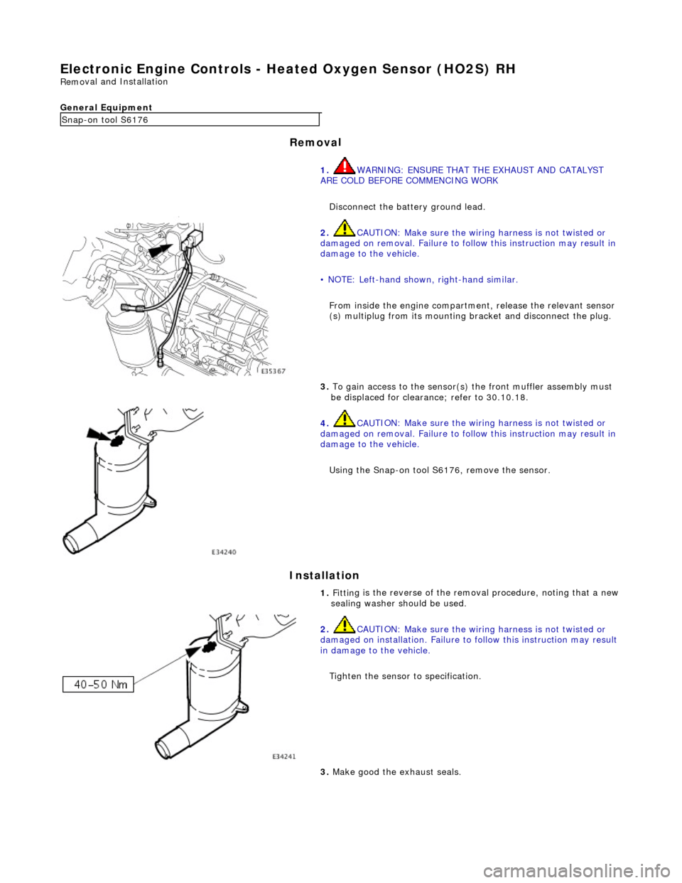
Electronic
Engine Controls -
Heated Oxygen Sensor (HO2S) RH
Remo
val and Installation
General Equipment
Remov a
l
Installation
Snap -on to
ol S6176
1. WARNING: ENSURE THAT TH E EXHAUST AND CATALYST
ARE COLD BEFORE COMMENCING WORK
Disconnect the battery ground lead.
2. CAU
TION: Make sure the wiring harness is not twisted or
damaged on removal. Failure to follow this instruction may result in
damage to the vehicle.
• NOTE: Left-hand shown, right-hand similar.
From inside the engine compartm ent, release the relevant sensor
(s) multiplug from its mounting bracket and disconnect the plug.
3. To
gain access to the sensor(s)
the front muffler assembly must
be displaced for clearance; refer to 30.10.18.
4. CAU
TION: Make sure the wiring harness is not twisted or
damaged on removal. Failure to follow this instruction may result in
damage to the vehicle.
Using the Snap-on tool S6176, remove the sensor.
1. Fittin
g is the reverse of the remo
val procedure, noting that a new
sealing washer should be used.
2. CAU
TION: Make sure the wiring harness is not twisted or
damaged on installation. Failure to follow this instruction may result
in damage to the vehicle.
Tighten the sensor to specification.
3. M
ake good the exhaust seals.
Page 1522 of 2490

Exhaust System -
Torques
ComponentNm
Nut - Downpipe catalytic converter to exhaust manifold14 - 18
Bolt - Downpipe catalytic converter to lower mounting bracket39 - 51
Bolt - Front muffler mounting to gearbox (SC)22 - 28
Bolt - Front muffler mounting to front muffler cross brace (SC)22 - 28
Bolt - Over-axle mounting to rear suspension A-frame22 - 28
Torca clamps52 - 68
Oxygen sensor to downpipe40 - 50