Page 1523 of 2490
Exhaust System - Exhaust System
Description and Operation
Exhaust Components - Normally Aspirated Vehicles
Exhaust Components - Supercharged Vehicles
Page 1524 of 2490
All vehicles are fitted with a stainless steel exhaust system which features:
Low back-pressure gas flow. Catalytic converters for mark ets having unleaded fuel. Front muffler common to the left-hand and right-hand engine cylinder banks.
Downpipe Catalytic Converter Assembly
Page 1525 of 2490
The left-hand and right-hand do wnpipe assemblies feature:
Catalytic converter with palladium / rhodium coated elem ents. The elements are uncoated for markets with only
leaded fuel.
Retained to the exhaust manifold flange by four thread ed studs. Joint-to-joint sealing is with a gasket. Engine-mounted bracket providing downpipe mounting by two nuts to the torque converter housing and two bolts to
the downpipe.
Front Muffler Assembly
ItemPart NumberDescription
1—Downpipe catalytic converter
2—Upstream heated oxygen sensor
3—Downstream oxygen sensor (North American markets only)
4—Engine mounting bracket (LHS and RHS)
Page 1530 of 2490
The upstream heated oxygen sensor is located at the catalytic converter inlet and detects the concentration of oxygen in the
raw exhaust gases; an internal heater reduces the warm up time of the sensor output.
An oxygen sensor (without heater) is located at the converter outlet.
The ECM receives input signals from the se nsors and varies the fuel injector duration (mixture) to provide optimum gas
emissions.
Circuit Diagram, O2 Sensors / ECM
Page 1533 of 2490

Exhaust System - Exhaust System
Diagnosis and Testing
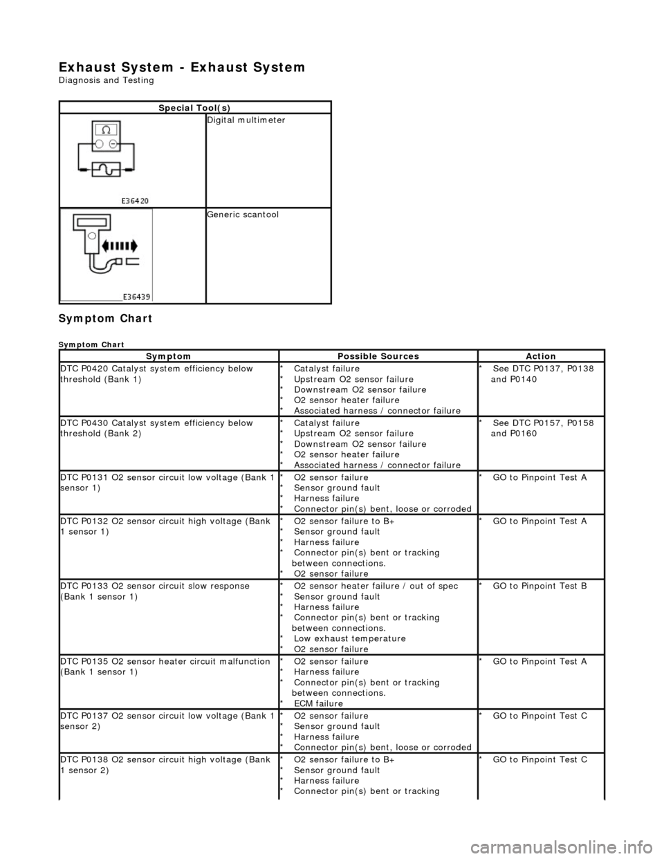
Symptom Chart
Symptom Chart
Special Tool(s)
Digital multimeter
Generic scantool
SymptomPossible SourcesAction
DTC P0420 Catalyst system efficiency below
threshold (Bank 1)Catalyst failure
Upstream O2 sensor failure
Downstream O2 sensor failure
O2 sensor heater failure
Associated harness / connector failure
*
*
*
*
*See DTC P0137, P0138
and P0140
*
DTC P0430 Catalyst system efficiency below
threshold (Bank 2)Catalyst failure
Upstream O2 sensor failure
Downstream O2 sensor failure
O2 sensor heater failure
Associated harness / connector failure
*
*
*
*
*See DTC P0157, P0158
and P0160
*
DTC P0131 O2 sensor circuit low voltage (Bank 1
sensor 1)O2 sensor failure
Sensor ground fault
Harness failure
Connector pin(s) bent, loose or corroded
*
*
*
*GO to Pinpoint Test A
*
DTC P0132 O2 sensor circuit high voltage (Bank
1 sensor 1)O2 sensor failure to B+
Sensor ground fault
Harness failure
Connector pin(s) bent or tracking
between connections. O2 sensor failure
*
*
*
*
*GO to Pinpoint Test A
*
DTC P0133 O2 sensor circuit slow response
(Bank 1 sensor 1)O2 sensor heater failure / out of spec
Sensor ground fault
Harness failure
Connector pin(s) bent or tracking
between connections. Low exhaust temperature
O2 sensor failure
*
*
*
*
*
*GO to Pinpoint Test B
*
DTC P0135 O2 sensor heater circuit malfunction
(Bank 1 sensor 1)O2 sensor failure
Harness failure
Connector pin(s) bent or tracking
between connections. ECM failure
*
*
*
*GO to Pinpoint Test A
*
DTC P0137 O2 sensor circuit low voltage (Bank 1
sensor 2)O2 sensor failure
Sensor ground fault
Harness failure
Connector pin(s) bent, loose or corroded
*
*
*
*GO to Pinpoint Test C
*
DTC P0138 O2 sensor circuit high voltage (Bank
1 sensor 2)O2 sensor failure to B+
Sensor ground fault
Harness failure
Connector pin(s) bent or tracking
*
*
*
*GO to Pinpoint Test C
*
Page 1534 of 2490

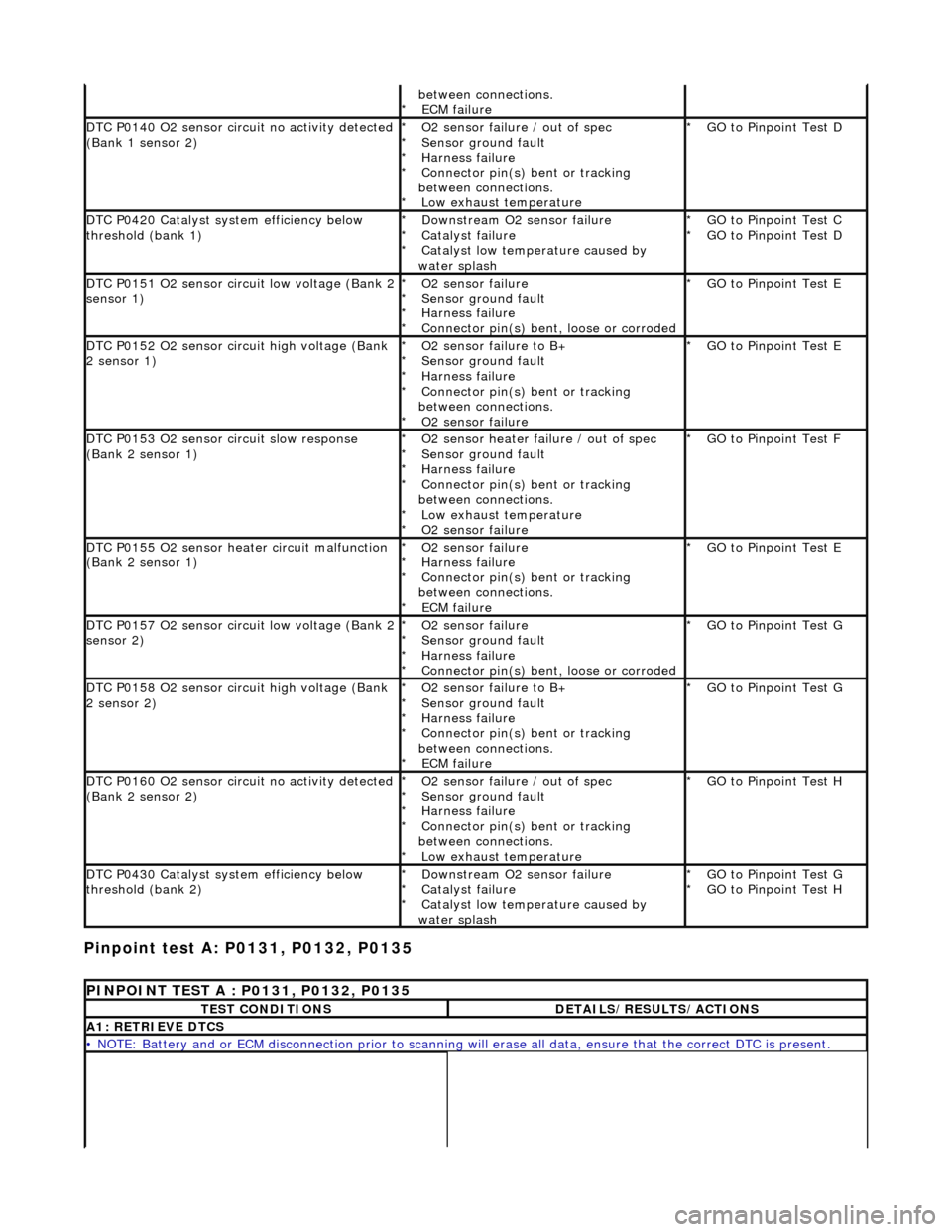
Pinpoint test A: P0131, P0132, P0135
between connections. ECM failure
*
DTC P0140 O2 sensor circuit no activity detected
(Bank 1 sensor 2)O2 sensor failure / out of spec
Sensor ground fault
Harness failure
Connector pin(s) bent or tracking
between connections. Low exhaust temperature
*
*
*
*
*GO to Pinpoint Test D
*
DTC P0420 Catalyst system efficiency below
threshold (bank 1)Downstream O2 sensor failure
Catalyst failure
Catalyst low temperature caused by
water splash
*
*
*GO to Pinpoint Test C
GO to Pinpoint Test D
*
*
DTC P0151 O2 sensor circuit low voltage (Bank 2
sensor 1)O2 sensor failure
Sensor ground fault
Harness failure
Connector pin(s) bent, loose or corroded
*
*
*
*GO to Pinpoint Test E
*
DTC P0152 O2 sensor circuit high voltage (Bank
2 sensor 1)O2 sensor failure to B+
Sensor ground fault
Harness failure
Connector pin(s) bent or tracking
between connections. O2 sensor failure
*
*
*
*
*GO to Pinpoint Test E
*
DTC P0153 O2 sensor circuit slow response
(Bank 2 sensor 1)O2 sensor heater failure / out of spec
Sensor ground fault
Harness failure
Connector pin(s) bent or tracking
between connections. Low exhaust temperature
O2 sensor failure
*
*
*
*
*
*GO to Pinpoint Test F
*
DTC P0155 O2 sensor heater circuit malfunction
(Bank 2 sensor 1)O2 sensor failure
Harness failure
Connector pin(s) bent or tracking
between connections. ECM failure
*
*
*
*GO to Pinpoint Test E
*
DTC P0157 O2 sensor circuit low voltage (Bank 2
sensor 2)O2 sensor failure
Sensor ground fault
Harness failure
Connector pin(s) bent, loose or corroded
*
*
*
*GO to Pinpoint Test G
*
DTC P0158 O2 sensor circuit high voltage (Bank
2 sensor 2)O2 sensor failure to B+
Sensor ground fault
Harness failure
Connector pin(s) bent or tracking
between connections. ECM failure
*
*
*
*
*GO to Pinpoint Test G
*
DTC P0160 O2 sensor circuit no activity detected
(Bank 2 sensor 2)O2 sensor failure / out of spec
Sensor ground fault
Harness failure
Connector pin(s) bent or tracking
between connections. Low exhaust temperature
*
*
*
*
*GO to Pinpoint Test H
*
DTC P0430 Catalyst system efficiency below
threshold (bank 2)Downstream O2 sensor failure
Catalyst failure
Catalyst low temperature caused by
water splash
*
*
*GO to Pinpoint Test G
GO to Pinpoint Test H
*
*
PINPOINT TEST A : P0131, P0132, P0135
TEST CONDITIONSDETAILS/RESULTS/ACTIONS
A1: RETRIEVE DTCS
• NOTE: Battery and or ECM disconnection prior to scanning wi
ll erase all data, ensure that the correct DTC is present.
Page 1546 of 2490
Connect the scan tool 1
Have the DTC(s) and freeze frame data been recorded?
Yes GO to B2
B2: CHECK FOR LOW EX HAUST TEMPERATURE
Check the engine and exhaust system for normal running
temperature 1
Is the engine and exhaust sy stem up to normal running
temperature?
Yes GO to B3
No Rectify possible leaking exhaust manifold / catalyst, general
causes of an over rich mixture and engine cooling system
operation. Test the system for correct operation.
GO to B8
B3: CHECK FOR O2 SENS OR HEATER CONTINUITY
Ignition switch to position 0 1
Disconnect EM021
Bracket on top of gearbox or Bulkhead rear of engine
2
With EM021 disconnected, measure the resistance between
EM021/001 and EM021/002. 3
Is the resistance between 4 and 10 OHM?
Yes
GO to B4
No Renew O2 sensor, reconnect plug(s).
GO to B8
B4: CHECK FOR O2 SENSOR FAILURE
Page 1570 of 2490
Connect the scan tool 1
Have the DTC(s) and freeze frame data been recorded?
Yes GO to D2
D2: CHECK FOR LOW EXHAUST TEMPERATURE
Check the engine and exhaust system for correct operation
and normal running temperature 1
Is the engine and exhaust system operating correctly and up to
normal running temperature?
Yes GO to D3
No Rectify leaking exhaust manifold / catalyst, general causes of
an over rich mixture and engine cooling system operation
and test the system for correct operation.
GO to D7
D3: CHECK FOR O2 SENSOR FAILURE
Run the engine for a period to warm the sensor and then
maintain a steady speed of approximately 2500 rpm. 1
Measure the voltage between EM022/001 and EM022/002. 2