Page 1518 of 2490

Automatic Transmission/Transaxle External Contro ls - 4.0L SC V8 - AJ26 -
Transmission Control Switch (TCS)
Removal and Installation
Removal
Installation
1. Position the gear selector to 'N' to provide clearance for
removing the console.
2. Disconnect the vehicle battery ground lead.
3. Remove the J-gate surroun d, operation 76.25.24.
4. Remove the console finisher vene er panel, operation 76.47.26.
5. Remove the console assembly, operation 76.25.01.
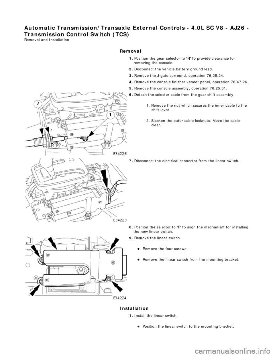
6. Detach the selector cable from the gear shift assembly.
1. Remove the nut which secures the inner cable to the shift lever.
2. Slacken the outer cable locknuts. Move the cable clear.
7. Disconnect the electrical conne ctor from the linear switch.
8. Position the selector to 'P' to align the mechanism for installing
the new linear switch.
9. Remove the linear switch.
Remove the four screws.
Remove the linear switch fro m the mounting bracket.
1. Install the linear switch.
Position the linear switch to the mounting bracket.
Page 1520 of 2490
moving the set position of either the gear selector lever or the selector lever on the transmission casing.
3. Tighten to 22-28 Nm.
4. Verify the 'N' setting.
6. Check that all released connec tors are safely insulated and
connect the vehicle battery.
7. Switch ON the ignition.
8. Adjust the position of the linear switch so that the selector 'N'
position graphic illuminates. Ti ghten the four screws to 0,7-1
Nm.
9. Move the gear selector to 'R' to confirm that the 'R' position
graphic illuminates.
10. Check that the engine will start when the gear selector is in
the 'N' and 'P' positions, bu t not in any other position.
11. Move the gear selector to 'N'.
12. Switch OFF the ignition.
13. Disconnect the battery.
14. Install the console assembly, operation 76.25.01.
15. Install the console finisher veneer panel, operation 76.47.26.
16. Install the J-gate surround, operation 76.25.24.
17. Perform the Battery Reconnection Procedure described in
Operation 86.15.15.
Page 1524 of 2490
All vehicles are fitted with a stainless steel exhaust system which features:
Low back-pressure gas flow. Catalytic converters for mark ets having unleaded fuel. Front muffler common to the left-hand and right-hand engine cylinder banks.
Downpipe Catalytic Converter Assembly
Page 1694 of 2490
P a
rts List
The fuel level sensor is mounte d on the fuel tank vertical face and reacts to level changes via a float and pivot which is
connected to a potentiometer. As the fuel level drops the resistance increases.
The fuel level sensor can be serviced without removing the tank.
It e
m
Par
t
Number
De
scr
iption
1—Lockin
g rin
g
2—Fue
l
level sensor
3—Seal
Fuel
Level Sensor
Page 1744 of 2490

Speed Control - Speed
Control
D
iagn
osis and Testing
Pri
n
ciples of operation
The s
p
eed (cruise) control sy
stem is activated by an ON/OFF master switch in the J-gate surround, which has an integral
LED to indicate status.
The steering wheel switches allow the driver to set the speed, increase or decrease the selected speed, cancel and resume
the facility without his/her hand ever leaving the steering wheel
The vehicle speed can be increased an d decreased in increments of 2 kmh (1 mph) by briefly pressing the + or - buttons up
to a maximum of five times.
Alternatively, the + or - button can be held until th e desired speed is reached.
The selected speed (by whichever method) w ill be displayed in the message center.
The system will not function at speeds below 26 kmh (16 mph), and can be cancelled from the master switch, the steering
wheel switches, and by depressing th e brake pedal. The system can be overridden by accelerating as normal.
In
spection and Verification
1.
1. Veri fy the customer concern.
2. 2. Vis
ually inspect for obvious signs of mechanical or electrical damage.
3. 3. If an obvious cause for an observed or reported concern is found, correct the cause (if possible) before proceeding
to the next step.
4. 4. If the cause is not visually evident, verify the symptom, check for DTCs and follow the routines in this section.
Vi
sual Inspection Chart
Diagnostic Trouble Code (D
TC) index
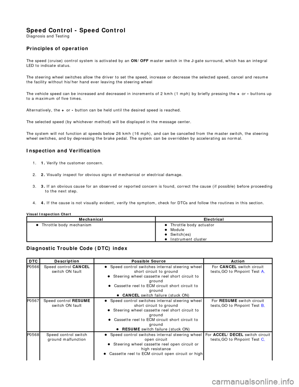
MechanicalElectrical
Throttle body mechan
ism
Throttle body actuator
Module Switch(es) Instrument cluster
DTC
De
scr
iption
Possib
l
e Source
Acti
o
n
P0566Speed
c
ontrol
CANCEL
switch ON fault
Speed
control switches internal steering wheel
short circuit to ground
St
eering wheel cassette reel short circuit to
ground
Cassette reel to ECM circ
uit short circuit to
ground
CANCEL
switch failure (stuck ON)
Fo
r
CANCEL switch circuit
tests,GO to Pinpoint Test A.
P0567Speed c
ontrol
RESUME
switch ON fault
Speed
control switches internal steering wheel
short circuit to ground
St
eering wheel cassette reel short circuit to
ground
Cassette reel to ECM circ
uit short circuit to
ground
RESUME swit
ch failure (stuck ON)
For
RESUME switch circuit
tests,GO to Pinpoint Test B.
P0568Spee
d control switch
ground malfunction
Speed
control switches internal steering wheel
open circuit
St
eering wheel cassette reel open circuit or
high resistance
Cassette reel to ECM ci
rcuit open circuit or high
For
ACCEL/DECEL switch circuit
tests,GO to Pinpoint Test C.
Page 1761 of 2490

Climate Co
ntrol System - General In
formation - Air Conditioning (A/C)
System Check - Re tail Procedure
Gen
eral Procedures
E
vacuating the Manifold Gauge Set
Connecting the Manifold Gauge Set
C
AUTION: Only use hoses with connectors wh
ich are dedicated to HFC 134A charge ports.
Stabilizing the System
1.
At
tach the center (service) hose to a vacuum pump and start
the pump. Open fully both high and low valves and allow the
vacuum to remove air and mois ture from the manifold set for
at least five minutes.
CAUTION: It is imperative th at the vacuum pump is not
subjected to a positi ve pressure of any degree. Therefore the
pump must be fitted wi th an isolation valve at the center (service
hose) connection and this valve mu st be closed before the pump
is switched off. This operation replaces the 'purge' procedure used
on previous systems. Observe the manufacturer's
recommendation with regard to vacuum pump oil changes.
Turn the vacuum pump off and isol ate it from the center service
hose but do not open the hose to atmosphere.
1. Att
achment of the hose quick release connectors to the high
and low side system ports is stra ightforward, provided that the
high and low valves are closed and the system is NOT
operational.
WARNING: UNDER NO CIRCUMSTANCES SHOULD THE
CONNECTIONS BE MADE WITH THE SYSTEM IN OPERATION OR
THE VALVES OPEN. SHOULD THE VALVES BE OPEN AND A
VACUUM PUMP OR REFRIGERANT CONTAINER ATTACHED, AN
EXPLOSION COULD OCCUR AS A RESULT OF HIGH PRESSURE
REFRIGERANT BEING FORCED BACK INTO THE VACUUM PUMP OR
CONTAINER.
Assessment of system operating efficiency and fault
classification may be achieved by using the facilities on your
Recovery / Recharging / Recycling station, follow the
manufacturer's instructions implicitly and observe all safety
considerations.
1. Accurate test gauge data wi
ll on
ly be attained if the system
temperatures and pressures are stabilized.
E
nsure that equipment and hoses cannot come into
contact with engine moving parts or sources of heat.
It is recommended th at a free standing air
mover is placed
in front of the vehicle to provide air flow through the
condenser / cooling system.
St
art the engine, allow it to attain normal working
temperature and set at fast idle (typically 1200 to 1500
rpm).
Select full
air condit
ioning performance.
With
all temperatures and pres
sures stable, or displaying
symptoms of faults; begin relevant test procedures.
Page 1798 of 2490
Air Conditioning - Air Conditioning
Description and Operation
Introduction
Parts List
The climate control system features fully automatic control of temperature, blower speed (airflow) and air distribution to
maintain optimum comfort under most driving conditions.
Manual controls are provided to allow the operator to over-ride automatic operation.
System Features
ItemPart NumberDescription
1—Fascia panel with integral ducting
2—Heater / cooler assembly
3—A/CCM
4—Blower LH and RH
5—Plenum
6—Control panel
7—Solar sensor
8—Assembly valve - water
9—Assembly pump - water
10—Temperature sensor - external
11—Compressor
12—Pressure switch - 4 level
13—Motorized in-car aspirator (LHD shown)
14—Receiver drier
15—Condenser
Page 1821 of 2490

Control Components - Control Components
Description and Operation
System Controls
The climate control system is controlled by : 1. 1. Manual input from the operator, via the center console located control panel.
2. 2. Automatically by means of the A/CCM.
Output is based upon input from the following devices:
Motorized In-car aspirator External air temperature sensor Coolant temperature sensor Heater 'air-off' (the temperature of the air leaving the matrix fins) temperature sensor Evaporator 'air-off' (the temperature of the air leaving the evaporator fins) temperature sensor Solar sensor Left hand blower recirculation / fresh air flap potentiometer Right hand blower recirculation / fresh air flap potentiometer Upper air distribution box (ADB) center and side face flap servomotor potentiometer ADB defrost flap servomotor potentiometer Air conditioning unit Foot flap servomotor potentiometer Air conditioning unit Cool Air Bypass flap servomotor potentiometer Thumbwheel controls on the facia vent assemblies which provide manu al adjustment of the airflow volume. Road and engine speed signals input to the A/CCM
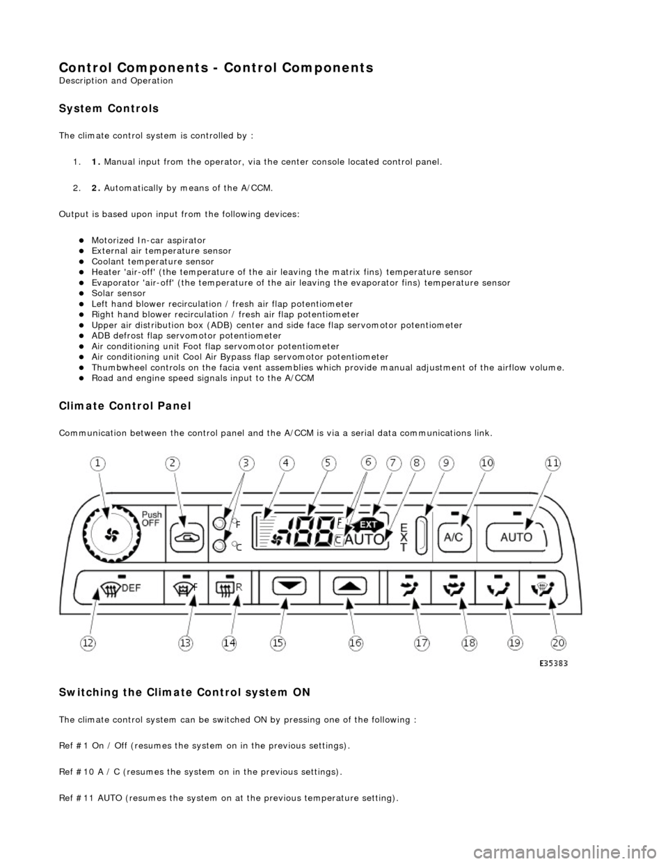
Climate Control Panel
Communication between the control panel and the A/CCM is via a serial data communications link.
Switching the Climate Control system ON
The climate control system can be switched ON by pressing one of the following :
Ref #1 On / Off (resumes the system on in the previous settings).
Ref #10 A / C (resumes the system on in the previous settings).
Ref #11 AUTO (resumes the system on at the previous temperature setting).