Page 1245 of 2490
E
lectronic Engine Controls - Engine Control Module (ECM)
Re
moval and Installation
Remov
al
Installation
1.
Disc
onnect battery ground cable (IMPORTANT, see SRO
86.15.19 for further information).
2. R
emove ECM housing cover.
3. RHD only: Remove security bracket securing screws.
R
emove bracket.
4. Disconnect electrical connectors.
5. Li
ft ECM from housing.
6. RHD only: Remove security bracket securing screws.
R
emove brackets.
1. NOTE: A replacement ECM may only be obtained from an
authorised Jaguar dealer and MU ST be ordered against the VIN.
• NOTE: Check condition of ho using seals and replace as
necessary.
Installation is a reversal of the removal procedure.
2. Synchronize ECM, KTM and BPM using PDU.
3. Complete engine set- up using JDS/PDU.
Page 1262 of 2490

Contains th
e hydraulic system pump.
Contains
th
e fluid temperature sensor.
The epicyclic geartrain:
Provi des fi
ve forward gears and Reverse.
Has
h
ydraulically actuated, multi-disk clutches, to select the required gear ratios.
Feature
s clutch-to-clutch operation to permit
gear shifts for uninterrupted power flow.
The electro-hydraulic control unit:
Is lo c
ated in the lower part of
the unit, within the fluid pan.
Is controlled
by the TCM (transmissio
n control module), and the manual selector valve which is cable operated.
Re
gulates the flow of fluid to the ge
artrain clutches via three solenoid-operated valv es and the manual selector
valve.
Has fi ve pressure
regulators for controll
ing fluid pressures within the system.
Is con
nected to the TCM via a 16-way connector mounted on
the left-hand side of the transmission casing. Refer to
Connector Pins Identification, Section 307-01A.
The hydraulic system pump:
Is l o
cated at the front of the transmission casing.
Is dri
v
en from the impeller hub,
pressurising the fluid whenever the engine is running.
Supplie
s fluid under pressure to the torq
ue converter, geartrain, electro-hydr aulic control unit and the lubrication
circuit.
D r
aws fluid from the fluid pa
n below the transmission casing, through a filter.
The rear extension housing:
Is bolt
ed to the rear of the transmission casing.
Provides the rear engine / transmi
ssion mo
unting point; refer to section 303-01.
Carrie
s the transmission output shaft oil seal.
Filled-for-l
i
fe Fluid System
The
transm
ission is 'filled for life' and
does not require fluid changes, except where extreme driving conditions prevail.
Routine level checking is not required and a dipstick is not pr ovided. A level / filler plug is fitted for level checking and
replenishment, following service actions; see 303-01 General Procedures.
Transmission Torque Converter
Page 1267 of 2490
Transmission Speed Sensors (Gear Shift Control)
Operation
There are two speed sensors within the transmission assembly; one on the input shaft or convertor turbine and the other on the output shaft.
Both sensors are of the inductive type and sense toothed wheels; the input wheel having 30 teeth and the output 36 teeth.
Temperature ( °C)Nominal Resistance (kOHM)
-20685
0812
20953
401107
601276
801458
1001653
Page 1269 of 2490

2.2. Check on non-volatile diagnostic memory by wr iting a test pattern and then reading it back.
3. 3. Internal 'watchdog' hardware to check whether the TCM has crashed.
Transmission Control Module Supply Voltage
The TCM monitors battery and igni tion switched supply voltages.
A permanent supply is used to maintain a battery backed 'memor y'. Should this supply be cut, due to battery disconnection
perhaps, the 'adaptive shift' valu es will be lost. This will result in a small reduction in shift quality for a period until th e
adaptions are 're-learned'
The TCM will adopt 'limp home' mode as a result of the supply voltage being >16V or <7V with an engine speed >1600
rpm.
Should the ignition supply be >7V but <9V the TCM will hold the gear that it has currently selected. If after 2.5 seconds,
with the engine speed >1600 rpm, the voltage remains at this level, 'limp home' mode will be adopted. The 2.5 second
delay is built in to prevent reaction to a momentary voltage fluctuation.
Operation
CAUTION: Disconnection of the TCM and / or the vehicle batt ery will cause system adaptions to be lost; this may be
apparent by shift quality degradation. Fo llowing reconnection, a period of 'varied' driving will reinstate adaptions and thus
normal operation. Please ensure that the customer is made aware that the adaption period is variable and may occur after
handover, as the transmission re-learns the prevailing driving style.
• NOTE: Should the TCM fail, please ensure that the control housing cooling fan is operating correctly. Failure of the cooling
fan MUST be rectified before renewing the TCM and details of a fan fa ilure should accompany the returned TCM.
The TCM processes information received in both analogue and digital form, such as:
Transmission input speed Transmission output speed Throttle position Pedal demand Gear selector position Engine torque Engine speed Transmission oil temperature Mode switch
This information is then used by the TC M to control shift energy management and decide which shift program to implement
and which gear to select.
The TCM uses the various sensors and inpu ts to monitor the correct operation of the system an d is programmed to take
default action and inform the operator when a fault occurs.
Safety Functions
The safety functions are designed to safeguard against inappr opriate actions by the operator as well as against system
malfunctions. The system prevents reve rse gear from being engaged at high forward speeds and prevents manual
downshifting at excessive engine speeds; these functions are not operational in mechanical limp-home mode.
The TCM constantly monitors the transmissi on for faults. In the event of a problem the TCM will adopt a 'limp home' mode
in which only P R N D - (selector in D but only fourth gear is enabled) are available. The operator will be made aware of
certain faults by an in strument panel warning.
The electrical and diagnostic system has been designed such that system integrity is protected at all times, the safety
concept being based on th e following three points:
Page 1271 of 2490

Controller Area Network (CAN)
The TCM is an integral part of the CAN system which facilitates the interchange of real-time data between control modules
and sensors. Please see section 303- 14 for a full description of CAN.
OBDII Interface
Data concerning OBDII related transmission failures is stored in the ECM for access via the J1962 socket.
System Functions
Range Selection
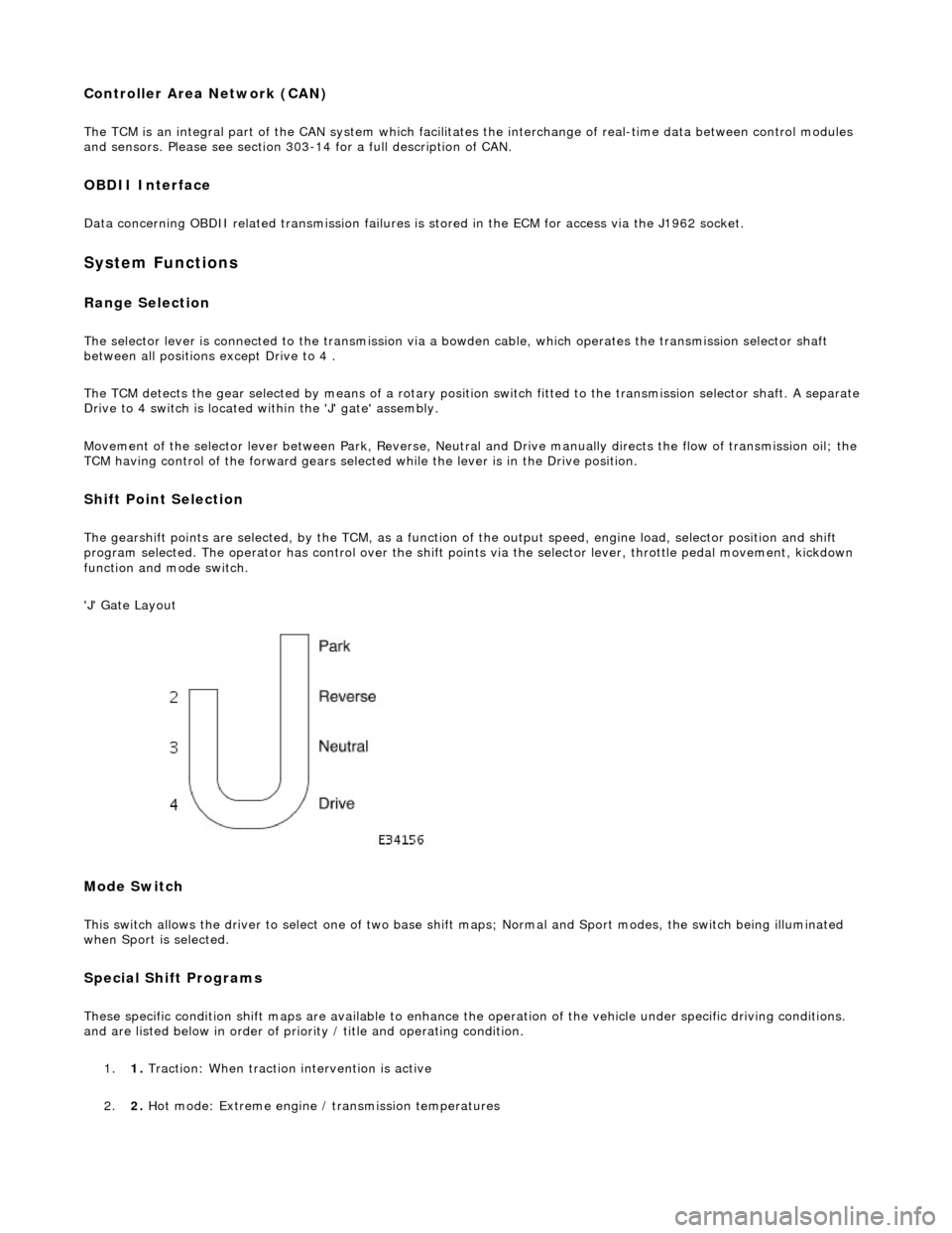
The selector lever is connected to the transmission via a bowden cable, which operates the transmission selector shaft
between all positions except Drive to 4 .
The TCM detects the gear selected by means of a rotary position switch fitted to the transmission selector shaft. A separate
Drive to 4 switch is located within the 'J' gate' assembly.
Movement of the selector lever between Park, Reverse, Neutral and Drive manually directs th e flow of transmission oil; the
TCM having control of the forward gears selected while the lever is in the Drive position.
Shift Point Selection
The gearshift points are selected, by the TCM, as a function of the output speed, engine load, selector position and shift
program selected. The operator has control over the shift points via the selector lever, throttle pedal movement, kickdown
function and mode switch.
'J' Gate Layout
Mode Switch
This switch allows the driver to select one of two base shift maps; Normal and Sport modes, the switch being illuminated
when Sport is selected.
Special Shift Programs
These specific condition shift maps are available to enhance the operation of the vehicle under specific driving conditions.
and are listed below in order of priority / title and operating condition.
1. 1. Traction: When traction intervention is active
2. 2. Hot mode: Extreme engine / transmission temperatures
Page 1272 of 2490

3.3. Gradient: Under specific speeds and loads
4. 4. Cruise: During cruise control
5. 5. Manual: Shift map when the LH side of the 'J gate' is used
Three specific condition shift maps have a higher priority than the two base shift maps and will intervene when appropriate
conditions prevail for traction, gradient or cruise.
When traction control (engine or brake system derived) is operational the TCM will implement the traction map to maximise
control of wheel slip.
The gradient maps are intended to enhance vehicle drivability when towing or climbing a gradient. The TCM will implement
the maps when increased driving resistan ce is detected and enhanced drivability, cooling and increa sed performance is
appropriate.
The cruise map is intended to minimize unwanted gearshifts and 'hunting' and is activated when cruising near to the set
speed, or resuming.
Connector Pins Identification
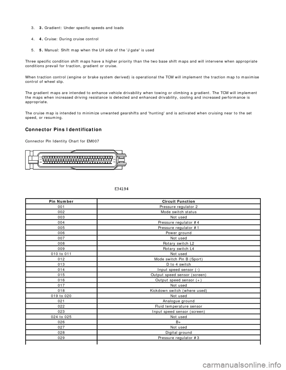
Connector Pin Identity Chart for EM007
Pin NumberCircuit Function
001Pressure regulator 2
002Mode switch status
003Not used
004Pressure regulator #4
005Pressure regulator #1
006Power ground
007Not used
008Rotary switch L2
009Rotary switch L4
010 to 011Not used
012Mode switch Pin B (Sport)
013D to 4 switch
014Input speed sensor (-)
015Output speed sensor (screen)
016Output speed sensor (+)
017Not used
018Kickdown switch (where used)
019 to 020Not used
021Analogue ground
022Fluid temperature sensor
023Input speed sensor (screen)
024 to 025Not used
026B+
027Not used
028Digital ground
029Pressure regulator #3
Page 1358 of 2490
Installation
1.
NOTE: A replacement TCM may only be obtained from an
authorized Jaguar dealer and MU ST be ordered against the VIN.
Fitting a new TCM is the revers e of the removal procedure.
At this point ensure that the ECM is correctly located and
pushed fully rearward against the housing.
2. Connect the battery and fit the battery cover..
Reset the radio and the clock.
Page 1384 of 2490
5. Fit the transmission to the engine.
Loosely assemble - Cooler pipe clip.
Loosely assemble - Ground lead.
Loosely assemble - Ca talyst brackets.
1. Tighten in sequence 1, 2, 3, 4 as shown on the illustration, then the others in any order.
6. Reposition the mounting brac ket for the engine harness
connector and fit the securing bolts.
7. Connect the drive shaft, aligning any marks made when
removing - if applicable. Tighten the bolts to the specified
torque figure.
8. Fit the engine rear mounting and tighten the centre bolt and
outer bolts to the specified torque figures.
Check that the hooks of the engine support beam are not
trapped, before tighteni ng the rear mounting.
Check that the safety chain on the transmission jack will