Page 2113 of 2490
Rear View Mirrors - Auto-Dimming Interior Mirror
Removal and Installation
Removal
Installation
1.
Remove roof console for access and disconnect interior mirror
harness multiplugs. Refer to 76.13.69.90.
2. Remove upper cover from mirror stem.
3. Remove rain sensor unit. Refer to Section 501.16.
4. CAUTION: When removing mirror from base, care must
be exercised to ensure that base is not detached from windshield.
Applying firm downward pre ssure, remove mirror assembly
from base.
1. Position mirror at bottom of base and apply firm upward
pressure to fully seat and secure in position.
2. Install upper cover to mirror stem.
3. Position roof console at head er and connect mirror harness
multiplugs.
4. Install rain sensor unit. Refer to Section 501.16.
5. Install roof console. Refer to 76.13.69.
Page 2118 of 2490
Rear View Mirrors - Interior Mirror
Removal and Installation
Removal
CAUTION: When removing mirror from base, care must be exercised to ensure that base is not detached from
windshield.
Installation
1. Remove upper cover from mirror stem.
2. Remove rain sensor unit. Refer to Section 501.16.
3. Applying firm downward pre ssure, remove mirror assembly
from base.
1. Position mirror at bottom of base and apply firm upward
pressure to fully seat and secure in position.
2. Install rain sensor unit. Refer to Section 501.16.
3. Install upper cover to mirror stem.
Page 2140 of 2490
Seating - Front Seat Head Restraint
Removal and Installation
Removal
Installation
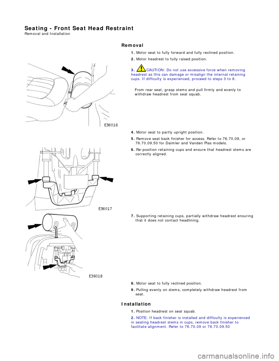
1. Motor seat to fully forward and fully reclined position.
2. Motor headrest to fully raised position.
3. CAUTION: Do not use excessive force when removing
headrest as this can damage or misalign the internal retaining
cups. If difficulty is experienced, proceed to steps 3 to 8.
From rear seat, gras p stems and pull firm ly and evenly to
withdraw headrest from seat squab.
4. Motor seat to partly upright position.
5. Remove seat back finisher for access. Refer to 76.70.09, or
76.70.09.50 for Daimler and Vanden Plas models.
6. Re-position retaining cups and en sure that headrest stems are
correctly aligned.
7. Supporting retaining cu ps, partially withdraw headrest ensuring that it does not contact headlining.
8. Motor seat to fully reclined position.
9. Pulling evenly on stems, comp letely withdraw headrest from
seat.
1. Position headrest on seat squab.
2. NOTE: If back finisher is instal led and difficulty is experienced
in seating headrest stems in cu ps, remove back finisher to
facilitate alignment. Refer to 76.70.09 or 76.70.09.50
Page 2201 of 2490
Installation
the spray bottle with water and mix.
5. Apply cutting lubricant to the rear quarter window glass
adhesive.
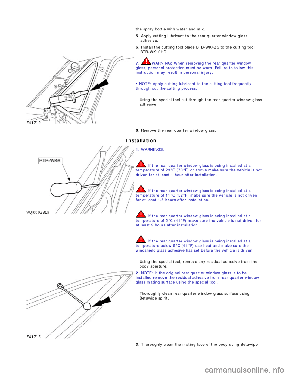
6. Install the cutting tool blade BTB-WK4ZS to the cutting tool
BTB-WK10HD.
7. WARNING: When removing the rear quarter window
glass, personal protec tion must be worn. Failure to follow this
instruction may result in personal injury.
• NOTE: Apply cutting lubricant to the cutting tool frequently
through out the cutting process.
Using the special tool cut throug h the rear quarter window glass
adhesive.
8. Remove the rear quarter window glass.
1. WARNINGS:
If the rear quarter window glass is being installed at a
temperature of 23°C (73°F) or abov e make sure the vehicle is not
driven for at least 1 hour after installation.
If the rear quarter window glass is being installed at a
temperature of 11°C (52°F) make sure the vehicle is not driven
for at least 1.5 hours after installation.
If the rear quarter window glass is being installed at a
temperature of 5°C (41°F) make su re the vehicle is not driven for
at least 2 hours after installation.
If the rear quarter window glass is being installed at a
temperature below 5°C (41°F) use heat and make sure the
windshield glass adhesive has set before the vehicle is driven.
Using the special tool, remove any residual adhe sive from the
body aperture.
2. NOTE: If the original rear qu arter window glass is to be
installed remove the residual ad hesive from rear quarter window
glass mating surface using the special tool.
Thoroughly clean rear quarte r window glass surface using
Betawipe spirit.
3. Thoroughly clean the mating face of the body using Betawipe
Page 2207 of 2490
12. Pass free end of cheese wire through penetration and install
second cutting handle.
13. WARNING: When removing the rear window glass,
personal protection must be worn. Failure to follow this
instruction may result in personal injury.
• CAUTIONS:
Make sure the ch eese wire cannot contact the paintwork
while the the rear window glass ad hesive is being cut. Failure to
follow this instruction may result in damage to the vehicle.
When cutting, do not allow ch eese wire to contact edge of
window glass as this will crack the window glass.
• NOTE: Apply cutting lubricant to the cheese wire frequently
through out the cutting process.
With assistance and exercising care to avoid damaging the
paintwork, cut around the re ar window glass commencing
upwards and along the top.
14. Install the lifting handles to the windshield glass, and with
assistance carefully remove th e rear window glass from the
vehicle.
Page 2208 of 2490
Installation
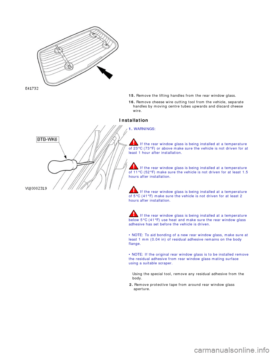
15. Remove the lifting handles from the rear window glass.
16. Remove cheese wire cutting tool from the vehicle, separate
handles by moving centre tubes upwards and discard cheese
wire.
1. WARNINGS:
If the rear window glass is being installed at a temperature
of 23°C (73°F) or above make sure the vehicle is not driven for at
least 1 hour after installation.
If the rear window glass is being installed at a temperature
of 11°C (52°F) make sure the vehicl e is not driven for at least 1.5
hours after installation.
If the rear window glass is being installed at a temperature
of 5°C (41°F) make su re the vehicle is not driven for at least 2
hours after installation.
If the rear window glass is being installed at a temperature
below 5°C (41°F) use heat and ma ke sure the rear window glass
adhesive has set before the vehicle is driven.
• NOTE: To aid bonding of a new re ar window glass, make sure at
least 1 mm (0.04 in) of residual adhesive remains on the body
flange.
• NOTE: If the original rear window glass is to be installed remove
the residual adhesive from rear window glass mating surface
using a suitable scraper.
Using the special tool, remove any residual adhe sive from the
body.
2. Remove protective tape from around rear window glass
aperture.
Page 2214 of 2490
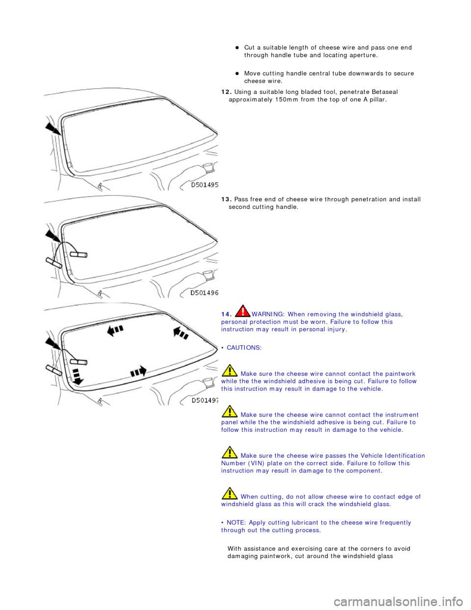
Cut a suitable length of cheese wire and pass one end
through handle tube and locating aperture.
Move cutting handle central tube downwards to secure
cheese wire.
12. Using a suitable long bladed tool, penetrate Betaseal
approximately 150mm from the top of one A pillar.
13. Pass free end of cheese wire through penetration and install
second cutting handle.
14. WARNING: When removing the windshield glass,
personal protection must be worn. Failure to follow this
instruction may result in personal injury.
• CAUTIONS:
Make sure the ch eese wire cannot contact the paintwork
while the the windshield adhesive is being cut. Failure to follow
this instruction may result in damage to the vehicle.
Make sure the cheese wire cannot contact the instrument
panel while the the windshield adhesive is being cut. Failure to
follow this instruction may result in damage to the vehicle.
Make sure the cheese wire passes the Vehicle Identification
Number (VIN) plate on the correct side. Failure to follow this
instruction may result in damage to the component.
When cutting, do not allow ch eese wire to contact edge of
windshield glass as this will crack the windshield glass.
• NOTE: Apply cutting lubricant to the cheese wire frequently
through out the cutting process.
With assistance and exercising care at the corners to avoid
damaging paintwork, cut around the windshield glass
Page 2328 of 2490
Roof Opening Panel - Roof Opening Panel
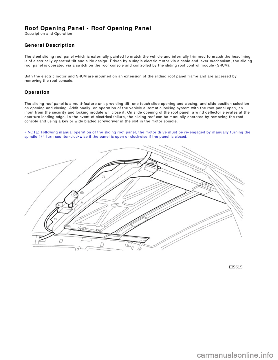
Description and Operation
General Description
The steel sliding roof panel which is externally painted to ma tch the vehicle and internally trimmed to match the headlining,
is of electrically operated tilt and slide design. Driven by a single electric motor via a cable and lever mechanism, the slidi ng
roof panel is operated via a switch on the roof console and controlled by the sliding roof control module (SRCM).
Both the electric motor and SRCM are mounted on an extens ion of the sliding roof panel frame and are accessed by
removing the roof console.
Operation
The sliding roof panel is a multi-feature unit providing tilt, one touch slide opening and closing, and slide position selectio n
on opening and closing. Additi onally, on operation of the vehicle automatic locking system with the roof panel open, an
input from the security and lockin g module will close it. On slide opening of the roof panel, a wind deflector elevates at the
aperture leading edge. In the event of electrical failure, the sliding roof can be manually operated by removing the roof
console and using a key or wide bladed scre wdriver in the slot in the motor spindle.
• NOTE: Following manual operation of the sliding roof panel, the motor drive must be re-engaged by manually turning the
spindle 1/4 turn counter-clockwise if the panel is open or clockwise if the panel is closed.