1998 JAGUAR X308 service
[x] Cancel search: servicePage 1050 of 2490
Power Assisted Steering Pump Drive
The power assisted steering pump pull
ey
is located on the left side, above the air-conditioning compressor.
Generator Dr
ive
The genera
tor is fitted on the
right hand accessory mounting.
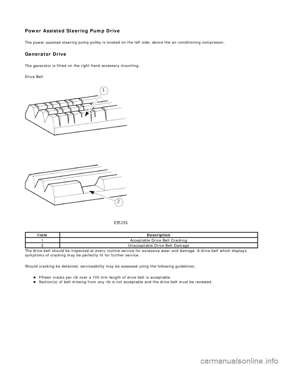
Drive Belt
The drive belt should be inspected at every routine service for excessive wear and damage. A drive belt which displays
symptoms of cracking may be pe rfectly fit for further service.
Should cracking be detected, serviceability ma y be assessed using the following guidelines:
Fi
fteen cracks per rib over a 100 mm le
ngth of drive belt is acceptable.
Sec
tion(s) of belt missing from an
y rib is not acceptable and the drive belt must be renewed.
Ite
m
De
scr
iption
1Ac
c
eptable Drive Belt Cracking
2Unacceptable Drive Belt Damage
Page 1072 of 2490
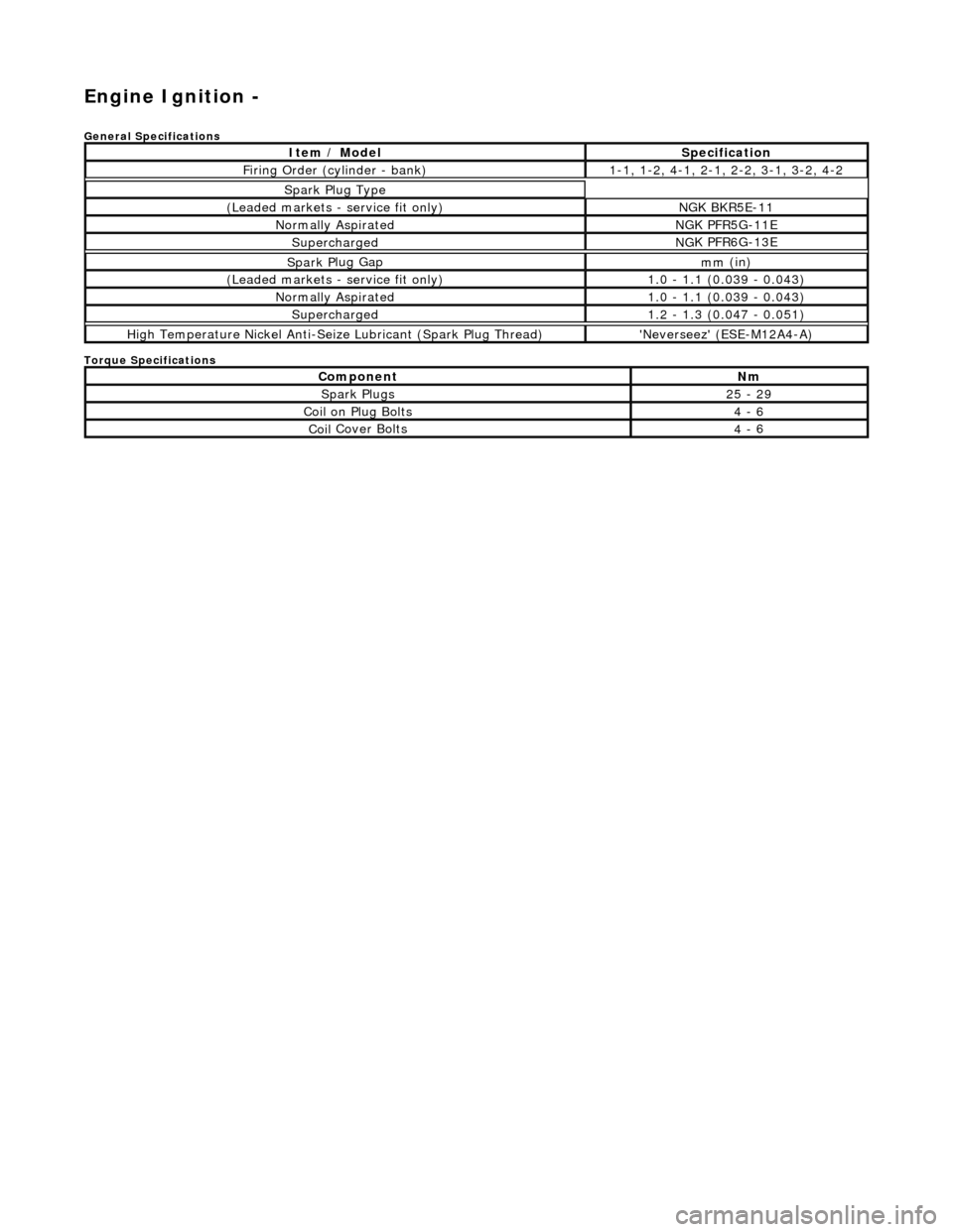
Engine Ignition -
General Spe
cifications
Torque Specifications
Ite
m / Model
Sp
ecification
F
i
ring Order (cylinder - bank)
1-
1
, 1-2, 4-1, 2-1, 2-2, 3-1, 3-2, 4-2
Spark P
l
ug Type
(Leaded markets -
service fit only)NGK BK
R5E-11
N
ormal
ly Aspirated
NG
K PF
R5G-11E
SuperchargedNG
K PF
R6G-13E
Spark P
l
ug Gap
mm
(i
n)
(Leaded markets -
service fit only)1.0 -
1.1 (0.039 - 0.043)
N
ormal
ly Aspirated
1.
0 -
1.1 (0.039 - 0.043)
Supercharged1.
2 -
1.3 (0.047 - 0.051)
High
Tem
perature Nickel Anti-Seize
Lubricant (Spark Plug Thread)
'Ne
verseez' (ESE-M12A4-A)
Com
p
onent
Nm
Spark P
l
ugs
25
-
29
Coil
on
Plug Bolts
4 -
6
Co
il
Cover Bolts
4 -
6
Page 1078 of 2490
• NO
TE: When performing electrical voltag
e or resistance tests, always use a digital multimeter (DMM) accurate to 3
decimal places, and with an up-t o-date calibration certificate. When testing resistance, always take the resistance of the
DMM leads into account.
• NOTE: Check and rectify basic faults before beginning diagnostic ro utines involving pinpoint tests.
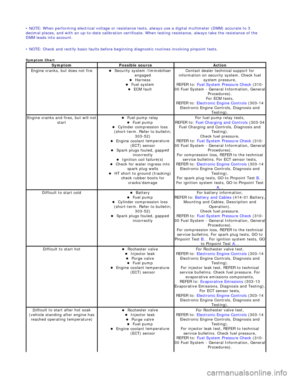
Sym
ptom Chart
Sy
m
ptom
Possib
l
e source
Acti
o
n
Engine
cranks, but does
not fire
Secu
rit
y system /Immobiliser
engaged
Harness Fue l
system
ECM fault
Contact deal er techni
cal support for
information on security system. Check fuel
system pressure,
REFER to: Fuel System Pressure Check
(310
-
00 Fuel System - Genera l Information, General
Procedures).
For ECM tests,
REFER to: Electronic Engine Controls
(303
-14
Electronic Engine Co ntrols, Diagnosis and
Testing).
Engine cranks and
fi
res, but will not
start
Fu
el pump relay
Fuel
pump
Cyl
i
nder compression loss
(short-term. Refer to bulletin; 303-52)
Engine coolan t
temperature
(ECT) sensor
Spark plugs fouled, gapp
ed
incorrectly
Ignition coil fail
ure(s)
Check f
o
r water ingress into
spark plug wells
HT sho rt to ground (tracking)
check rubber
boots for
cracks/damage
Fo
r fuel pump relay tests,
REFER to: Fuel Charging and Controls
(303
-04
Fuel Charging and Controls, Diagnosis and Testing).
Check fuel pressure,
REFER to: Fuel System Pressure Check
(310
-
00 Fuel System - Genera l Information, General
Procedures).
For compression loss, REFER to the technical service bulletins. For ECT sensor tests,
REFER to: Electronic Engine Controls
(303
-14
Electronic Engine Co ntrols, Diagnosis and
Testing).
For spark plug tests, GO to Pinpoint Test B.
.
For ign i
tion system tests, GO to Pinpoint Test
A.
.
Diff
icult to start cold
Batt
ery Fuel
pump
Cyl
i
nder compression loss
(short-term. Refer to bulletin; 303-52)
Spark plugs fouled, gapp
ed
incorrectly
F o
r battery information,
REFER to: Battery and Cables
(414
-01 Battery,
Mounting and Cables, Description and Operation).
Check fuel pressure.
REFER to: Fuel System Pressure Check
(310
-
00 Fuel System - Genera l Information, General
Procedures).
For compression loss, REFER to the technical service bulletins. For spark plug tests, GO to
Pinpoint Test B.
. For ig
nition system tests, GO
to Pinpoint Test A.
.
Diff
icult to start hot
Roc
h
ester valve
Injec
t
or leak
Purge
val
ve
Fue
l
pump
Engine coolan
t
temperature
(ECT) sensor
F or R
ochester
valve test,
REFER to: Electronic Engine Controls
(303
-14
Electronic Engine Co ntrols, Diagnosis and
Testing).
For injector leak test, REFER to technical
service bulletins. Check fuel pressure. For evaporative emissions components,
REFER to: Evaporative Emissions
(303
-13
Evaporative Emissions, Diagnosis and Testing).
For ECT sensor tests,
REFER to: Electronic Engine Controls
(303
-14
Electronic Engine Co ntrols, Diagnosis and
Testing).
D iff
icult to start after hot soak
(vehicle standing after engine has reached operating temperature)
Roc h
ester valve
Injec
t
or leak
Purge
val
ve
Fue
l
pump
Engine coolan
t
temperature
(ECT) sensor
F or R
ochester
valve test,
REFER to: Electronic Engine Controls
(303
-14
Electronic Engine Co ntrols, Diagnosis and
Testing).
For injector leak test, REFER to technical service bulletins. Check fuel pressure,
REFER to: Fuel System Pressure Check
(310
-
00 Fuel System - Genera l Information, General
Procedures).
Page 1083 of 2490
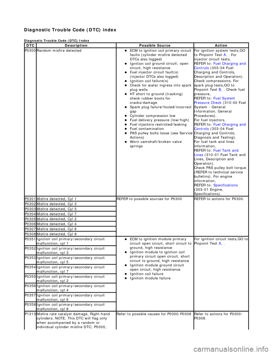
Diagnostic Trouble Code (D
TC) index
D
iagnostic Trouble Code (DTC) Index
DT
C
De
scription
Possib
le Source
Acti
on
P0300Ran
dom misfire detected
ECM t
o ignition coil primary circuit
faults (cylinder misfire detected
DTCs also logged)
Ignition coil
ground circuit; open
circuit, high resistance
F
uel injector circuit fault(s)
(injector DTCs also logged)
Ignition coil
failure(s)
Check f
or water ingress into spark
plug wells
HT sho
rt to ground (tracking)
check rubber boots for
cracks/damage
Spark plug
failure/fouled/incorrect
gap
Cy
linder compression low
F
uel delivery pressure (low/high)
F
uel injectors restricted/leaking
Fuel contamination
P
AS pulley bolts loose (see Service
Actions)
W
orn camshaft/broken valve
springs
For ign
ition system tests,GO
to Pinpoint Test A.
. For
inje
ctor circuit tests,
REFER to: Fuel Charging and
Controls (30
3-04 Fuel
Charging and Controls,
Description and Operation).
Check compressions. For
spark plug tests,GO to
Pinpoint Test B.
.
Check fuel
pressure,
REFER to: Fuel System
Pressure Check (31
0-00 Fuel
System - General
Information, General
Procedures).
For fuel injectors,
REFER to: Fuel Charging and
Controls (30
3-04 Fuel
Charging and Controls,
Diagnosis and Testing).
For fuel tank and lines
information,
REFER to: Fuel Tank and
Lin
es
(310-01 Fuel Tank and
Lines, Description and
Operation).
Check PAS pulley bolt torque
(REFER to technical service
bulletins). For engine
information,
REFER to: Specifications
(3
03-01 Engine,
Specifications).
P0301Misfire
detected, Cyl 1
R
EFER to possible sources for P0300
R
EFER to actions for P0300.
P0302Misfire
detected, Cyl 3
P0303Misfire
detected, Cyl 5
P0304Misfire
detected, Cyl 7
P0305Misfire
detected, Cyl 2
P0306Misfire
detected, Cyl 4
P0307Misfire
detected, Cyl 6
P0308Misfire
detected, Cyl 8
P0351Igni
tion coil primary/secondary circuit
malfunction, cyl 1
ECM to
ignition module primary
circuit open circuit, short circuit to
ground, high resistance
Igni
tion module to ignition coil
primary circuit open circuit, short
circuit to ground, high resistance
Ignition modu
le ground circuit
open circuit, hi gh resistance
Ignition coil
failure
Ignition modul
e failure
F
or ignition circuit tests,GO to
Pinpoint Test A.
.
P0352Igni
tion coil primary/secondary circuit
malfunction, cyl 3
P0353Igni
tion coil primary/secondary circuit
malfunction, cyl 5
P0354Igni
tion coil primary/secondary circuit
malfunction, cyl 7
P0355Igni
tion coil primary/secondary circuit
malfunction, cyl 2
P0356Igni
tion coil primary/secondary circuit
malfunction, cyl 4
P0357Igni
tion coil primary/secondary circuit
malfunction, cyl 6
P0358Igni
tion coil primary/secondary circuit
malfunction, cyl 8
P1313Misfire rate
catalyst damage, Right-hand
cylinders. NOTE. This DTC will flag only
when accompanied by a random or
individual cylinder misfire DTC; P0300,
R
efer to possible causes for P0300-P0308
R
efer to actions for P0300-
P0308.
Page 1092 of 2490
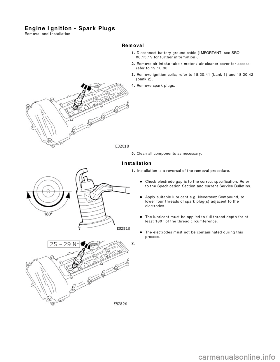
Engine Ignition - Spark
Plugs
Re
mo
val and Installation
Remov
a
l
Installation
1.
Disc onne
ct battery ground cable (IMPORTANT, see SRO
86.15.19 for further information).
2. Remove air intake tube / meter / air cleaner cover for access;
refer to 19.10.30.
3. Remove ignition coils; refer to 18.20.41 (bank 1) and 18.20.42
(bank 2).
4. Re
move spark plugs.
5. Clean all components as necessary.
1. Installation
is a reversal
of the removal procedure.
Check ele
ctrode gap is to the
correct specification. Refer
to the Specification Section and current Service Bulletins.
Apply su
itable lubricant e.
g. Neverseez Compound, to
lower four threads of spark plug(s) adjacent to the
electrodes.
The lubrican t must be applied
to full thread depth for at
least 180° of the thread circumference.
T h
e electrodes must not be
contaminated during this
process.
2.
Page 1154 of 2490
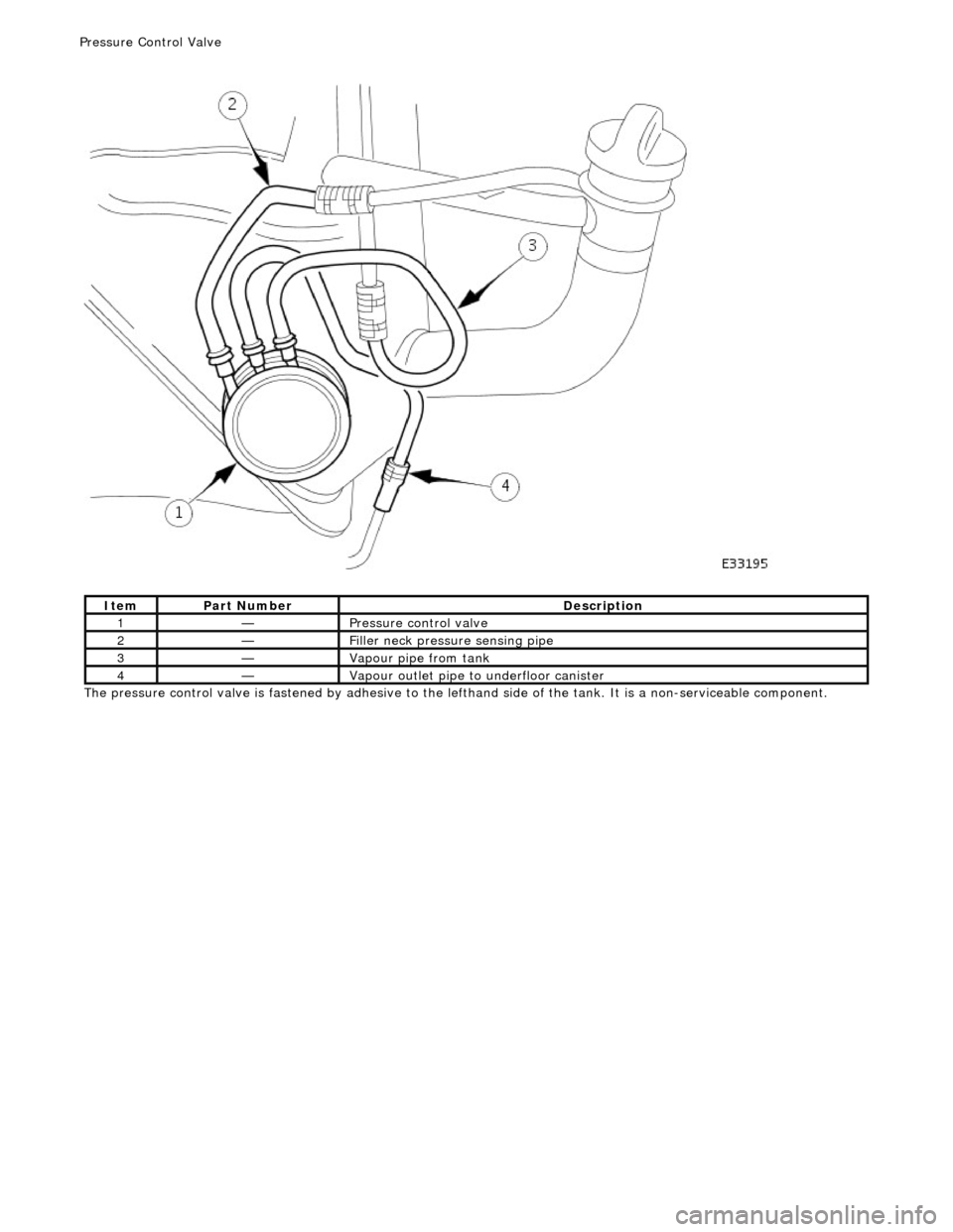
The pressure co ntrol val
ve is fa
stened by adhesive to the lefthand side of the tank. It is a non-serviceable component.
Ite
m
Par
t
Number
De
scr
iption
1—Pressure control
valve
2—Fill
er neck pressure sensing pipe
3—Vapour pipe fro
m ta
nk
4—Vapour outlet pipe to u
n
derfloor canister
P
r
essure Control Valve
Page 1179 of 2490
generates a signal when th
e dr
ive plate passes the sensor
sen
ds the ECM signals indicating crankshaft position and engine speed
is e
ssential for calculating spark timing
En
gine Coolant Temperature (ECT) Sensor
sen
ds the ECM a signal indicating the temperature of the engine coolant
is a t
emperature dependent resistor with a negative temperature coefficient (resistance changes inversely with
respect to temperature) and is constantly monitored by the ECM
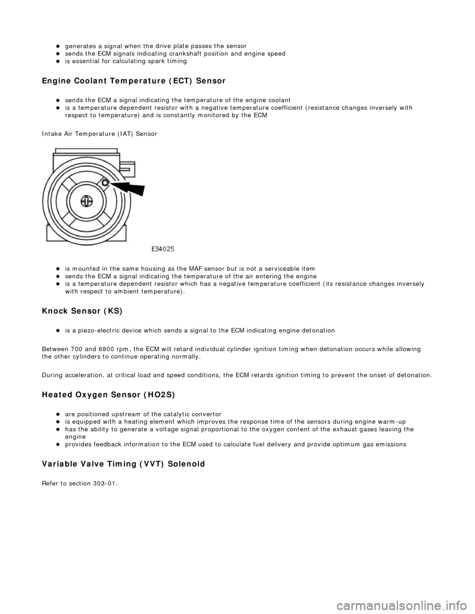
Intake Air Temperature (IAT) Sensor
is m
ounted in the same housing as the MA
F sensor but is not a serviceable item
sen
ds the ECM a signal indicating the temperature of the air entering the engine
is a t
emperature dependent resistor which has a negative
temperature coefficient (its resistance changes inversely
with respect to ambient temperature).
Knock S
ensor (KS)
is a pi
ezo-electric device which sends a signal
to the ECM indicating engine detonation
Between 700 and 6800 rpm, the ECM will retard individual cylinder ignition timing when detonation occurs while allowing
the other cylinders to continue operating normally.
During acceleration, at critical load and speed conditions, the ECM retards ignition timing to prevent the onset of detonation.
H
eated Oxygen Sensor (HO2S)
are
positioned upstream of the catalytic convertor
is equipped with
a heating element wh
ich improves the response time of the sensors during engine warm-up
h
as the ability to generate a voltage signal proportional to the oxygen content of the exhaust gases leaving the
engine
pr
ovides feedback information to the ECM used to calc
ulate fuel delivery and provide optimum gas emissions
Variable V
alve Timing (VVT) Solenoid
R
efer to section 303-01.
Page 1180 of 2490
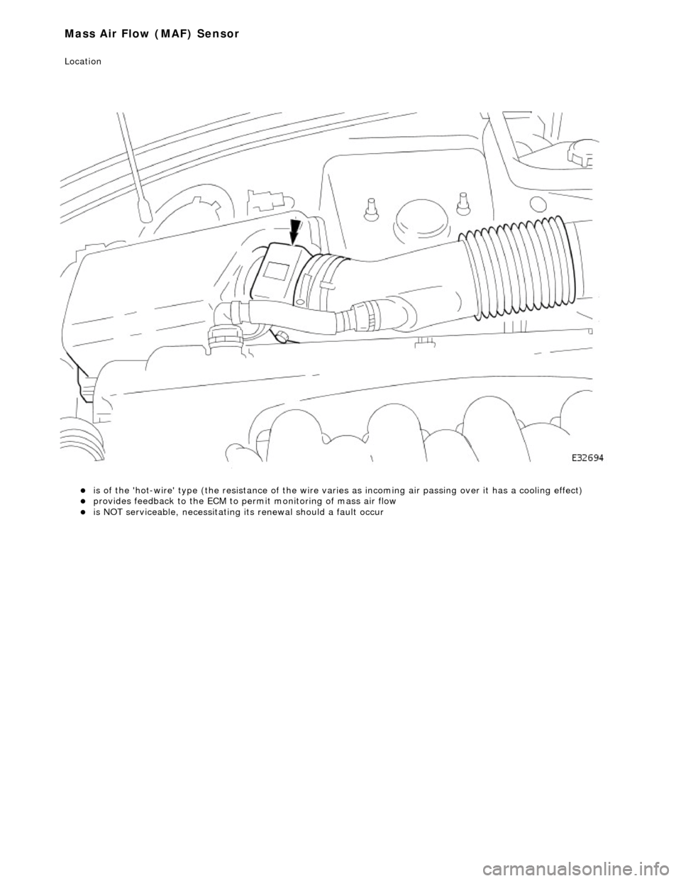
is
of the 'hot-wire' type (the resistan
ce of the wire varies as incoming air passing over it has a cooling effect)
provides f
eedback to the ECM to perm
it monitoring of mass air flow
is NO
T serviceable, necessitating its renewal should a fault occur
Mass Air Flo
w (MAF) Sensor
Location