1998 JAGUAR X308 service
[x] Cancel search: servicePage 2377 of 2490
Supplemental Restraint System - Side Air Bag Module
Removal and Installation
Removal
• WARNINGS:
A SIDE AIR BAG MUST ONLY BE RENEWED IF A FAULT FLAG HAS OCCURRED. IN THE EVENT OF SIDE AIR BAG
DEPLOYMENT DUE TO SIDE IMPACT, THE COMPLETE SEAT MUST BE RENEWED.
FOLLOWING TEN YEARS IN SERVICE, AN AIR BAG MO DULE MUST BE REMOVED AND DISPOSED OF IN THE
APPROVED MANNER, AND A NEW AIR BAG MUST BE FITTED.
FOLLOWING DISCONNECTION OF THE BATTERY, A PERIOD OF AT LEAST FIFTEEN MINUTES MUST BE ALLOWED TO
ELAPSE BEFORE DISCONNECTING THE SINGLE-POINT SENSIN G (SPS) UNIT AND AN ELAPSE OF 2 MINUTES ALLOWED
BEFORE DISCONNECTING ANY OTHER SUPPLEMENTARY RESTRAINT SYSTEM COMPONENT.
AIR BAGS CONTAIN A CHEMICAL IRRITANT. IF AN AIR BAG IS RENEWED, THE DISCARDED UNIT MUST BE DISPOSED
OF IN ACCORDANCE WITH CURRENT SAFETY PROCEDURES.
IN THE EVENT OF A FAULT RUPTURING THE 10A BATTERY SUPPLY FUSE (F4 LOCATED IN THE FUSE-BOX AT THE
DRIVER'S END OF THE FASCIA), THE FUSE MUST NOT BE RENEWED UNTIL THE AIRBAG/SRS SYSTEM HAS BEEN DE-
ACTIVATED. FUSES OF ANY OTHER VALUE MUST NEVER BE USED, AS THIS CAN CAUSE DISARM FAILURE.
1. Remove battery cover and disc onnect ground cable from
battery terminal. Refer to 86.15.19.
2. Remove seat from vehi cle. Refer to 76.70.01.
3. Remove seat back fini sher. Refer to 76.70.09.
4. Partially remove squab cover and foam pad for access. Refer to
76.70.15
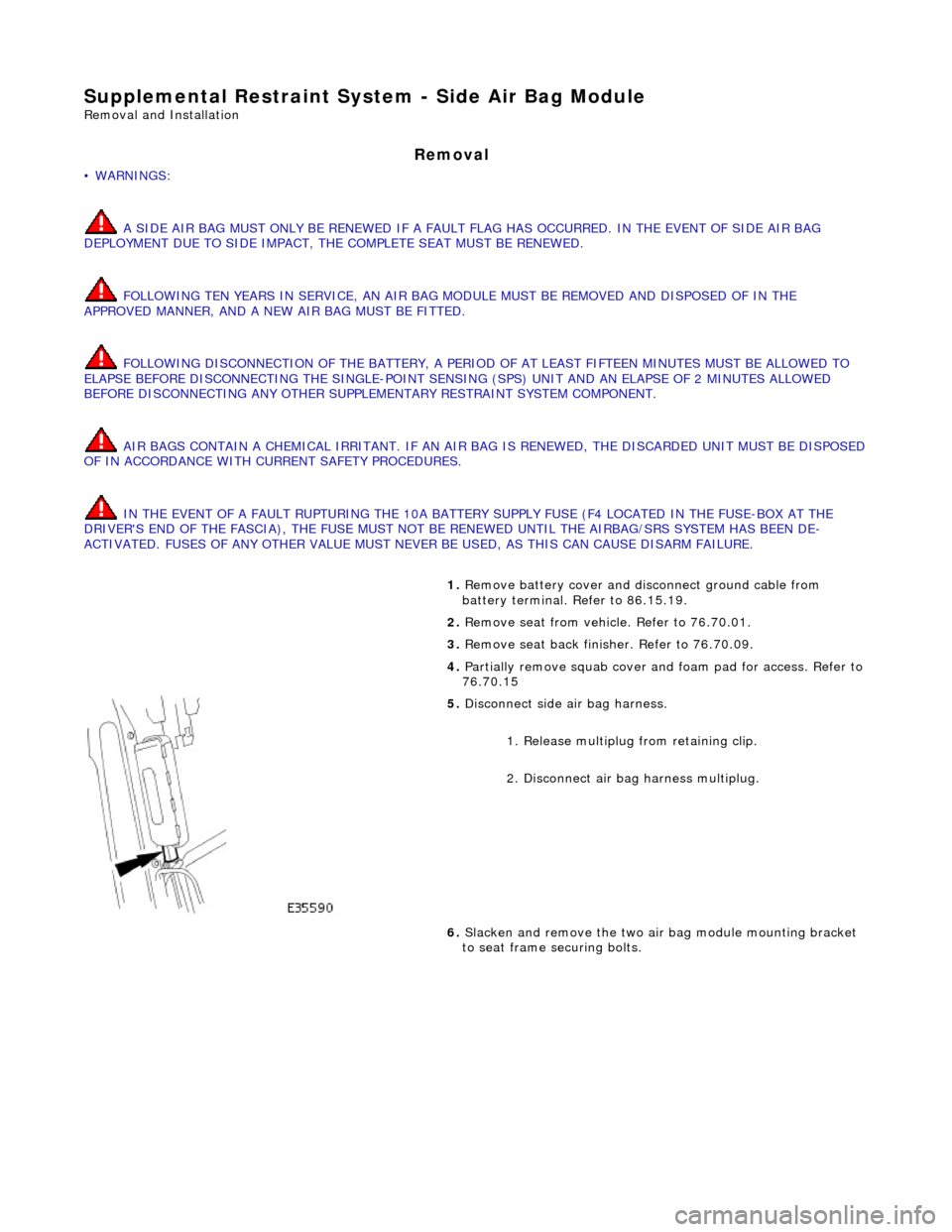
5. Disconnect side air bag harness.
1. Release multiplug from retaining clip.
2. Disconnect air ba g harness multiplug.
6. Slacken and remove the two air bag module mounting bracket
to seat frame securing bolts.
Page 2382 of 2490
Health and Safety
It is the duty of both employer and employee to ensure safe working conditions and practices. Correct safety procedures
and equipment must be applied to any potential hazards that are notified, or identified by an operator.
Employees must observe local legislation go verning working conditions and practices at all times and must always act in a
responsible manner in the workplace. In the event of personal injury resulting from any workshop activity, medical help
should be obtained as soon as poss ible. Self-treatment other than by first aid, should not be attempted.
WARNING: READ AND UNDERSTAND WORKING PRACTICE S CONCERNING CLIMATE CONTROL SYSTEMS, SECTION
412, WITH SPECIAL REGARD TO: REFRIGERANT MUST NEVE R BE DIRECTLY VENTED TO ATMOSPHERE. ALWAYS USE
JAGUAR APPROVED RECOVERY / RECYCLE / RECHARGE EQUI PMENT, WEAR SUITABLE EYE AND SKIN PROTECTION AND
OBSERVE ALL APPLICABLE SAFETY REQUIREMENTS.
With the constant introduction of new materials in the manufacture of vehicles, an awareness of the potential risks and
appropriate precauti ons is important.
Notification of Hazards
Symbols, which convey important information, will be positioned at the beginning of any specific operation or text. Standard symbols will be used where repairs or service procedures ar e detailed. All symbols will conform to standard ANSI Z535.3
(American National Standards Institute). The surround shape of the symbol will indicate the basis of the message to be
conveyed (see top three elements of ?) The icon depicting the message will be within the surrounding shape. Once
nominated the icon will retain its meaning.
POTENTIAL RISKS
Paint
Organic solvents, found in paints, may caus e damage or severe irritation to liver, kidneys, digestive tracts and respiratory
system if inhaled over long pe riods of time. Prolonged exposure to isocyanate s can cause lung sensitization with asthma-like symptoms developing on subsequent exposure to even low concentrations of isocyanates. Solvent inhalation can cause
dizziness or loss of consciousness and inhalation of spray dust and sanding debris may cause lung damage.
Spillage or splashes of solvents, paint ac tivators and additives can cause dermatitis or eye injury. Contact with peroxide or
acid catalysts can cause serious burns.
Applied Heat (Welding)
There is considerable risk of damage to eyes and skin if welding or flame cutting is attempted without using the correct
protective equipment. Many materials or fluids within vehicles are highly flammable and toxic and dangerous fumes may
also be liberated if heat is applied to expanded foam, corr osion protection, trim and seat materials, paints containing
isocyanates, and adhesive and sealing compounds.
When heated to a temperature of 300°C, polyurethane based compounds may liberate small quantities of isocyanate. Many
types of nitrogen containing chemicals ma y be liberated as breakdown products which can contain isocyanates, oxides of
nitrogen and hydrogen cyanide.
Potentially toxic or asphyxiant fumes and gases produced when welding include zinc oxide from zinc coated panels, and
ozone gas from the MIG process.
Metal Repair
There is considerable risk of damage to eyes, ears and skin wh en cutting, forming, or dressing metal. Soldering operations
can also be hazardous due to heat generated fumes and the risk of skin contact with hot materials.
PRECAUTIONS
Page 2421 of 2490
Uni-Body, Subframe and Mounting System - Front Axle Crossmember
Removal and Installation
Removal
CAUTION: Replacement of nuts and bolts: Various thread-locking devices are used on nuts and bolts throughout the
vehicle. These devices restrict the number of times a nut or bolt can be used. See section 100-00 for information.
Special Tool(s)
Tie-Rod-End Taper Separator
211-098 (JD 100)
Engine Support Beam
303-021 (MS 53D)
1. Position vehicle on a four-post lift.
2. Raise front of vehicle and support on stands.
3. Remove battery cover and disc onnect ground cable from
battery terminal. Refer to section 86.15.15.
4. Open hood to service position, and fit covers to fenders.
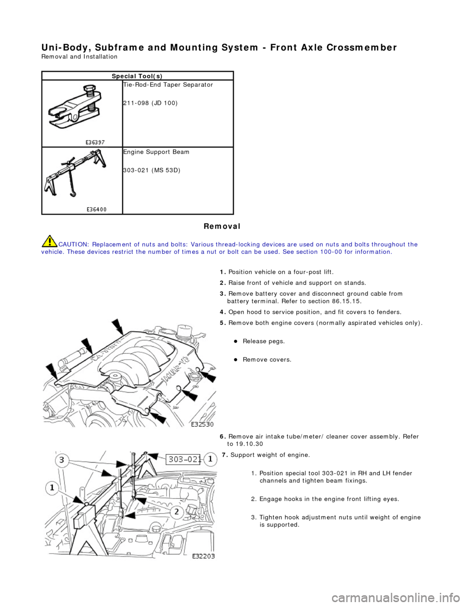
5. Remove both engine covers (nor mally aspirated vehicles only).
Release pegs.
Remove covers.
6. Remove air intake tube/meter/ cleaner cover assembly. Refer
to 19.10.30
7. Support weight of engine.
1. Position special tool 303-021 in RH and LH fender channels and tighte n beam fixings.
2. Engage hooks in the en gine front lifting eyes.
3. Tighten hook adjustment nuts until weight of engine is supported.
Page 2439 of 2490
Uni-Body, Subframe and Mounting System - Front Axle Crossmember
Front Bushing
Removal and Installation
Removal
CAUTION: Replacement of nuts and bolts: Various thread-locking devices are used on nuts and bolts throughout the
vehicle. These devices restrict the number of times a nut or bolt can be used. See Section 100-00 for information.
Special Tool(s)
Engine Support Beam
303-021 (MS 53D)
Front Camber Tie-down Link
204-114 (JD 133)
1. Position vehicle on a four-post lift.
2. Remove ignition key and en gage steering column lock.
3. Open hood to service position, and fit covers to fenders.
4. Remove battery cover and disc onnect ground cable from
battery terminal. Refer to 86.15.19.
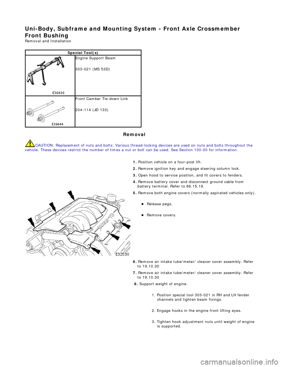
5. Remove both engine covers (nor mally aspirated vehicles only).
Release pegs.
Remove covers.
6. Remove air intake tube/meter/ cleaner cover assembly. Refer
to 19.10.30
7. Remove air intake tube/meter/ cleaner cover assembly. Refer
to 19.10.30
8. Support weight of engine.
1. Position special tool 303-021 in RH and LH fender channels and tighte n beam fixings.
2. Engage hooks in the en gine front lifting eyes.
3. Tighten hook adjustment nuts until weight of engine is supported.
Page 2450 of 2490
Uni-Body, Subframe and Mounting System - Front Axle Crossmember
Front Bushing Heat Shield
Removal and Installation
Removal
CAUTION: Replacement of nuts and bolts: Various thread-locking devices are used on nuts and bolts throughout the
vehicle. These devices restrict the number of times a nut or bolt can be used. See Section 100-00 for information.
Special Tool(s)
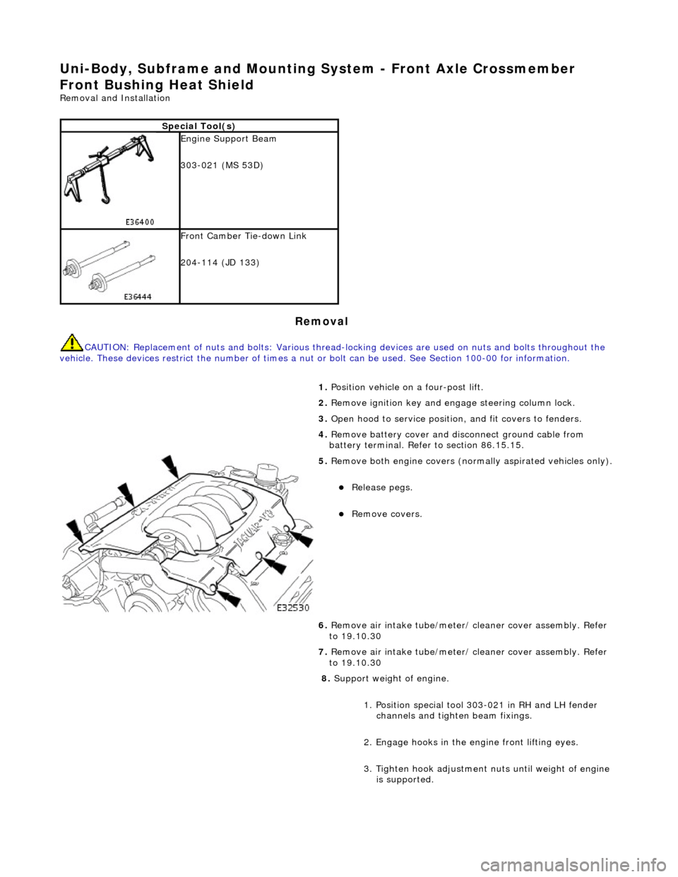
Engine Support Beam
303-021 (MS 53D)
Front Camber Tie-down Link
204-114 (JD 133)
1. Position vehicle on a four-post lift.
2. Remove ignition key and en gage steering column lock.
3. Open hood to service position, and fit covers to fenders.
4. Remove battery cover and disc onnect ground cable from
battery terminal. Refer to section 86.15.15.
5. Remove both engine covers (nor mally aspirated vehicles only).
Release pegs.
Remove covers.
6. Remove air intake tube/meter/ cleaner cover assembly. Refer
to 19.10.30
7. Remove air intake tube/meter/ cleaner cover assembly. Refer
to 19.10.30
8. Support weight of engine.
1. Position special tool 303-021 in RH and LH fender channels and tighte n beam fixings.
2. Engage hooks in the en gine front lifting eyes.
3. Tighten hook adjustment nuts until weight of engine is supported.
Page 2461 of 2490
Uni-Body, Subframe and Mounting System - Front Axle Crossmember Rear
Bushing
Removal and Installation
Removal
CAUTION: Replacement of nuts and bolts: Various thread-locking devices are used on nuts and bolts throughout the
vehicle. These devices restrict the number of times a nut or bolt can be used. See section 100-00 for information.
Special Tool(s)
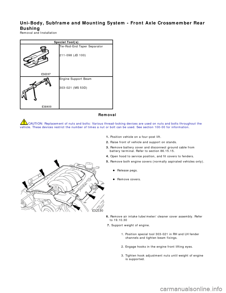
Tie-Rod-End Taper Separator
211-098 (JD 100)
Engine Support Beam
303-021 (MS 53D)
1. Position vehicle on a four-post lift.
2. Raise front of vehicle and support on stands.
3. Remove battery cover and disc onnect ground cable from
battery terminal. Refer to section 86.15.15.
4. Open hood to service position, and fit covers to fenders.
5. Remove both engine covers (nor mally aspirated vehicles only).
Release pegs.
Remove covers.
6. Remove air intake tube/meter/ cleaner cover assembly. Refer
to 19.10.30
7. Support weight of engine.
1. Position special tool 303-021 in RH and LH fender channels and tighte n beam fixings.
2. Engage hooks in the en gine front lifting eyes.
3. Tighten hook adjustment nuts until weight of engine is supported.