1998 JAGUAR X308 service
[x] Cancel search: servicePage 1753 of 2490
Climate Co
ntrol System - General In
formation - Climate Control System
Description an
d Operation
CAUTION: Observe all relevant safety requirements. Wear suitable eye and skin protection Do not mix HFC 134A and
CFC 12 refrigerants. Do not vent refrigerant directly to atmosphere and always use Jaguar approved recovery, recycle and
recharge equipment. Note the amount of recovered refrigerant; it will indicate the state of the system.
Working Practices
Be aware o
f, and comply with al
l health and safety requirements , whether they be legislative or common sense. This applies
to conditions set both for the operator and workshop.
Before commencing any repair or service procedure, disconnect the vehicle battery ground lead and protect the vehicle,
where appropriate, from dirt or damage.
Work in a well ventilated, clean and tidy area.
Keep all components and tools clean.
Recovery, recycle and recharge equipment must meet, or ex ceed, the requirements detailed in the Specification sub-
section.
Handling Refrigerant
We
ar eye protection at all times. Use gloves and keep all
skin covered that may come into contact with refrigerant.
Should refrigerant come into co ntact with eyes or skin, wash the affected area with cool water and seek medical advice; do
not attempt to treat the condition yourself.
Avoid breathing refrigerant vapor; it may cause irritation to the respiratory system.
CAUTION: Never use high pressure comp ressed air to flush out a system. Under certain ci rcumstances a combination
of HFC 134A refrigerant, compressed air and a source of combus tion (welding and brazing operations in the vicinity), may
result in an explosion and the release of potentially toxic compounds.
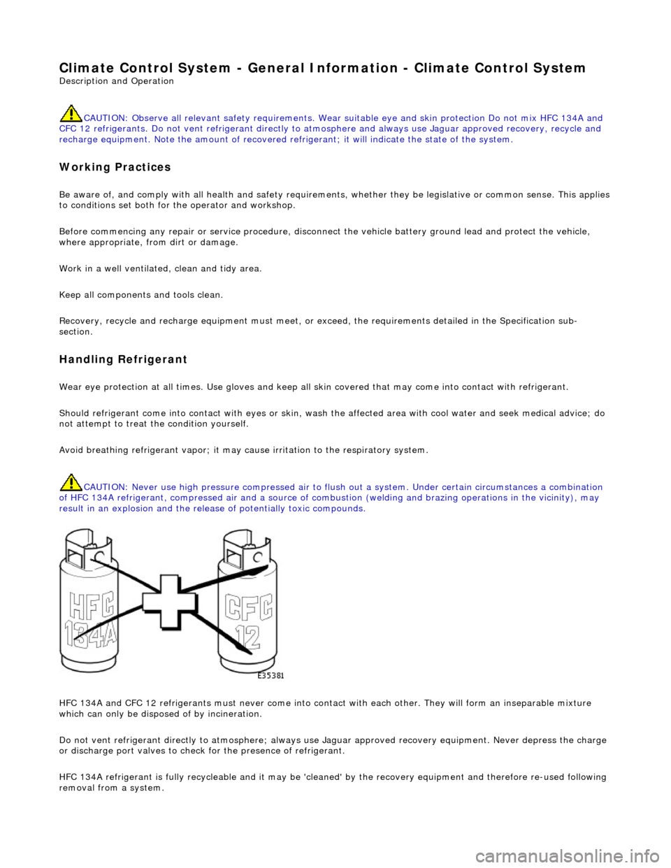
HFC 134A and CFC 12 refrigerants must neve r come into contact with each other. They will form an inseparable mixture
which can only be disposed of by incineration.
Do not vent refrigerant directly to atmo sphere; always use Jaguar approved recove ry equipment. Never depress the charge
or discharge port valves to check for the pr esence of refrigerant.
HFC 134A refrigerant is fully recycleable and it may be 'cleaned' by the recovery equipment and therefore re-used following
removal from a system.
Page 1761 of 2490
Climate Co
ntrol System - General In
formation - Air Conditioning (A/C)
System Check - Re tail Procedure
Gen
eral Procedures
E
vacuating the Manifold Gauge Set
Connecting the Manifold Gauge Set
C
AUTION: Only use hoses with connectors wh
ich are dedicated to HFC 134A charge ports.
Stabilizing the System
1.
At
tach the center (service) hose to a vacuum pump and start
the pump. Open fully both high and low valves and allow the
vacuum to remove air and mois ture from the manifold set for
at least five minutes.
CAUTION: It is imperative th at the vacuum pump is not
subjected to a positi ve pressure of any degree. Therefore the
pump must be fitted wi th an isolation valve at the center (service
hose) connection and this valve mu st be closed before the pump
is switched off. This operation replaces the 'purge' procedure used
on previous systems. Observe the manufacturer's
recommendation with regard to vacuum pump oil changes.
Turn the vacuum pump off and isol ate it from the center service
hose but do not open the hose to atmosphere.
1. Att
achment of the hose quick release connectors to the high
and low side system ports is stra ightforward, provided that the
high and low valves are closed and the system is NOT
operational.
WARNING: UNDER NO CIRCUMSTANCES SHOULD THE
CONNECTIONS BE MADE WITH THE SYSTEM IN OPERATION OR
THE VALVES OPEN. SHOULD THE VALVES BE OPEN AND A
VACUUM PUMP OR REFRIGERANT CONTAINER ATTACHED, AN
EXPLOSION COULD OCCUR AS A RESULT OF HIGH PRESSURE
REFRIGERANT BEING FORCED BACK INTO THE VACUUM PUMP OR
CONTAINER.
Assessment of system operating efficiency and fault
classification may be achieved by using the facilities on your
Recovery / Recharging / Recycling station, follow the
manufacturer's instructions implicitly and observe all safety
considerations.
1. Accurate test gauge data wi
ll on
ly be attained if the system
temperatures and pressures are stabilized.
E
nsure that equipment and hoses cannot come into
contact with engine moving parts or sources of heat.
It is recommended th at a free standing air
mover is placed
in front of the vehicle to provide air flow through the
condenser / cooling system.
St
art the engine, allow it to attain normal working
temperature and set at fast idle (typically 1200 to 1500
rpm).
Select full
air condit
ioning performance.
With
all temperatures and pres
sures stable, or displaying
symptoms of faults; begin relevant test procedures.
Page 1762 of 2490
Climate Control System - General Infor
mation - Air Conditioning (A/C)
System Recovery, Evacuation and Charging
Gen e
ral Procedures
Recover / Reclaim
Ev
acuation
Charging
1.
CAUTIO
N: Read the procedures and instructions supplied
by the manufacturer of the air co nditioning service center before
commencing any process requiring the handling of refrigerant. In
addition to the manufacturer's in formation, observe all safety
precautions and advice deta iled in this section.
Disconnect battery ground lead; refer to 86.15.19.
2. Remove passenger side fi
rewall cover.
3. Remove driver side firewall cover.
4. Remove engine compar tment rear cover.
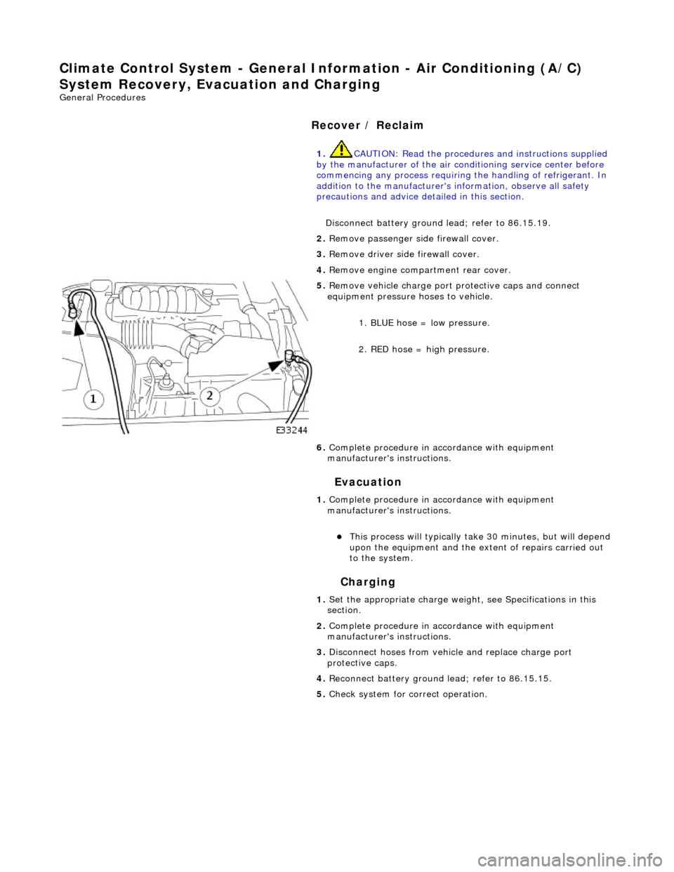
5. Re
move vehicle charge port
protective caps and connect
equipment pressure hoses to vehicle.
1. BLUE hose = low pressure.
2. RED hose = high pressure.
6. Complete procedure in ac cordance with equipment
manufacturer's instructions.
1. Complete procedure in ac cordance with equipment
manufacturer's instructions.
This proc
ess will typically ta
ke 30 minutes, but will depend
upon the equipment and the ex tent of repairs carried out
to the system.
1. Set the appropriate charge weight, see Specifications in this
section.
2. Complete procedure in ac cordance with equipment
manufacturer's instructions.
3. Disconnect hoses from vehicle and replace charge port
protective caps.
4. Reconnect battery ground lead; refer to 86.15.15.
5. Check system for correct operation.
Page 1764 of 2490
Clima
te Control System - General Inform
ation - Manifold Gauge Set Connection
Ge
neral Procedures
Mani
fol
d.
Low Side Pressure Gauge.
High Side Pressure Gauge.
1.
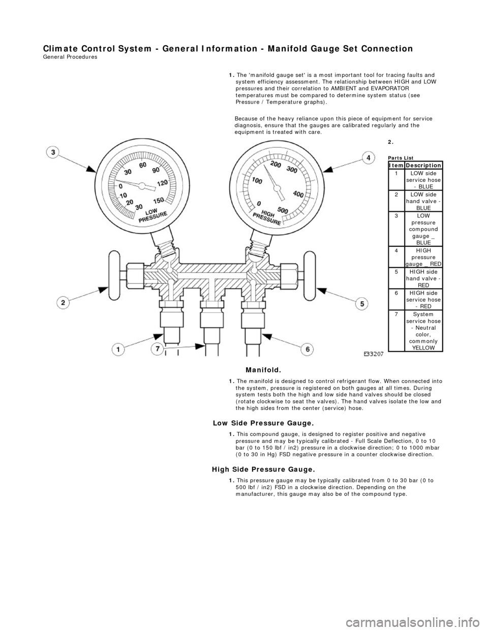
The 'ma
nifold gauge set' is a most important tool for tracing faults and
system efficiency assessment. The relationship between HIGH and LOW
pressures and their correlation to AMBIENT and EVAPORATOR
temperatures must be compared to determine system status (see
Pressure / Temperature graphs).
Because of the heavy reliance upon this piece of equipment for service
diagnosis, ensure that the gauges are calibrated regularly and the
equipment is treated with care.
2.
Parts
List
ItemDescri
ption1LOW side
serv
ice hose
- BLUE
2LOW side
ha
nd valve -
BL
UE3LOW
pres
sure
compound
gauge _ BLUE
4HI GH
pressure
gauge _ RED
5HI GH
side
hand valve -
RED6HI GH
side
service hose
- RED
7Sys t
em
service hose
- Neutral color,
commonly YELLOW
1. The manifold is designed to control refrigerant flow. When connected into
the system, pressure is registered on both gauges at all times. During
system tests both the high and low side hand valves should be closed
(rotate clockwise to seat the valves). The hand valves isolate the low and
the high sides from the center (service) hose.
1. This compound gauge, is designed to register positive and negative
pressure and may be typically calibrate d - Full Scale Deflection, 0 to 10
bar (0 to 150 lbf / in2) pressure in a clockwise direction; 0 to 1000 mbar
(0 to 30 in Hg) FSD negative pressu re in a counter clockwise direction.
1. This pressure gauge may be typically calibrated from 0 to 30 bar (0 to
500 lbf / in2) FSD in a clockwise direction. Depending on the
manufacturer, this gauge may also be of the compound type.
Page 1801 of 2490
Condenser:
Multi-pass fin-over-tube type, mounted in front of the engine cooling pack and directly to the radiator.
Pressure (Bitron) switch:
Located in the discharge pipe. Provides a signal, via the A/CCM, to th e ECM, to disengage the compressor clut ch should the refrigerant pressure be
< 2 bar or > 30 bar.
Provides a hard-wired signal to the ECM, to switch the cool ing fans to HIGH speed at 22 bar rising pressure and to
LOW speed at 17,5 bar falling pressure.
Provides a hard-wired signal to the ECM, to switch the radiator cooling fans to LOW speed at 12 bar rising pressure
and to switch the fans OFF at 8 bar falling pressure.
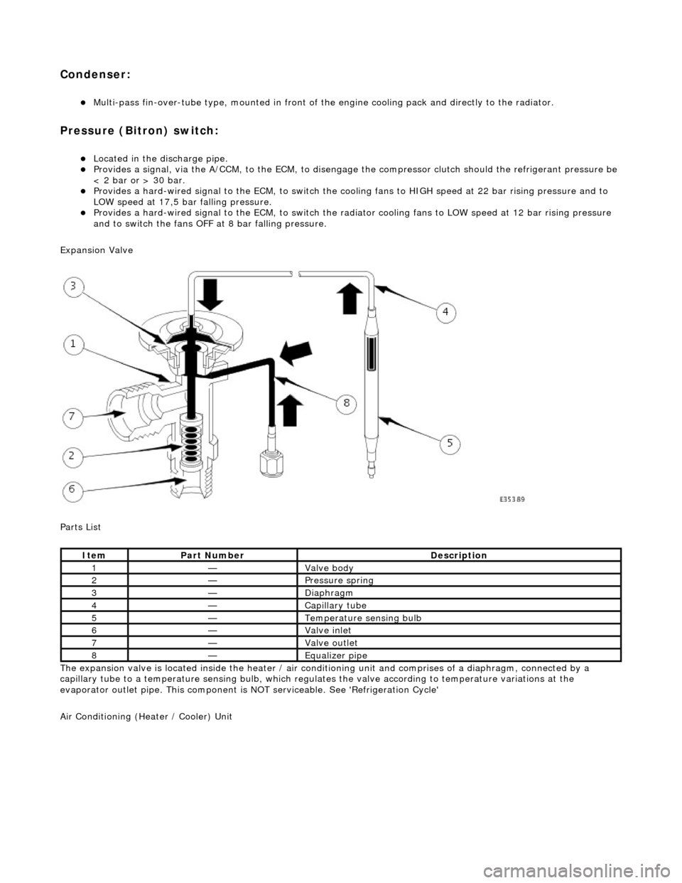
Expansion Valve
Parts List
The expansion valve is located inside the heater / air conditioning unit and comprises of a diaphragm, connected by a
capillary tube to a temperat ure sensing bulb, which regulates the valve according to temperature variations at the
evaporator outlet pipe. This component is NOT serviceable. See 'Refrigeration Cycle'
Air Conditioning (Heater / Cooler) Unit
ItemPart NumberDescription
1—Valve body
2—Pressure spring
3—Diaphragm
4—Capillary tube
5—Temperature sensing bulb
6—Valve inlet
7—Valve outlet
8—Equalizer pipe
Page 1808 of 2490
Air Conditioning - Condenser Core
Removal and Installation
Removal
1. Disconnect battery ground cable (IMPORTANT, see SRO
86.15.19 for further information).
2. Drain radiator coolant only; refer to 26.10.01 or (SC)
26.10.01.
3. Recover refrigerant from air co nditioning system; refer to
82.30.30.
4. Release both gas struts, set the engine cover fully forward to
the service access position an d support with a wooden (or
similar) strut.
5. CAUTION: Take care not to damage hood or radiator
grille.
Remove twin fan and motor as sembly; refer to 26.25.12.
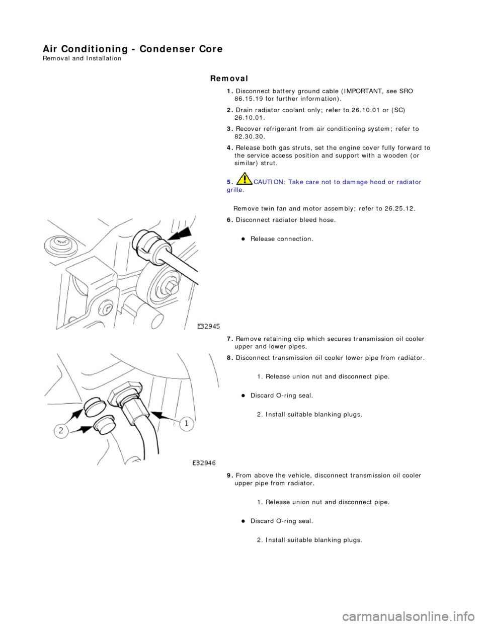
6. Disconnect radiator bleed hose.
Release connection.
7. Remove retaining clip which secures transmission oil cooler
upper and lower pipes.
8. Disconnect transmission oil cooler lower pipe from radiator.
1. Release union nut and disconne ct pipe.
Discard O-ring seal.
2. Install suitable blanking plugs.
9. From above the vehicle, discon nect transmission oil cooler
upper pipe from radiator.
1. Release union nut and disconne ct pipe.
Discard O-ring seal.
2. Install suitable blanking plugs.
Page 1882 of 2490
Generator and Regulator - Generator
Description and Operation
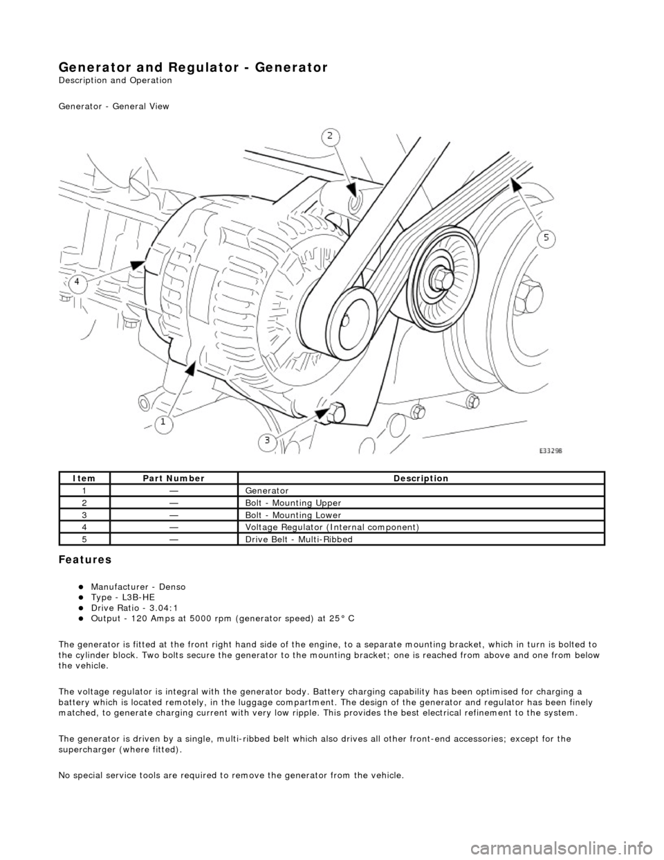
Generator - General View
Features
Manufacturer - Denso Type - L3B-HE Drive Ratio - 3.04:1 Output - 120 Amps at 5000 rpm (generator speed) at 25° C
The generator is fitted at the front right hand side of the engine, to a sepa rate mounting bracket, which in turn is bolted to
the cylinder block. Two bolts secure th e generator to the mounting bracket; one is reached from above and one from below
the vehicle.
The voltage regulator is integral with th e generator body. Battery charging capabi lity has been optimised for charging a
battery which is located remotely, in the luggage compartment. The design of the generator and regulator has been finely
matched, to generate charging current with very low ripple. This provides the best electrical refinement to the system.
The generator is driven by a single, multi-ribbed belt which also drives all other front-e nd accessories; except for the
supercharger (where fitted).
No special service tools are required to remove the generator from the vehicle.
ItemPart NumberDescription
1—Generator
2—Bolt - Mounting Upper
3—Bolt - Mounting Lower
4—Voltage Regulator (Internal component)
5—Drive Belt - Multi-Ribbed
Page 1883 of 2490
Belt tension is achieved by an automatic tensioner; neither the belt nor the tensioner require service apart from checking
the belt wear indicators at each normal service interval.
The minimum service life of the drive belt is 100,000 miles.
Never apply oil to the belt or to the belt tensioner.
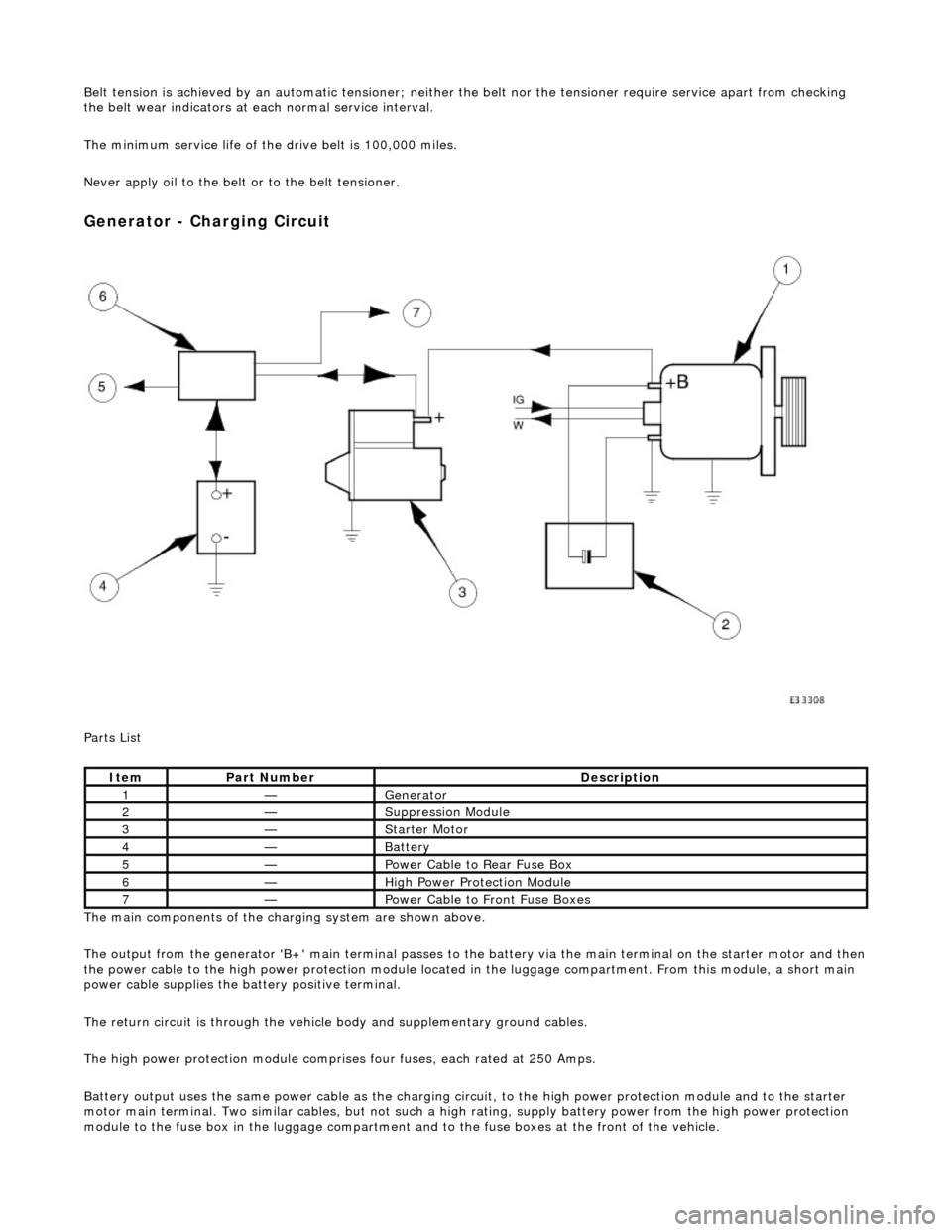
Generator - Charging Circuit
Parts List
The main components of the charging system are shown above.
The output from the generator 'B+' main te rminal passes to the battery via the main terminal on the starter motor and then
the power cable to the high power protection module located in the luggage compartment. From this module, a short main
power cable supplies the ba ttery positive terminal.
The return circuit is through the vehicle body and supplementary ground cables.
The high power protection mo dule comprises four fuses, each rated at 250 Amps.
Battery output uses the same power cable as the charging circ uit, to the high power protection module and to the starter
motor main terminal. Two similar cables, but not such a high rating, supply battery power from the high power protection
module to the fuse box in the luggage compartment an d to the fuse boxes at the front of the vehicle.
ItemPart NumberDescription
1—Generator
2—Suppression Module
3—Starter Motor
4—Battery
5—Power Cable to Rear Fuse Box
6—High Power Protection Module
7—Power Cable to Front Fuse Boxes