1998 JAGUAR X308 service
[x] Cancel search: servicePage 1190 of 2490
CAUTIO
N: When probing connectors to take
measurements in the course of the pinpoint tests, use the adaptor kit,
part number 3548-1358-00.
• NOTE: When performing electrical voltag e or resistance tests, always use a digital multimeter (DMM) accurate to 3
decimal places, and with an up-t o-date calibration certificate. When testing resistance, always take the resistance of the
DMM leads into account.
• NOTE: Check and rectify basic faults before beginning diagnostic ro utines involving pinpoint tests.
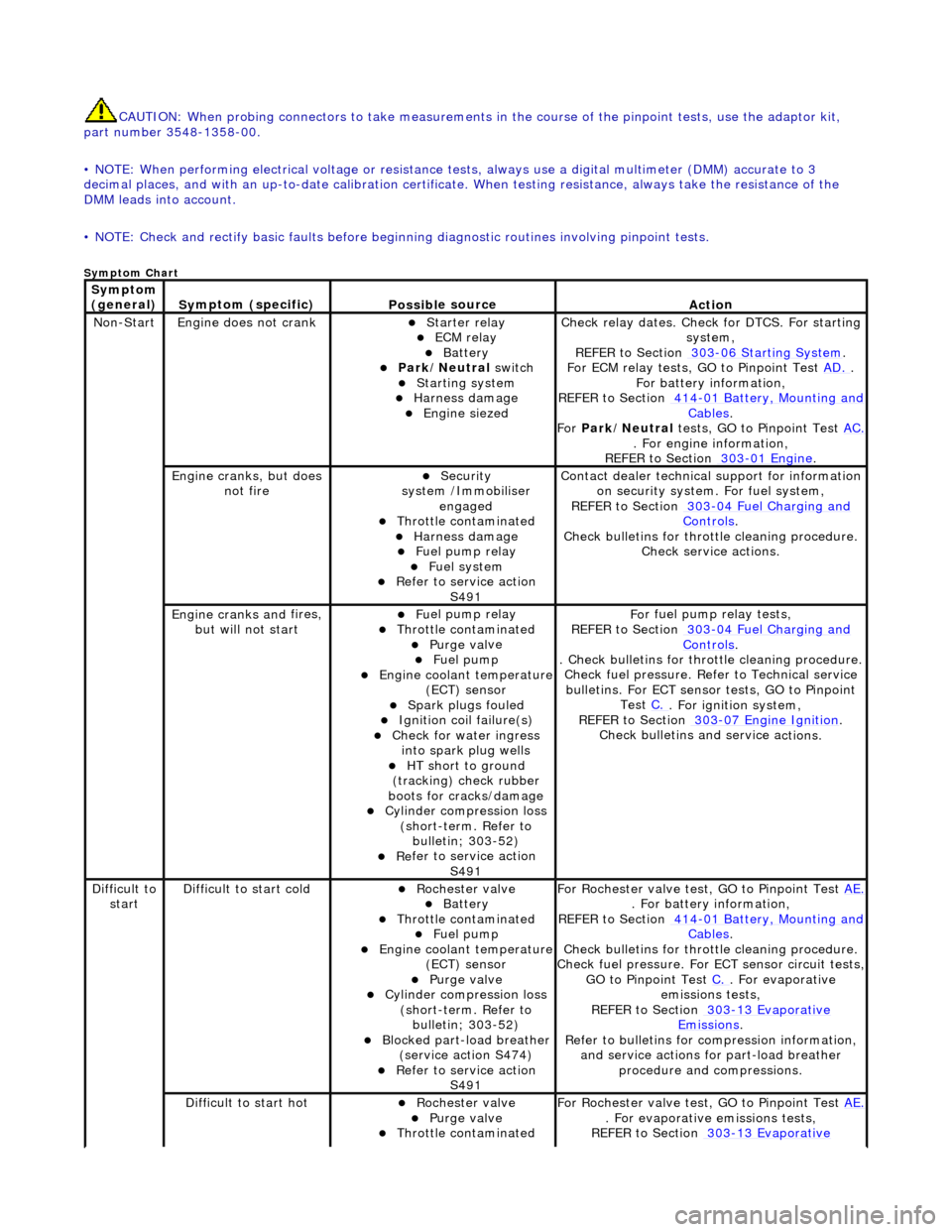
Sym
ptom Chart
Sym
ptom
(general)
S y
mptom (specific)
Possib
l
e source
Acti
o
n
No
n
-Start
Engine
does not cran
k
Starter relay ECM relay Batt
ery Park
/Neutral
switch
Starting system
Harness damage
Engine s
iezed
Check r
e
lay dates. Check
for DTCS. For starting
system,
REFER to Section 303
-06 Sta r
ting System
.
F or ECM
relay tests, GO to Pinpoint Test
AD.
.
F o
r battery information,
REFER to Section 414
-0 1
Battery, Mounting and
Cables.
Fo r
Park/Neutral tests, GO to Pinpoint Test AC.
. Fo
r engine information,
REFER to Section 303
-01 En
gine
.
Engine cranks, but does
not fireSecurity
syst
em /Immobiliser
engaged
Thr o
ttle contaminated
Harness damage
Fu
el pump relay
Fue
l
system
R
e
fer to service action
S491
Contact dealer techni
cal
support for information
on security system. For fuel system,
REFER to Section 303
-0 4
Fuel Charging and
Controls.
Check bull etins for throttl
e cleaning procedure.
Check service actions.
Engine cranks an d
fires,
but will not start
F u
el pump relay
Thr
o
ttle contaminated
Purge
val
ve
Fue
l
pump
Engine coolan
t
temperature
(ECT) sensor
Spark plugs
fouled
Ignition coil
fail
ure(s)
Check f
o
r water ingress
into spark plug wells
HT sh o
rt to ground
(tracking) check rubber
boots for cracks/damage
Cyli
nder compression loss
(short-term. Refer to bulletin; 303-52)
Re
fer to service action
S491
Fo
r fuel pump relay tests,
REFER to Section 303
-0 4
Fuel Charging and
Controls.
. Check bulletins for throttl
e cleaning procedure.
Check fuel pressure. Refe r to Technical service
bulletins. For ECT sensor tests, GO to Pinpoint Test C.
. Fo
r ignition system,
REFER to Section 303
-07 En
gine Ignition
.
Check bulletins an d service a
ctions.
Di
f
ficult to
start
D iff
icult to start cold
Roc
h
ester valve
Batt
ery Thro
ttle contaminated
Fue
l
pump
Engine coolan
t
temperature
(ECT) sensor
Purge val
ve
Cyl
i
nder compression loss
(short-term. Refer to bulletin; 303-52)
Blocked part-load breather (s
ervice action S474)
R
e
fer to service action
S491
For R
ochester valv
e test, GO to Pinpoint Test AE.
. Fo
r battery information,
REFER to Section 414
-0 1
Battery, Mounting and
Cables.
Check bull etins for throttl
e cleaning procedure.
Check fuel pressure. For ECT sensor circuit tests,
GO to Pinpoint Test C.
. F
or evaporative
emissions tests,
REFER to Section 303
-1 3
Evaporative
Emiss
i
ons
.
R e
fer to bulletins for co
mpression information,
and service actions for part-load breather procedure and compressions.
Diff
icult to start hot
Roc
h
ester valve
Purge
val
ve
Thr
o
ttle contaminated
F
or R
ochester valv
e test, GO to Pinpoint Test AE.
. F
or evaporative emissions tests,
REFER to Section 303
-1 3
Evaporative
Page 1191 of 2490
Fue
l pump
Engine coolan
t temperature
(ECT) sensor
Blocked part-load breather (
service action S474)
Injec
tor leak
Emiss
ions
.
Check bull
etins for throttle cleaning procedure.
Check fuel pressure. For ECT sensor circuit tests,
GO to Pinpoint Test C.
. Refer to Servi
ce action
S474 for part-load breather procedure. For
injector leak test, Refer to technical service bulletin 303-39.
D
ifficult to start after hot
soak (vehicle standing
after engine has reached operating temperature)
Roc
hester valve
Thr
ottle contaminated
Purge
valve
Fue
l pump
Engine coolan
t temperature
(ECT) sensor
Blocked part-load breather (
service action S474)
Injec
tor leak
Engine cranks too
fa
st/slow
Batt
ery
Starter relay Harness Cyl
inder compression loss
(NA short term only. Refer to technical service bulletin; 303-39)
R
efer to service action
S491
F
or battery information,
REFER to Section 414
-0
1 Battery, Mounting and
Cables.
F
or starting system.
REFER to Section 303
-06 Sta
rting System
.
R
efer to technical servic
e bulletins and service
actions.
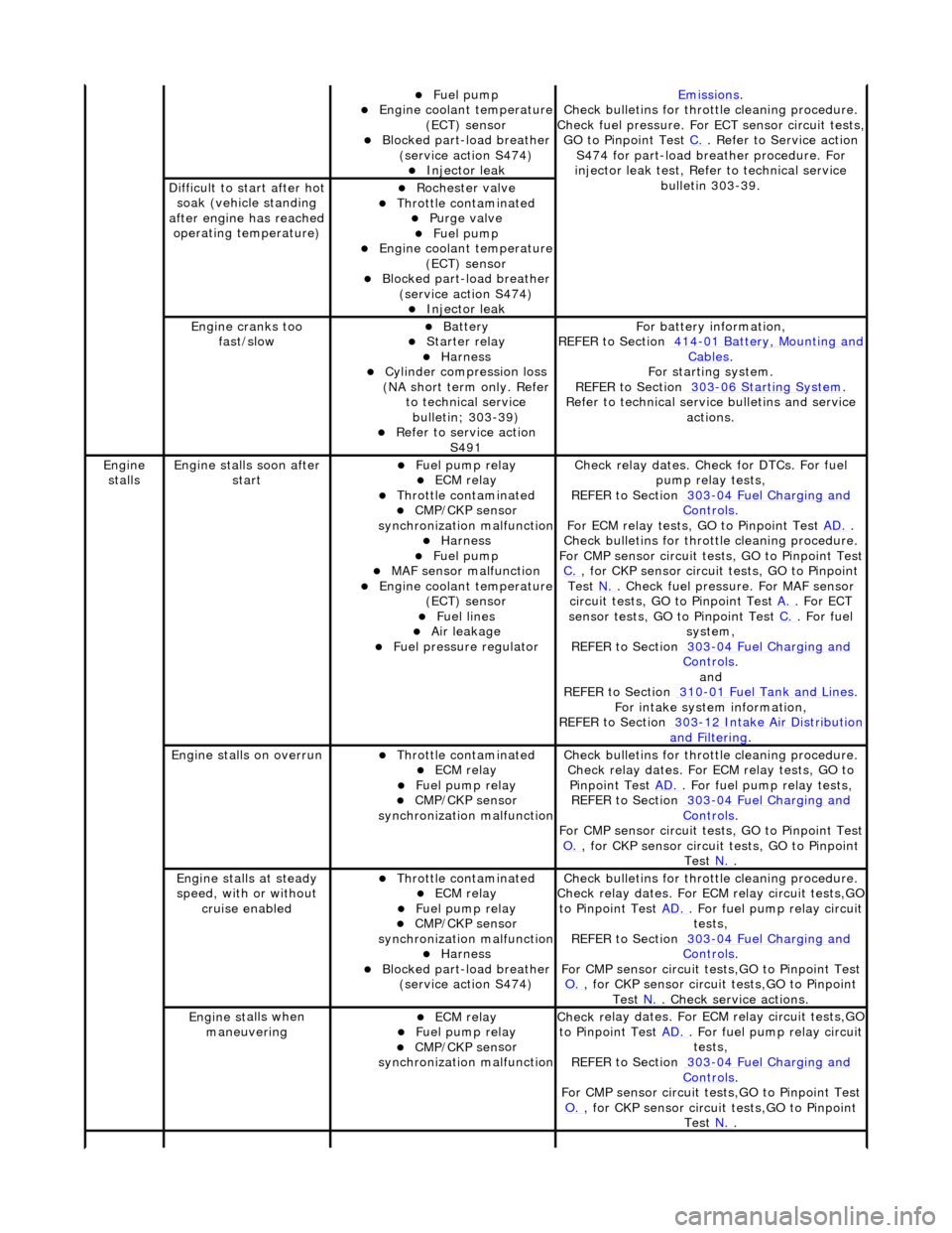
Engine
stalls
Engine st
alls soon after
start
F
uel pump relay
ECM relay Thr
ottle contaminated
CMP/CKP sen
sor
synchronization malfunction
Harness Fue
l pump
MAF
sensor malfunction
Engine coolan
t temperature
(ECT) sensor
Fue
l lines
Air leakage
F
uel pressure regulator
Check r
elay dates. Chec
k for DTCs. For fuel
pump relay tests,
REFER to Section 303
-0
4 Fuel Charging and
Controls.
F
or ECM relay tests, GO to Pinpoint Test
AD.
.
Check bull
etins for throttle cleaning procedure.
For CMP sensor circuit test s, GO to Pinpoint Test
C.
, for
CKP sensor circuit tests, GO to Pinpoint
Test N.
. Check fuel
pressure. For MAF sensor
circuit tests, GO to Pinpoint Test A.
. For EC
T
sensor tests, GO to Pinpoint Test C.
. F
or fuel
system,
REFER to Section 303
-0
4 Fuel Charging and
Controls.
and
REF
ER to Section 310
-0
1 Fuel Tank and Lines
. F
or intake system information,
REFER to Section 303
-1
2 Intake Air Distribution
and F
iltering
.
Engine
stalls on overrun
Thr
ottle contaminated
ECM relay F
uel pump relay
CMP/CKP sen
sor
synchronization malfunction
Check bull
etins for throttle cleaning procedure.
Check relay dates. For ECM relay tests, GO to Pinpoint Test AD.
. F
or fuel pump relay tests,
REFER to Section 303
-0
4 Fuel Charging and
Controls.
F
or CMP sensor circuit test
s, GO to Pinpoint Test
O.
, for
CKP sensor circuit tests, GO to Pinpoint
Test N.
.
E
ngine stalls at steady
speed, with or without cruise enabled
Thr
ottle contaminated
ECM relay F
uel pump relay
CMP/CKP sen
sor
synchronization malfunction
Harness Blocked part-load breather
(
service action S474)
Check bull
etins for throttle cleaning procedure.
Check relay dates. For EC M relay circuit tests,GO
to Pinpoint Test AD.
. F
or fuel pump relay circuit
tests,
REFER to Section 303
-0
4 Fuel Charging and
Controls.
F
or CMP sensor circuit test
s,GO to Pinpoint Test
O.
, for
CKP sensor circuit tests,GO to Pinpoint
Test N.
. Che
ck service actions.
Engine st
alls when
maneuvering
ECM relay F
uel pump relay
CMP/CKP sen
sor
synchronization malfunction
Check r
elay dates. For EC
M relay circuit tests,GO
to Pinpoint Test AD.
. F
or fuel pump relay circuit
tests,
REFER to Section 303
-0
4 Fuel Charging and
Controls.
F
or CMP sensor circuit test
s,GO to Pinpoint Test
O.
, for
CKP sensor circuit tests,GO to Pinpoint
Test N.
.
Page 1192 of 2490
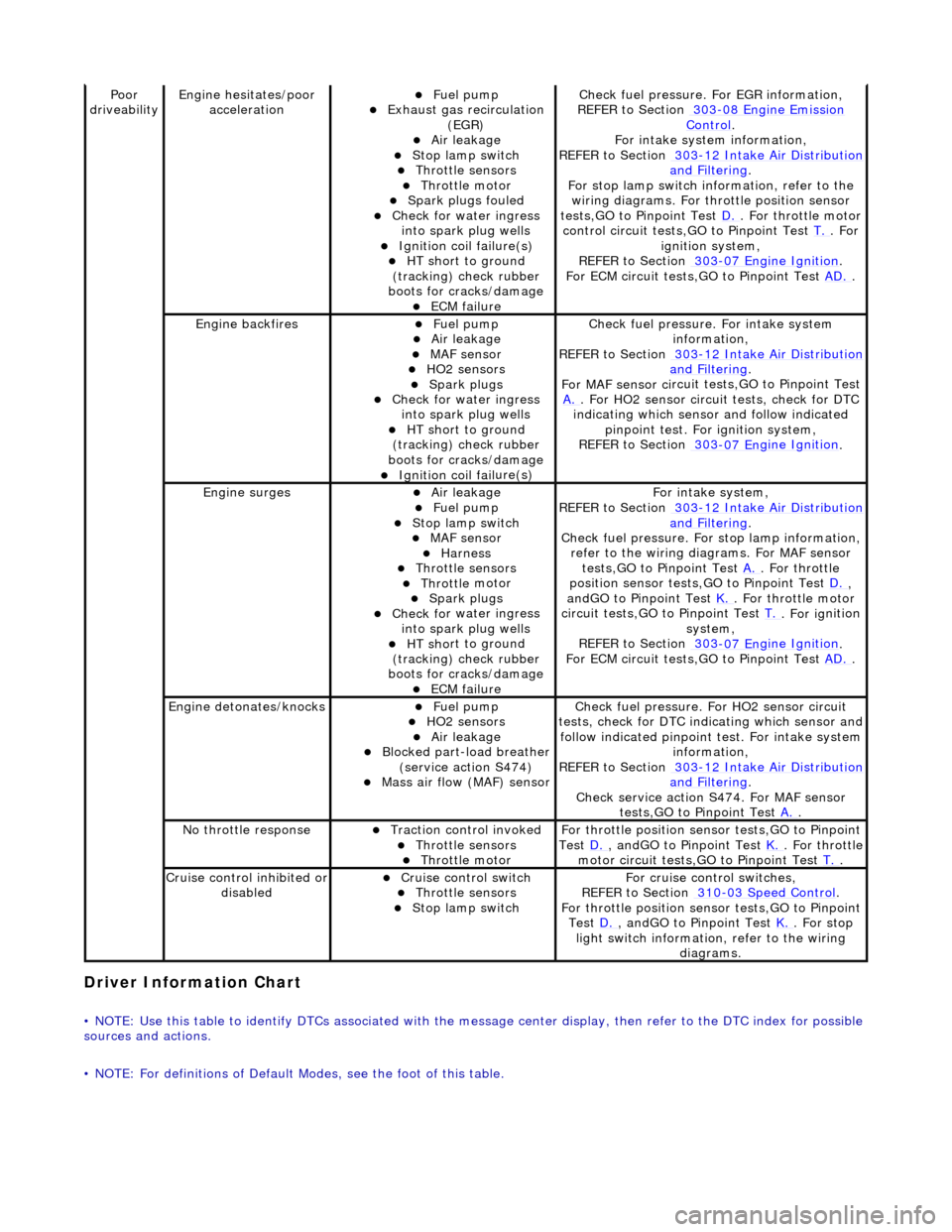
Driver Information
Chart
•
NOTE: Use this table to identify DTCs associated with the me
ssage center display, then refer to the DTC index for possible
sources and actions.
• NOTE: For definitions of Default Modes, see the foot of this table.
Poor
dr iveabilityEngine h e
sitates/poor
acceleration
Fue l
pump
Exhaus
t gas
recirculation
(EGR)
Air leakage Stop lamp swi t
ch
Throttl
e
sensors
Throttl
e
motor
Spark
plugs
fouled
Check f
o
r water ingress
into spark plug wells
Ignition coil fail
ure(s)
HT sh
o
rt to ground
(tracking) check rubber
boots for cracks/damage
ECM failu r
e
Check f
u
el pressure. For EGR information,
REFER to Section 303
-08 En gin
e Emission
Control.
F or i
ntake system information,
REFER to Section 303
-1 2
Intake Air Distribution
and F
ilt
ering
.
F or stop l
amp switch in
formation, refer to the
wiring diagrams. For throttle position sensor
tests,GO to Pinpoint Test D.
. Fo
r throttle motor
control circuit tests,GO to Pinpoint Test T.
. For
igni t
ion system,
REFER to Section 303
-07 En
gine Ignition
.
F or ECM
circuit tests,GO to Pinpoint Test
AD.
.
Engine backfiresFuel
pump
Air leakage MAF se
nsor
HO2 sensors
Spark plugs Check fo
r water ingress
into spark plug wells
HT sh o
rt to ground
(tracking) check rubber
boots for cracks/damage
Ignition coil fail
ure(s)
Chec
k fu
el pressure. For intake system
information,
REFER to Section 303
-12
Intake Air Distribution
and Filt
ering
.
F or MAF sensor ci
rcuit test
s,GO to Pinpoint Test
A.
. F or HO2 sensor
circui
t tests, check for DTC
indicating which sensor and follow indicated pinpoint test. For ignition system,
REFER to Section 303
-07 En
gine Ignition
.
Engine
s
urges
Air leakage
Fuel
pump
Stop lamp swit
ch
MAF s
e
nsor
Harness Throttl
e
sensors
Throttl
e
motor
Spark plugs
Check fo
r water ingress
into spark plug wells
HT sh o
rt to ground
(tracking) check rubber
boots for cracks/damage
ECM failu r
e
Fo
r
intake system,
REFER to Section 303
-1 2
Intake Air Distribution
and Filt
ering
.
Check fu
el pressure. For
stop lamp information,
refer to the wiring diagrams. For MAF sensor tests,GO to Pinpoint Test A.
. Fo
r throttle
position sensor tests,GO to Pinpoint Test D.
,
a n
dGO to Pinpoint Test
K.
. Fo
r throttle motor
circuit tests,GO to Pinpoint Test T.
. For ig
nition
system,
REFER to Section 303
-07 En
gine Ignition
.
F or ECM
circuit tests,GO to Pinpoint Test
AD.
.
Engine detonates/k
nocks
Fue
l
pump
HO2 sensors
Air leakage Blocked part-load breather
(s
ervice action S474)
Mass ai
r fl
ow (MAF) sensor
Chec
k fu
el pressure. Fo
r HO2 sensor circuit
tests, check for DTC indicating which sensor and
follow indicated pinpoint test. For intake system
information,
REFER to Section 303
-1 2
Intake Air Distribution
and Filt
ering
.
Check service action S474
. For MAF sensor
tests,GO to Pinpoint Test A.
.
No t
hrottle response
Traction contr
o
l invoked
Throttl
e
sensors
Throttl
e
motor
Fo
r th
rottle position sensor tests,GO to Pinpoint
Test D.
, andG O to Pinpoint
Test
K.
. Fo
r throttle
motor circuit tests,GO to Pinpoint Test T.
.
Cru i
se control inhibited or
disabled
Cru i
se control switch
Throttle
sensors
Stop lamp swit
ch
For cru
i
se control switches,
REFER to Section 310
-03
Speed Control
.
For th
rottle position sensor tests,GO to Pinpoint
Test D.
, andG O to Pinpoint
Test
K.
. For s t
op
light switch information, refer to the wiring diagrams.
Page 1199 of 2490
cyl 8
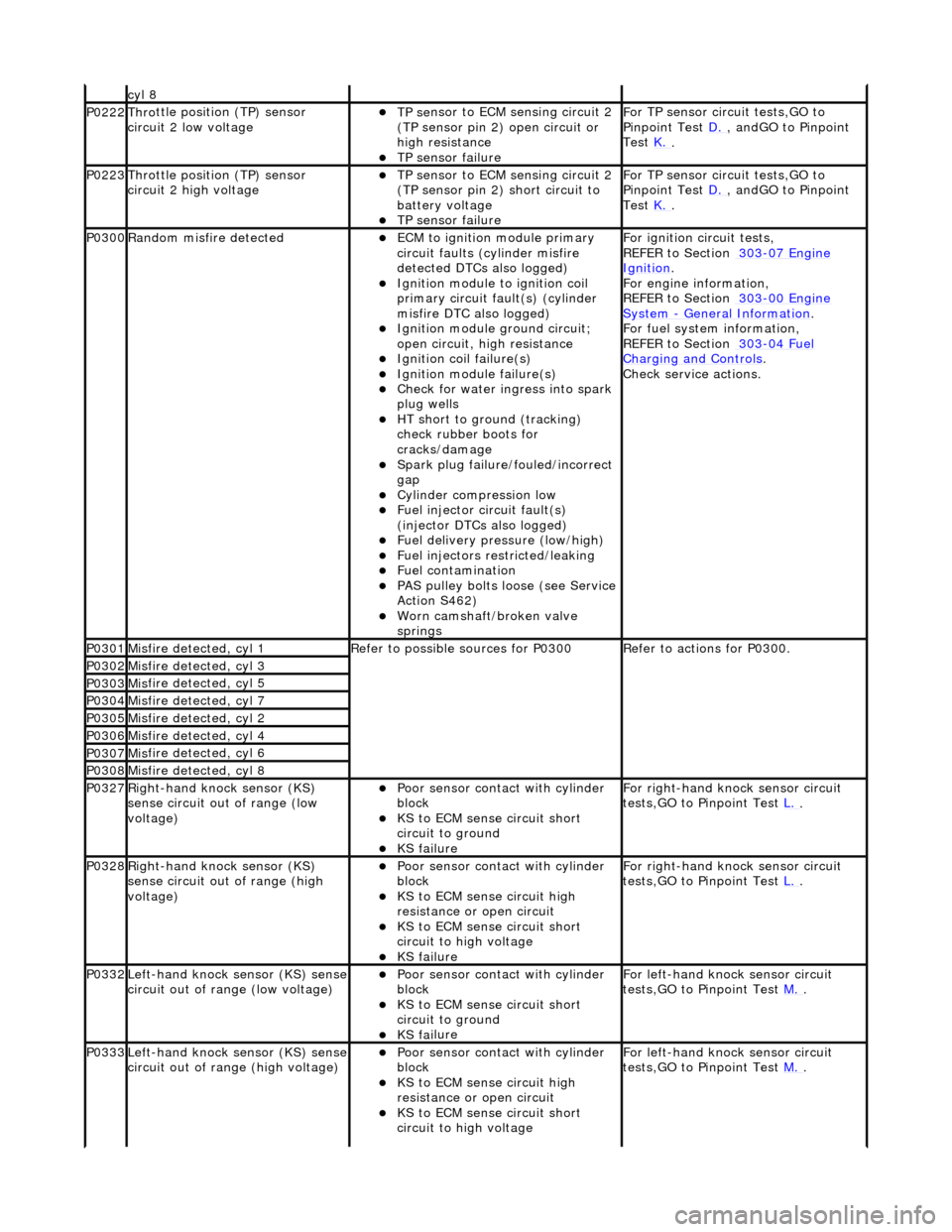
P0222Thro
ttle position (TP) sensor
circuit 2 low voltage
TP se
nsor to ECM sensing circuit 2
(TP sensor pin 2) open circuit or
high resistance
TP sensor
failure
F
or TP sensor circ
uit tests,GO to
Pinpoint Test D.
, andG
O to Pinpoint
Test K.
.
P0223Thro
ttle position (TP) sensor
circuit 2 high voltage
TP se
nsor to ECM sensing circuit 2
(TP sensor pin 2) short circuit to
battery voltage
TP sensor
failure
F
or TP sensor circ
uit tests,GO to
Pinpoint Test D.
, andG
O to Pinpoint
Test K.
.
P0300Ran
dom misfire detected
ECM to
ignition module primary
circuit faults (cylinder misfire
detected DTCs also logged)
Igni
tion module to ignition coil
primary circuit fault(s) (cylinder
misfire DTC also logged)
Ignition modu
le ground circuit;
open circuit, hi gh resistance
Ignition coil
failure(s)
Ignition modul
e failure(s)
Check f
or water ingress into spark
plug wells
HT sho
rt to ground (tracking)
check rubber boots for
cracks/damage
Spark plug
failure/fouled/incorrect
gap
Cy
linder compression low
F
uel injector circuit fault(s)
(injector DTCs also logged)
F
uel delivery pressure (low/high)
F
uel injectors restricted/leaking
Fuel contamination
P
AS pulley bolts loose (see Service
Action S462)
W
orn camshaft/broken valve
springs
F
or ignition circuit tests,
REFER to Section 303
-07
Engine
Ignition.
F
or engine information,
REFER to Section 303
-00
Engine
Sy
stem
- General
Information
.
F
or fuel system information,
REFER to Section 303
-04
Fuel
Charging and Con
trols
.
Check service
actions.
P0301Mis
fire detected, cyl 1
R
efer to possible sources for P0300
R
efer to actions for P0300.
P0302Mis
fire detected, cyl 3
P0303Mis
fire detected, cyl 5
P0304Mis
fire detected, cyl 7
P0305Mis
fire detected, cyl 2
P0306Mis
fire detected, cyl 4
P0307Mis
fire detected, cyl 6
P0308Mis
fire detected, cyl 8
P0327Right
-hand knock sensor (KS)
sense circuit out of range (low
voltage)
Poor sensor cont
act with cylinder
block
KS to
ECM sense circuit short
circuit to ground
KS fai
lure
F
or right-hand knock sensor circuit
tests,GO to Pinpoint Test L.
.
P0328Right
-hand knock sensor (KS)
sense circuit out of range (high
voltage)
Poor sensor cont
act with cylinder
block
KS to EC
M sense circuit high
resistance or open circuit
KS to
ECM sense circuit short
circuit to high voltage
KS fai
lure
F
or right-hand knock sensor circuit
tests,GO to Pinpoint Test L.
.
P0332Left-hand knock sens
or (KS) sense
circuit out of range (low voltage)
Poor sensor cont
act with cylinder
block
KS to
ECM sense circuit short
circuit to ground
KS fai
lure
F
or left-hand knoc
k sensor circuit
tests,GO to Pinpoint Test M.
.
P0333Left-hand knock sens
or (KS) sense
circuit out of range (high voltage)
Poor sensor cont
act with cylinder
block
KS to EC
M sense circuit high
resistance or open circuit
KS to
ECM sense circuit short
circuit to high voltage
F
or left-hand knoc
k sensor circuit
tests,GO to Pinpoint Test M.
.
Page 1262 of 2490
Contains th
e hydraulic system pump.
Contains
th
e fluid temperature sensor.
The epicyclic geartrain:
Provi des fi
ve forward gears and Reverse.
Has
h
ydraulically actuated, multi-disk clutches, to select the required gear ratios.
Feature
s clutch-to-clutch operation to permit
gear shifts for uninterrupted power flow.
The electro-hydraulic control unit:
Is lo c
ated in the lower part of
the unit, within the fluid pan.
Is controlled
by the TCM (transmissio
n control module), and the manual selector valve which is cable operated.
Re
gulates the flow of fluid to the ge
artrain clutches via three solenoid-operated valv es and the manual selector
valve.
Has fi ve pressure
regulators for controll
ing fluid pressures within the system.
Is con
nected to the TCM via a 16-way connector mounted on
the left-hand side of the transmission casing. Refer to
Connector Pins Identification, Section 307-01A.
The hydraulic system pump:
Is l o
cated at the front of the transmission casing.
Is dri
v
en from the impeller hub,
pressurising the fluid whenever the engine is running.
Supplie
s fluid under pressure to the torq
ue converter, geartrain, electro-hydr aulic control unit and the lubrication
circuit.
D r
aws fluid from the fluid pa
n below the transmission casing, through a filter.
The rear extension housing:
Is bolt
ed to the rear of the transmission casing.
Provides the rear engine / transmi
ssion mo
unting point; refer to section 303-01.
Carrie
s the transmission output shaft oil seal.
Filled-for-l
i
fe Fluid System
The
transm
ission is 'filled for life' and
does not require fluid changes, except where extreme driving conditions prevail.
Routine level checking is not required and a dipstick is not pr ovided. A level / filler plug is fitted for level checking and
replenishment, following service actions; see 303-01 General Procedures.
Transmission Torque Converter
Page 1266 of 2490
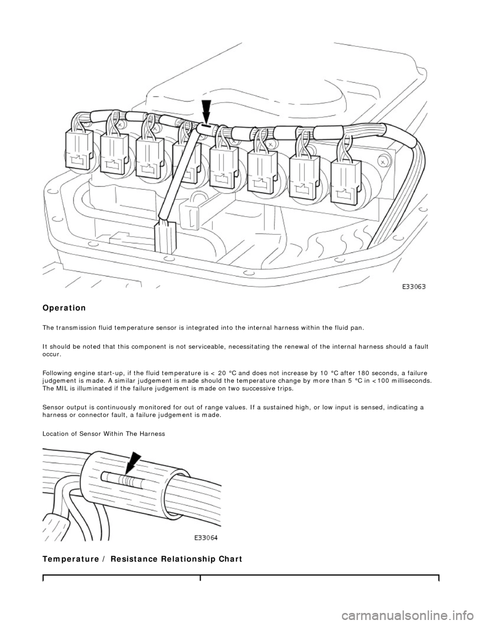
Operation
The transmission fluid temperature sensor is integrated into the internal harness within the fluid pan.
It should be noted that this component is not serviceable, ne cessitating the renewal of the internal harness should a fault
occur.
Following engine start-up, if the fluid temperature is < 20 °C and does not increase by 10 °C after 180 seconds, a failure
judgement is made. A similar judgement is made should the temperature change by more than 5 °C in <100 milliseconds.
The MIL is illuminated if the failure judgement is made on two successive trips.
Sensor output is continuously monitored for out of range values. If a sustained high, or low inpu t is sensed, indicating a
harness or connector fault, a failure judgement is made.
Location of Sensor Within The Harness
Temperature / Resistance Relationship Chart
Page 1278 of 2490
Pinpoint test A: P0741, P0742, P0743
Pinpoint test B: P0743
Connector pin(s) bent or tracking between
connections
*
DTC P1789 Ignition supply malfunction >7 < 9
voltsBattery charging system fault
Blown fuse
Harness fault
Connector loose or corroded
Connector pin(s) bent or tracking between
connections Ground fault
*
*
*
*
*
*GO to Pinpoint
Test K
*
DTC P0710 Transmission fluid temperature
sensor malfunctionDamaged sensor
Sensor out of range / short
Harness open circuit
Harness short
Connector loose or corroded
*
*
*
*
*GO to Pinpoint
Test L
*
PINPOINT TEST A : P0741, P0742, P0743
TEST CONDITIONSDETAILS/RESULTS/ACTIONS
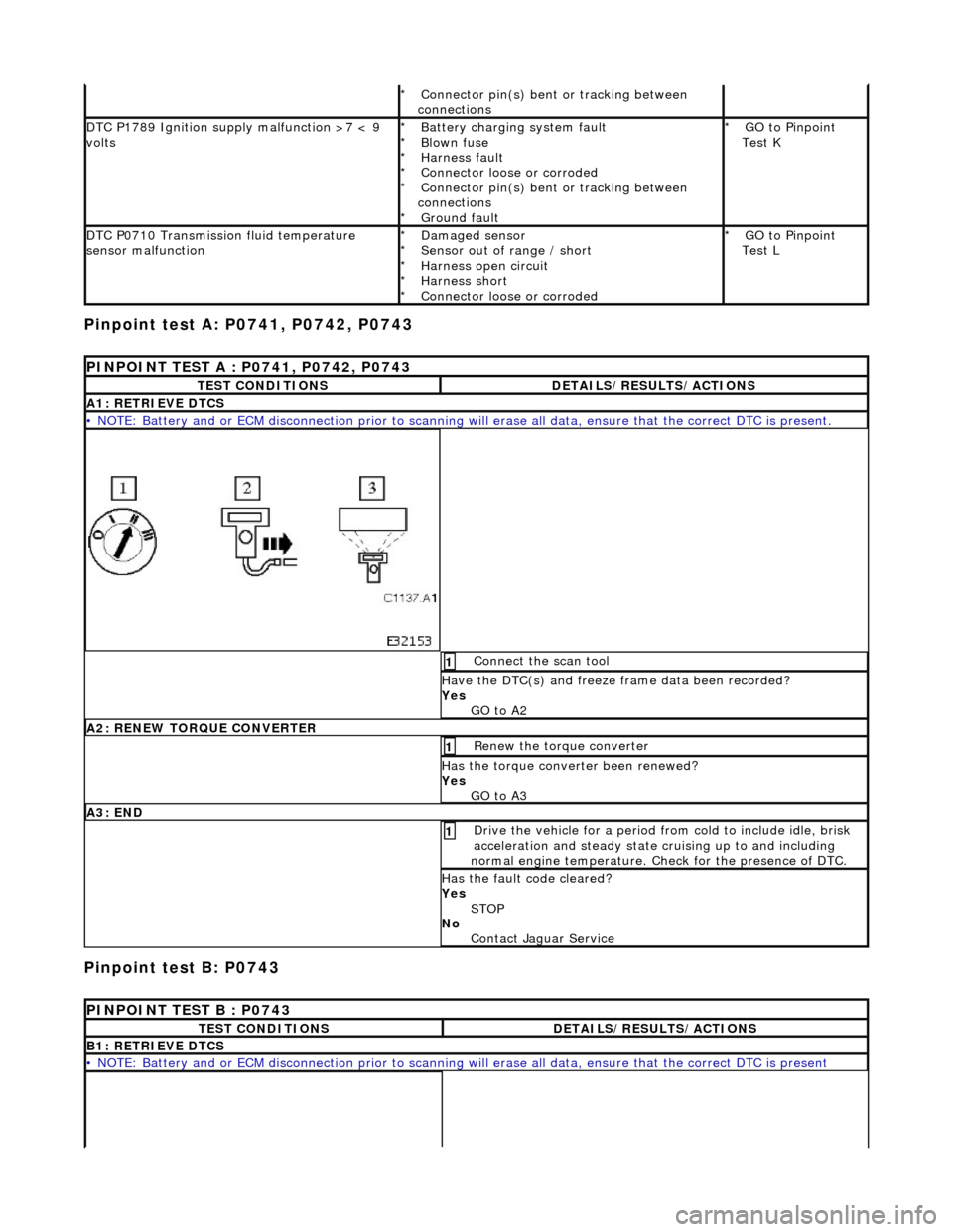
A1: RETRIEVE DTCS
• NOTE: Battery and or ECM disconnection prior to scanning wi
ll erase all data, ensure that the correct DTC is present.
Connect the scan tool 1
Have the DTC(s) and freeze frame data been recorded?
Yes GO to A2
A2: RENEW TORQUE CONVERTER
Renew the torque converter 1
Has the torque converter been renewed?
Yes GO to A3
A3: END
Drive the vehicle for a period from cold to include idle, brisk
acceleration and steady state cruising up to and including
normal engine temperature. Check for the presence of DTC. 1
Has the fault code cleared?
Yes STOP
No Contact Jaguar Service
PINPOINT TEST B : P0743
TEST CONDITIONSDETAILS/RESULTS/ACTIONS
B1: RETRIEVE DTCS
• NOTE: Battery and or ECM disconnection prior to scanning wi ll erase all data, ensure that the correct DTC is present
Page 1284 of 2490
Pinpoint test C: P0702, P0753, P0758, P0763
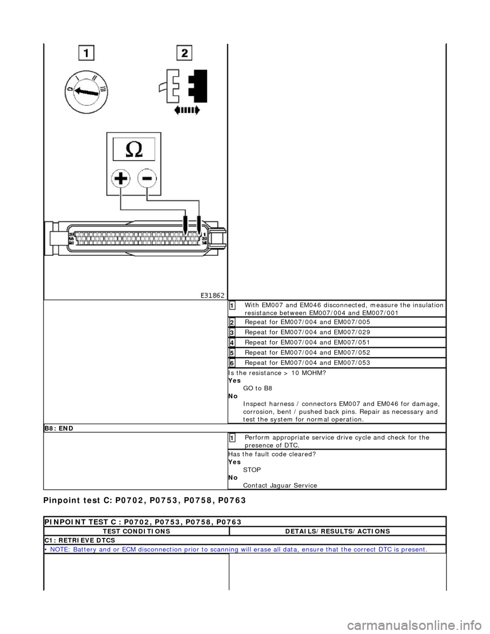
With EM007 and EM046 disconnected, measure the insulation
resistance between EM007/004 and EM007/001 1
Repeat for EM007/004 and EM007/005 2
Repeat for EM007/004 and EM007/029 3
Repeat for EM007/004 and EM007/051 4
Repeat for EM007/004 and EM007/052 5
Repeat for EM007/004 and EM007/053 6
Is the resistance > 10 MOHM?
Yes
GO to B8
No Inspect harness / connectors EM007 and EM046 for damage,
corrosion, bent / pushed back pins. Repair as necessary and
test the system for normal operation.
B8: END
Perform appropriate service drive cycle and check for the
presence of DTC. 1
Has the fault code cleared?
Yes STOP
No Contact Jaguar Service
PINPOINT TEST C : P0702, P0753, P0758, P0763
TEST CONDITIONSDETAILS/RESULTS/ACTIONS
C1: RETRIEVE DTCS
• NOTE: Battery and or ECM disconnection prior to scanning wi ll erase all data, ensure that the correct DTC is present.