Page 510 of 2490
The lower steeri ng col
umn:
Is a han
ded assembly
.
Incorporates
a col
umn to toeboard seal
which comprises a rolling element having two, low friction, PTFE rings. The
rolling element locates in a rubber b oot which seals to the toeboard.
Has a lowe
r universal joint connecting the
lower column to the steering rack.
Has an upper un
iversal joint connecting
the lower column to the upper column.
Has a NVH damper in
corporated into
the upper universal joint assembly.
May be installed in an
y orientation on the universal joint splines.
R
e
quires no setting or adjustment.
Has no s
e
rviceable components.
It is essential to disconnect the lower column from the steer ing rack before removing the engine or front suspension
crossbeam.
It e
m
Par
t
Number
De
scr
iption
1-Boot
2-Uni
v
ersal joint to upper column
3-Lower steeri
ng col
umn shaft
4-R
e
taining bolts
5-Uni
v
ersal joint to steering rack
Lower Steering Column
Page 511 of 2490
Steering Column - Steering Colu
mn Lower Shaft
Re
moval and Installation
Remov
al
1.
Raise
and support the vehicle.
For additional informat ion, refer to Section 100
-0
2 Jacking and
Liftin
g
.
2. De
tach the steering
column lower shaft.
1. Loosen the steering column lower shaft sliding joint retaining bolt.
2. Remove and discard the st eering column lower shaft
retaining bolt.
3. Detach the steering column lower shaft.
3. Lower the vehicle.
4. Remove an
d discard the steering
column lower shaft retaining
bolt.
5. De
tach the steering
column lower shaft.
6. Remove the steering column lower shaft.
De
tach the boot.
Page 512 of 2490
In
stallation
1.
CAUTIO
N: Make sure the boot
is fully seated at the top
and bottom.
Attach the boot.
2. CAUTI O
NS:
Make sure the steering column lower shaft rolling element
is fully seated into the boot.
Make sure the boot is fully seated at the top and bottom.
Install the steering column lower shaft.
3. CAUTI O
NS:
Make sure the steering column lower shaft is fully installed
to the steering column shaft splines.
Make sure the steering column lower shaft rolling element
is fully seated into the boot.
Attach the steering column lower shaft.
4. WARNING: In stall a new stee ring column lower shaft
r
etaining bolt. Failure to follow this instruction, may result in
personal injury.
Page 513 of 2490
CAUTI
ON: Make sure the steering
column lower shaft is fully
installed on the steering column shaft splines.
Install the steering column lower shaft retaining bolt.
Ti
ghten to 28 - 34 Nm.
5.
R
aise the vehicle.
6. WARNING: In
stall a new stee
ring column lower shaft
retaining bolt. Failure to follow this instruction, may result in
personal injury.
Attach the steering column lower shaft. 1. Attach the steering column lower shaft.
2. Install the steering column lower shaft retaining bolt.
1. Tighten to 28 - 34 Nm
.
3
. Tighten to 28 - 34 Nm.
Page 514 of 2490
Steering Column Switches -
Torques
Comp
onent
Nm
Swit
ch
gear securing screws
4 -
5
Steeri ng column upper and
l
ower cowl securing screws
1.
5 (
nominal)
Page 515 of 2490
Steering Column Switches - Steering Column Switches
Description an
d Operation
Ig
nition Switch
The k
ey-operated ignition switch is located on the right-hand side of the steering colu
mn and has four positions.
Position 'O'
OFF. The only position in which the key can be inserted or re moved. With the key removed, the steering lock engages. The
key can only be removed when the tran smission is in the Park position.
Position 'I'
AUXILIARY. Certain circuits , i.e. radio and windows, can be operat ed without switching on the ignition.
Position 'II'
Page 516 of 2490

IGNITION.
All circuits, except the star
ter motor, are activated. The key rema ins in this position when driving.
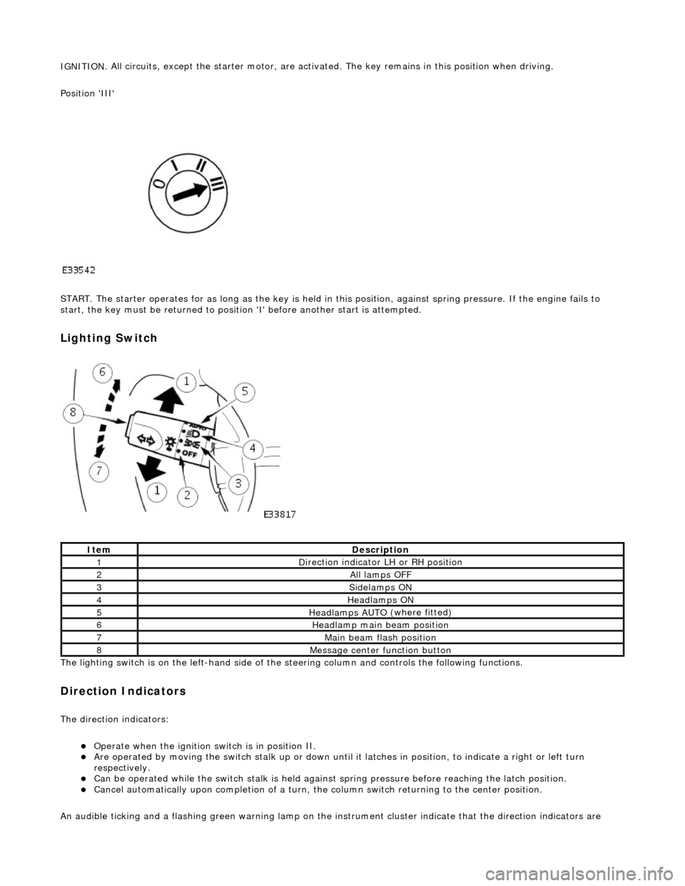
Position 'III'
START. The starter operates for as long as the key is held in this position, ag ainst spring pressure. If the engine fails to
start, the key must be returned to position 'I' befo re another start is attempted.
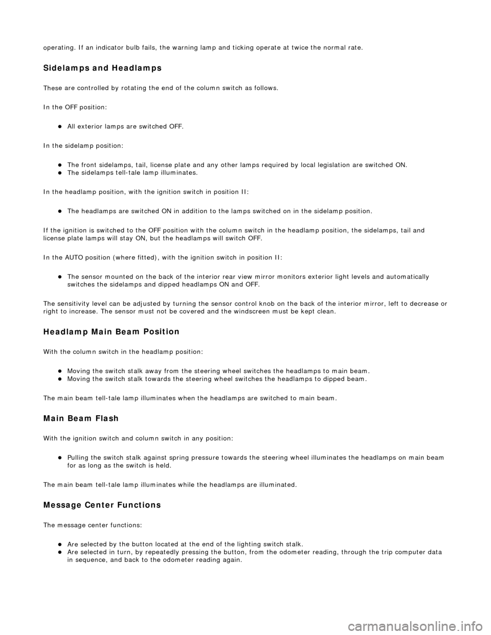
Lighting Switch
The li
ghting switch is on the left-h
and side of the steering column and controls the following functions.
Direction Indicators
The direction in
dicators:
Operate
when the ignition switch is in position II.
Are operat
ed by movi
ng the switch stalk up or down until it latches in position, to in
dicate a right or left turn
respectively.
Can be o p
erated while the switch stalk is held against
spring pressure before reaching the latch position.
Cancel
automatically upon completion of a turn, the
column switch returning to the center position.
An audible ticking and a flashing green warning lamp on the in strument cluster indicate that the direction indicators are
Ite
m
De
scr
iption
1D
i
rection indicator LH or RH position
2All lamps OFF
3Side
lamps ON
4Headlamps ON
5Headlamps AUT O
(where fitted)
6He
adlam
p main beam position
7Mai
n
beam flash position
8M
e
ssage center function button
Page 517 of 2490

o
perating. If an indicator bulb fails, the warning
lamp and ticking operate at twice the normal rate.
Sidelam
ps and Headlamps
Thes
e are controlled by rotating the end of the column switch as follows.
In the OFF position:
All
exterior lamps are switched OFF.
In the sidelamp position:
The front
sidelamps, tail, license plate and any other la
mps required by local legislation are switched ON.
The
sidelamps tell-tale lamp illuminates.
In the headlamp position, with the ignition switch in position II:
The h
eadlamps are switched ON in addition to the lamps switched on in the sidelamp position.
If the ignition is switched to the OFF position with the column switch in the headlamp position, the sidelamps, tail and
license plate lamps will stay ON, but the headlamps will switch OFF.
In the AUTO position (where fitted), with the ignition switch in position II:
Th
e sensor mounted on the back of the interior rear view
mirror monitors exterior light levels and automatically
switches the sidelamps and di pped headlamps ON and OFF.
The sensitivity level can be adjusted by turn ing the sensor control knob on the back of the interior mirror, left to decrease or
right to increase. The sensor must not be covered and the windscreen must be kept clean.
Headlamp Main Bea
m Position
Wi
th the column switch in
the headlamp position:
Movin
g the switch stalk away fro
m the steering wheel switches the headlamps to main beam.
Movin
g the switch stalk towards the steering wheel switches the headlamps to dipped beam.
The main beam tell-tale lamp illuminates when the headlamps are switched to main beam.
Ma
in Beam Flash
Wi
th the ignition switch and column switch in any position:
Pulling the
switch stalk agains
t spring pressure towards th e steering wheel illuminates the headlamps on main beam
for as long as the switch is held.
The main beam tell-tale lamp illuminates while the headlamps are illuminated.
M
essage Center Functions
T
he message center functions:
Are se
lected by the button located at the end of the lighting switch stalk.
Are se
lected in turn, by repeatedly pressing the button,
from the odometer reading, through the trip computer data
in sequence, and back to th e odometer reading again.