Page 483 of 2490

P
arts List
The positive center-feel torsion bar improves the straight ahead feel of the steering in the region where very small amounts
of hydraulic pressure, and hence re action pressure, are generated.
The torsion bar assembly forms part of the hydraulic control valve assembly , and includes an axially pre-loaded metal
bellows spring, which is arranged co-axially with the torsion bar. The torsion bar is positively connected between the end
piece and the input shaft. One end of the bellows spring is attached to the input shaft, while the other end is attached to a
centering device. The centering device has two prism-shaped recesses with ca ged, guided, ball bearings arranged between
the recesses, and determines the zero-torsion position of the bellows spring.
On turning the steering wheel from the straight ahead position, the spring fo rces of the torsion bar assembly must be
overcome. Initially, the bellows spring produces substantial additional torsional resistance. However, after an angular
movement of approximately 0.2 degrees the torsional rigidity decreases and becomes similar to a conventional torsion bar.
It
em
Par
t Number
De
scription
1—End piece
2—Torsio
n bar
3—Caged ball bearing
s
4—Centering device
5—Bel
lows spring
6—In
put shaft
Positive Center-Feel Torsion Bar
Torsio
n Bar Components
Page 484 of 2490
P a
rts List
The power assisted steering pump:
Is mo u
nted on a bracket installe
d on the front of the engine.
Provides hydraul
ic pressure fo
r the power steering system.
Is of the roll
er vane type.
Is belt driven from th
e en
gine crankshaft.
Will provide 1
05 bar f
luid pressure.
The pump is not serviceable and should be renewed as a complete assembly.
Fluid Reservoir
Re
servoir and Hoses
Ite
m
Par
t
Number
De
scr
iption
1—Power as
si
sted steering pump
2—Engine
m
ounting bracket
3—High
pressure port
Power Assisted Steering Pump
Page 485 of 2490

The fluid reservo
ir:
Is lo
cated in the engine compartment, mounted on the engine compartment fuse box bracket.
Incorporates
a 10 micron, li
fetime, integral filter.
Has a cap
acity of 0.4 liter.
Has a dipsti
ck incorporated into the filler cap for checking the fluid level.
A new reservoir must be fitted if the steering rack, pump or fluid cooler are renewed.
Fluid C
ooler
P
arts List
The fluid cooler:
Is
resiliently mounted on th
e front body cross member.
Coo
ls the fluid before it is
returned to the reservoir.
Is
of the wire-bound tube type.
Has i
ntegral hoses.
Supply and Return Hoses a
nd Pipework
The supply and return h
oses and
pipework deliver fluid at high pressure from the pump to th e steering rack assembly. The
fluid is then returned to th e reservoir through the cooler tube. The high pressure supply hose contains two cable-type
attenuators, one at each end, to reduce nois e. The return pipe is clipped to the steering rack housing by a resilient
mounting.
It
em
Par
t Number
De
scription
1—Fl
uid reservoir
2—Supply line
3—R
eturn line
4—Fi
ller cap
It
em
Par
t Number
De
scription
1—Front body cross member
2—F
luid cooler
3—Inte
gral hoses
4—Cooler m
ounting
P
arts List
Page 487 of 2490

m
ember. The quick-fit connector O-rings are not serviceable.
Special tool JD 182 is required to disconnect the quick-fit connector.
Hydraulic System
P
arts List
Hydraulic System
Op
erating Principle
The rot
ary motion of the steering wheel is converted, via the st
eering rack pinion, to the lateral motion of the rack. Steering
assistance is provided by pressurized fluid being directed against a piston operating within the rack cylinder. Rack
movement is achieved by diffe rential pressures being applied on either si de of the rack piston, caused by unequal
restrictions within the hydraulic control valve.
The main components of the hydraulic control valve are the rota ry distributor, control sleeve and hydraulic reaction piston.
It
em
Par
t Number
De
scription
1—F
luid reservoir
2—Pum
p
3—Pressure and fl
ow limiting valve
4—Supply line
5—R
eturn line
6—Steeri
ng rack
7—Pin
ion
8—O
perating cylinder and piston
9—Hydrau
lic control valve
10—Hydraulic reaction
piston
11—Control
sleeve
12—R
otary distributor
13—F
luid cooler
A
quick-fit connector with double O-ring se
als is incorporated in the return line and is clipped to the right-hand chassis side
Page 488 of 2490

The rotary distri
butor and control sleeve turn relative to ea
ch other, forming the unequal restrictions which create the
differential pressures to operat e the rack piston; the displacement of the di stributor and sleeve being controlled by the
elastic deformation of a torsion bar which is concentric with the pinion and valve. Refer to Positive Center-Feel Torsion Bar
in this sub-sectio n.
The hydraulic reaction piston moves axially, relative to th e rotary distributor, and is connected to the control sleeve by a
three-bearing helical screw. Pressure applied either side of the hydraulic reaction piston is translated into a rotational force
which increases steering effort. For detail s of Servotronic speed-sensitive steering control, refer to Servotronic Control in
this sub-section.
When the vehicle is travelling straight ah ead, the valve restrictions are balanced, thus providing equal pressures on either
side of the rack piston. When load is a pplied at the steering wheel, the two halves of the control valve (rotary distributor
and control sleeve) are displaced making the restrictions unequa l. The resulting differential pressures on either side of the
rack piston, assist the steering rack to mo ve to left or right. As the turning load is removed, the pressures equalize again
and the steering return s to the straight ahead position , aided by suspension geometry.
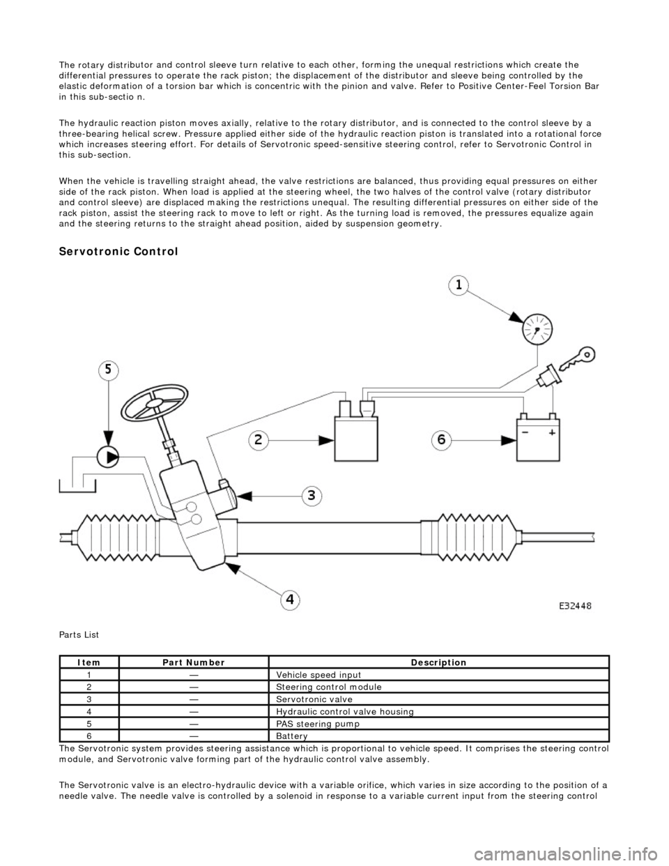
Serv
otronic Control
P a
rts List
The Servotronic system provides steering assistance which is pr oportional to vehicle speed. It comprises the steering control
module, and Servotronic valve forming part of the hydraulic control valve assembly.
The Servotronic valve is an electro-hydrauli c device with a variable orifice, which varies in size according to the position of a
needle valve. The needle valve is controlled by a solenoid in response to a variable current input from the steering control
Ite
m
Part
Number
Descr
iption
1—Vehi
cl
e speed input
2—Steeri
ng control
module
3—Servotronic valve
4—Hydraulic
control valve housing
5—PAS stee
rin
g pump
6—Batt
ery
Page 489 of 2490

modul
e. This regulates the fluid flow
through the hydraulic control valve, wh ich determines the amount of steering
assistance.
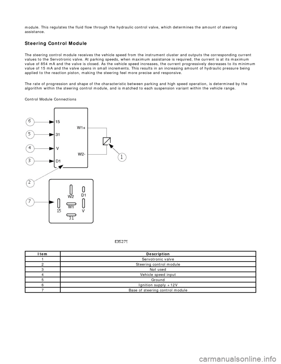
Steering Control Module
The steering control
module re
ceives the vehicle speed from the instrument cluster and outputs the corresponding current
values to the Servot ronic valve. At parking speeds, wh en maximum assistance is required , the current is at its maximum
value of 854 mA and the valve is closed. As the vehicle speed increases, the current progressively decreases to its minimum
value of 15 mA and the valve opens in sma ll increments. This results in an increasing amount of hydraulic pressure being
applied to the reaction piston, making the steering feel more precise and responsive.
The rate of progression and shape of the characteristic between parking and high speed operation, is determined by the
algorithm within the steering control module, and is matched to each suspension variant within the vehicle range.
Control Module Connections
It
em
De
scription
1Servotronic valve
2Steeri
ng control module
3No
t used
4Vehi
cle speed input
5Ground
6Ignition su
pply +12V
7Base of
steering control module
Page 490 of 2490

Power Steering - Power Steering
Diagn
osis and Testing
Refer to the Description and Operation sub-section for details of the power operated steering system and Servotronic control
system.
Power Steer ing Pressure Test
Test Equ
i
pment
Parts List
In
stalling Test Equipment
To
in
stall the pressure test equipment:
Pla
c
e a suitable drain tray below the PAS pump.
Install a hose clamp
on
the re
servoir to pump hose prior to disconnecting any hoses, to avoid unnecessary loss of
fluid.
Di sc
onnect the hose from the PAS pump high pres
sure outlet.
Ins
tall the pump outlet to hose ad
aptor. Do not omit the O-ring.
Conn
ect the pump adaptor to control valve hose of the test equipment.
Install th
e adaptor in the high pressure hose previ
ously re
moved from the pump outlet.
Conne
ct the connector of the test equipment hose to the adaptor.
R
e
move the hose clamp fro
m the reservoir hose.
Start th
e engine.
With the control valve OPEN and the engine idling , the following system pressures may be checked:
Du
ring turning.
W
h
en the steering is
held on full lock.
With
the steeri
ng at rest.
• WARNINGS:
TO AVOID EXCESSIVE HEATING OF THE PAS PUMP, DO NOT CLOSE THE VALVE FOR LONGER THAN NECESSARY.
Ite
m
Par
t
Number
De
scr
iption
1—Pressure
gauge hose
2—Pump return hose
3—Pump return hose connector
4—Test equi
pment to
HP hose adaptor
5—Pump HP outlet to hose adaptor
6—Pump adaptor
to control valve hose
7—Control valve
Page 492 of 2490
Power Steering - Steering Gear
Remo
val and Installation
Remov
a
l
All vehicles
S
p
ecial Tool(s)
Taper Sep
a
rator
211-098 (JD 100)
1. Centralize steeri ng the wheel.
2. Raise and support the vehicle on a four-post ramp.
3. Place a suitable drain pan under the stee ring gear.
4. Fr
om below the vehicle, check that
steering gear is centralized
by aligning the centralizing notc h on the dirt protection cover
with the location hole in the pinion housing casting.
5. NOTE : R
ight-hand shown, left-hand similar.
Remove and discard bo th tie rod end nuts.
6. NOTE : R
ight-hand shown, left-hand similar.
Detach both of the tie rod ends.
1. Fit the special tool to tie rod end.
2. Tighten the tool bolt to release the taper.
Re
move the tool.