1998 JAGUAR X308 steering
[x] Cancel search: steeringPage 1747 of 2490
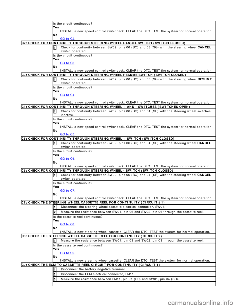
Is th
e circuit continuous?
Yes INSTALL a new speed control switchpack. CLEAR the DTC. TEST the system for normal operation.
No GO to C2
.
C2
: CHECK FOR CONTINUITY THROUGH STEERIN
G WHEEL CANCEL SWITCH (SWITCH CLOSED)
Check f
or continuity between SW02, pins 06
(BO) and 03 (SG) with the steering wheel CANCEL
switch operated.
1
Is th
e circuit continuous?
Yes GO to C3
.
No
INSTALL a new speed control switchpack. CLEAR the DTC. TEST the system for normal operation.
C3
: CHECK FOR CONTINUITY THROUGH STEERIN
G WHEEL RESUME SWITCH (SWITCH CLOSED)
Check f
or continuity between SW02, pins 06
(BO) and 03 (SG) with the steering wheel RESUME
switch operated.
1
Is th
e circuit continuous?
Yes GO to C4
.
No
INSTALL a new speed control switchpack. CLEAR the DTC. TEST the system for normal operation.
C4
: CHECK FOR CONTINUITY THROUGH STEERING
WHEEL + AND - SWITCHES (SWITCHES OPEN)
Chec
k for continuity between SW02
, pins 06 (BO) and 04 (SR) with the steering wheel switches
inactive.
1
Is th
e circuit continuous?
Yes INSTALL a new speed control switchpack. CLEAR the DTC. TEST the system for normal operation.
No GO to C5
.
C5
: CHECK FOR CONTINUITY THROUGH STEER
ING WHEEL + SWITCH (SWITCH CLOSED)
Check f
or continuity between SW02, pins 06
(BO) and 04 (SR) with the steering wheel CANCEL
switch operated.
1
Is th
e circuit continuous?
Yes GO to C6
.
No
INSTALL a new speed control switchpack. CLEAR the DTC. TEST the system for normal operation.
C6
: CHECK FOR CONTINUITY THROUGH STEER
ING WHEEL - SWITCH (SWITCH CLOSED)
Check f
or continuity between SW02, pins 06
(BO) and 04 (SR) with the steering wheel CANCEL
switch operated.
1
Is th
e circuit continuous?
Yes GO to C7
.
No
INSTALL a new speed control switchpack. CLEAR the DTC. TEST the system for normal operation.
C7: CHECK THE STEERING
WHEEL CASSETTE
REEL FOR CONTINUITY (CIRCUIT #1)
Di
sconnect the steering wheel cassette electrical connector, SW01.
1
Meas
ure the resistance between SW01, pin 06
and SW02, pin 06 through the cassette reel.
2
Is th
e cassette reel continuous?
Yes GO to C8
.
No
INSTALL a new steering wheel cassette. CLEAR the DTC. TEST the system for normal operation.
C8: CHECK THE STEERING
WHEEL CASSETTE
REEL FOR CONTINUITY (CIRCUIT 2)
Meas
ure the resistance between SW01, pin 03
and SW02, pin 03 through the cassette reel.
1
Is th
e cassette reel continuous?
Yes GO to C9
.
No
INSTALL a new steering wheel cassette. CLEAR the DTC. TEST the system for normal operation.
C9: CHECK THE ECM
TO CASSETTE REEL
CIRCUIT FOR CONTINUITY (CIRCUIT 1)
Di
sconnect the battery negative terminal.
1
D
isconnect the ECM electrical connector, EM11.
2
Meas
ure the resistance between EM11, pin 01 (SR) and SW01, pin 04 (SR).
3
Page 1748 of 2490
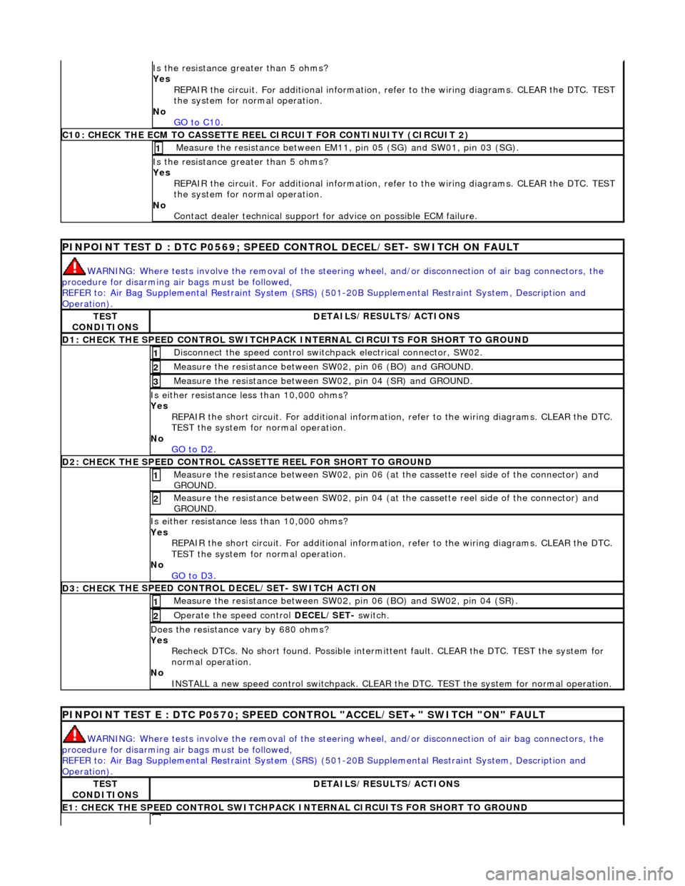
Is the res
istance greater than 5 ohms?
Yes REPAIR the circuit. For additional information, refer to the wiring diagrams. CLEAR the DTC. TEST
the system for normal operation.
No GO to C10
.
C10: CHECK T H
E ECM TO CASSETTE REEL
CIRCUIT FOR CONTINUITY (CIRCUIT 2)
Measure t
he resistance between EM11,
pin 05 (SG) and SW01, pin 03 (SG).
1
Is the res
istance greater than 5 ohms?
Yes REPAIR the circuit. For additional information, refer to the wiring diagrams. CLEAR the DTC. TEST
the system for normal operation.
No Contact dealer technical support for advice on possible ECM failure.
PI
NPOINT TEST D : DTC P0
569; SPEED CONTROL DECEL/SET- SWITCH ON FAULT
WARN
ING: Where tests involve the removal of the steering
wheel, and/or disconnection of air bag connectors, the
procedure for disarming air bags must be followed,
REFER to: Air Bag Supplemental Re straint System (SRS)
(50
1-20B Supplemental Restra
int System, Description and
Operation).
TE S
T
CONDITIONS
D E
TAILS/RESULTS/ACTIONS
D1: CHECK
THE SPEED CONTROL SWITCHPACK IN
TERNAL CIRCUITS FOR SHORT TO GROUND
Disc
onnect the speed control switch
pack electrical connector, SW02.
1
Measure t
he resistance between SW
02, pin 06 (BO) and GROUND.
2
Measure t
he resistance between SW
02, pin 04 (SR) and GROUND.
3
Is either resistance le
ss than 10,000 ohms?
Yes REPAIR the short circuit. For addi tional information, refer to the wiring diagrams. CLEAR the DTC.
TEST the system for normal operation.
No GO to D2
.
D2: CHECK
THE SPEED CONTROL CASSE
TTE REEL FOR SHORT TO GROUND
Me
asure the resistance between SW02, pin 06 (at the cassette reel side of the connector) and
GROUND.
1
M e
asure the resistance between SW02, pin 04 (at the cassette reel side of the connector) and
GROUND.
2
Is either resi stance le
ss than 10,000 ohms?
Yes REPAIR the short circuit. For addi tional information, refer to the wiring diagrams. CLEAR the DTC.
TEST the system for normal operation.
No GO to D3
.
D3: CHECK
THE SPEED CONTROL DECEL/SET- SWITCH ACTION
Meas
ure t
he resistance between SW02,
pin 06 (BO) and SW02, pin 04 (SR).
1
Operate
the speed control
DECEL/SET- switch.
2
Do
es the resistance
vary by 680 ohms?
Yes Recheck DTCs. No short found. Po ssible intermittent fault. CLEAR the DTC. TEST the system for
normal operation.
No INSTALL a new speed control switchpack. CLEAR the DTC. TEST the system for normal operation.
PINPOI
NT TEST E : DTC P0570; SPEED CONTROL "ACCEL/SET+" SWITCH "ON" FAULT
WAR
N
ING: Where tests involve the removal of the steering
wheel, and/or disconnection of air bag connectors, the
procedure for disarming air bags must be followed,
REFER to: Air Bag Supplemental Re straint System (SRS)
(50
1-20B Supplemental Restra
int System, Description and
Operation).
TE S
T
CONDITIONS
D E
TAILS/RESULTS/ACTIONS
E1
: CHECK THE SPEED CONTROL
SWITCHPACK IN
TERNAL CIRCUITS FOR SHORT TO GROUND
Page 1749 of 2490
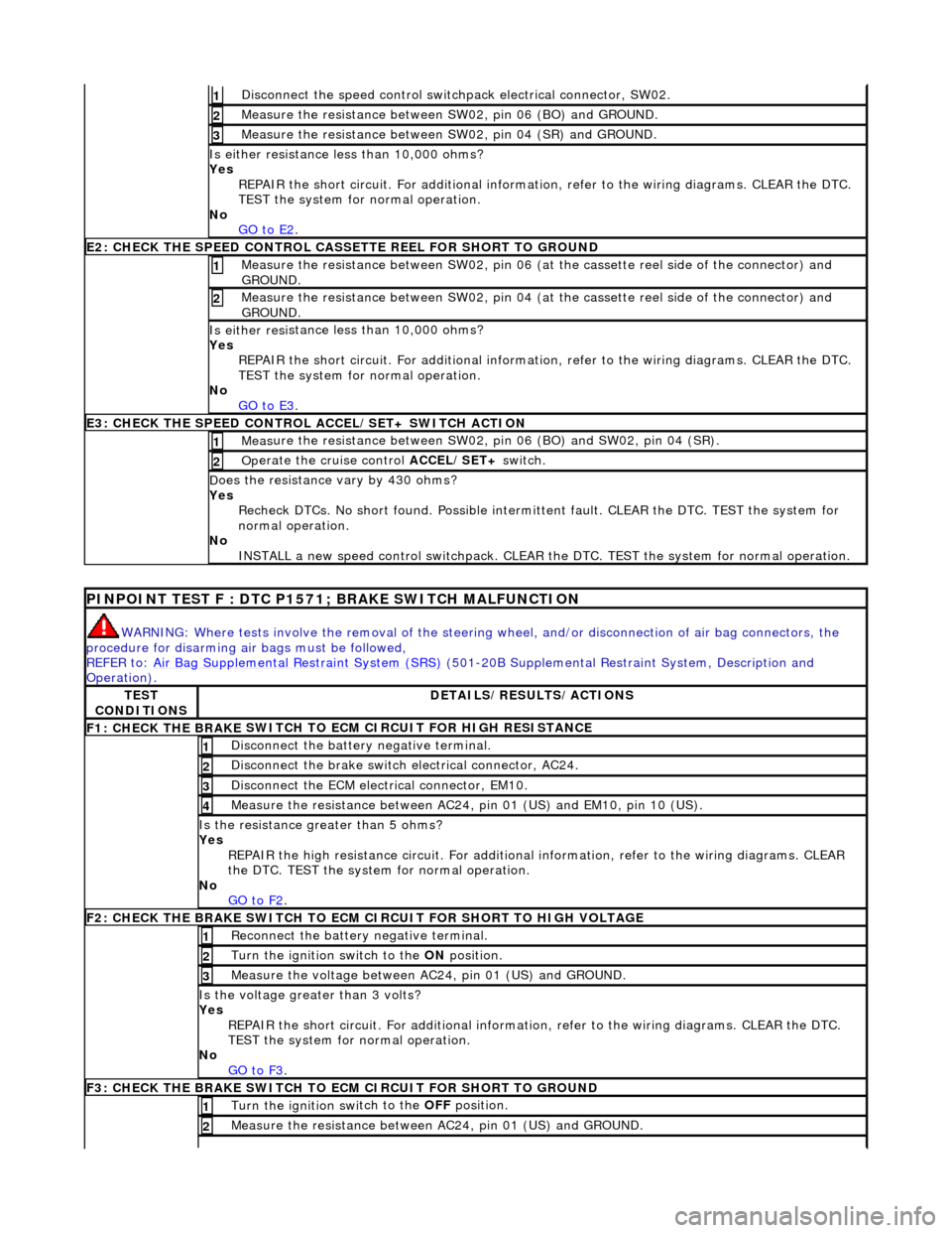
Di
sconnect the speed control switch
pack electrical connector, SW02.
1
Meas
ure the resistance between SW
02, pin 06 (BO) and GROUND.
2
Meas
ure the resistance between SW
02, pin 04 (SR) and GROUND.
3
Is either resi
stance
less than 10,000 ohms?
Yes REPAIR the short circuit. For addi tional information, refer to the wiring diagrams. CLEAR the DTC.
TEST the system for normal operation.
No GO to E2
.
E2
: CHECK THE SPEED CONTROL CASSE
TTE REEL FOR SHORT TO GROUND
M
easure the resistance between SW02, pin 06 (at the cassette reel side of the connector) and
GROUND.
1
M
easure the resistance between SW02, pin 04 (at the cassette reel side of the connector) and
GROUND.
2
Is either resi
stance
less than 10,000 ohms?
Yes REPAIR the short circuit. For addi tional information, refer to the wiring diagrams. CLEAR the DTC.
TEST the system for normal operation.
No GO to E3
.
E3
: CHECK THE SPEED CONTROL
ACCEL/SET+ SWITCH ACTION
Meas
ure the resistance between SW02,
pin 06 (BO) and SW02, pin 04 (SR).
1
Op
erate the cruise control
ACCEL/SET+ switch.
2
D
oes the resistance
vary by 430 ohms?
Yes Recheck DTCs. No short found. Po ssible intermittent fault. CLEAR the DTC. TEST the system for
normal operation.
No INSTALL a new speed control switchpack. CLEAR the DTC. TEST the system for normal operation.
P
INPOINT TEST F : DTC P1571;
BRAKE SWITCH MALFUNCTION
WAR
NING: Where tests involve the removal of the steering
wheel, and/or disconnection of air bag connectors, the
procedure for disarming air bags must be followed,
REFER to: Air Bag Supplemental Re straint System (SRS)
(501-20B Supplemental Restra
int System, Description and
Operation).
TE
ST
CONDITIONS
D
ETAILS/RESULTS/ACTIONS
F1: CHECK THE BRAKE
SWITCH TO
ECM CIRCUIT FOR HIGH RESISTANCE
Di
sconnect the battery negative terminal.
1
Di
sconnect the brake switch electrical connector, AC24.
2
D
isconnect the ECM electrical connector, EM10.
3
Meas
ure the resistance between AC24,
pin 01 (US) and EM10, pin 10 (US).
4
Is th
e resistance greater than 5 ohms?
Yes REPAIR the high resistance circui t. For additional information, refer to the wiring diagrams. CLEAR
the DTC. TEST the system for normal operation.
No GO to F2
.
F2: CHECK THE BRAKE
SWITCH TO ECM
CIRCUIT FOR SHORT TO HIGH VOLTAGE
R
econnect the battery negative terminal.
1
Turn the ignition swi
tch to the ON
position.
2
M
easure the voltage between AC24, pin 01 (US) and GROUND.
3
Is th
e voltage greater than 3 volts?
Yes REPAIR the short circuit. For addi tional information, refer to the wiring diagrams. CLEAR the DTC.
TEST the system for normal operation.
No GO to F3
.
F3: CHECK THE BRAKE
SWITCH TO
ECM CIRCUIT FOR SHORT TO GROUND
Turn the ignition swi
tch to the OFF
position.
1
Meas
ure the resistance between AC24, pin 01 (US) and GROUND.
2
Page 1778 of 2490
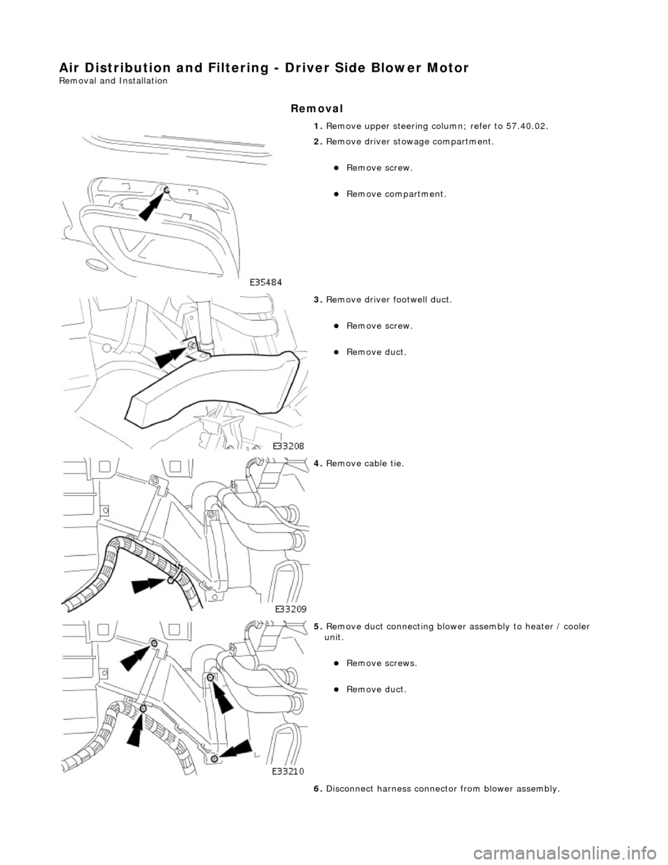
Air Distribution and Filtering - Driver Side Blower Motor
Removal and Installation
Removal
1. Remove upper steering co lumn; refer to 57.40.02.
2. Remove driver stowage compartment.
Remove screw.
Remove compartment.
3. Remove driver footwell duct.
Remove screw.
Remove duct.
4. Remove cable tie.
5. Remove duct connecting blower assembly to heater / cooler
unit.
Remove screws.
Remove duct.
6. Disconnect harness connector from blower assembly.
Page 1788 of 2490
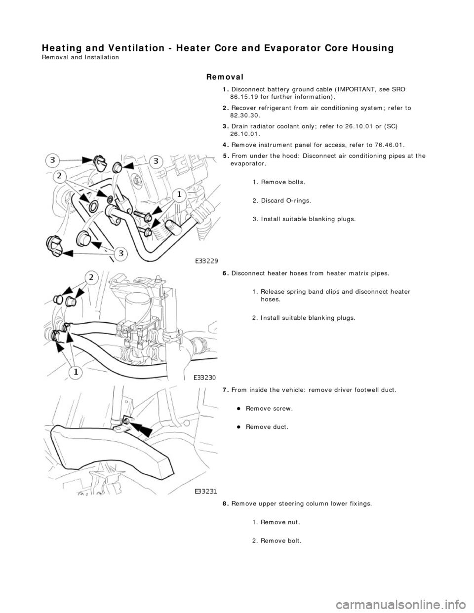
Heating and Ventilation - Heater Core and Evaporator Core Housing
Removal and Installation
Removal
1. Disconnect battery ground cable (IMPORTANT, see SRO
86.15.19 for further information).
2. Recover refrigerant from air co nditioning system; refer to
82.30.30.
3. Drain radiator coolant only; refer to 26.10.01 or (SC)
26.10.01.
4. Remove instrument panel for access, refer to 76.46.01.
5. From under the hood: Disconnect air conditioning pipes at the
evaporator.
1. Remove bolts.
2. Discard O-rings.
3. Install suitable blanking plugs.
6. Disconnect heater hoses from heater matrix pipes.
1. Release spring band clips and disconnect heater hoses.
2. Install suitable blanking plugs.
7. From inside the vehicle: re move driver footwell duct.
Remove screw.
Remove duct.
8. Remove upper steering column lower fixings.
1. Remove nut.
2. Remove bolt.
Page 1789 of 2490
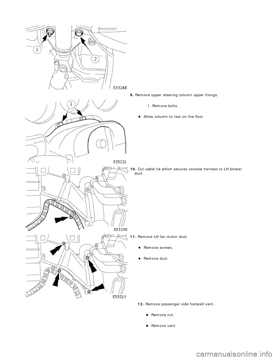
9. Remove upper steering column upper fixings.
1. Remove bolts.
Allow column to rest on the floor
10. Cut cable tie which secures console harness to LH blower
duct.
11. Remove LH fan motor duct.
Remove screws.
Remove duct.
12. Remove passenger si de footwell vent.
Remove nut.
Remove vent.
Page 1796 of 2490
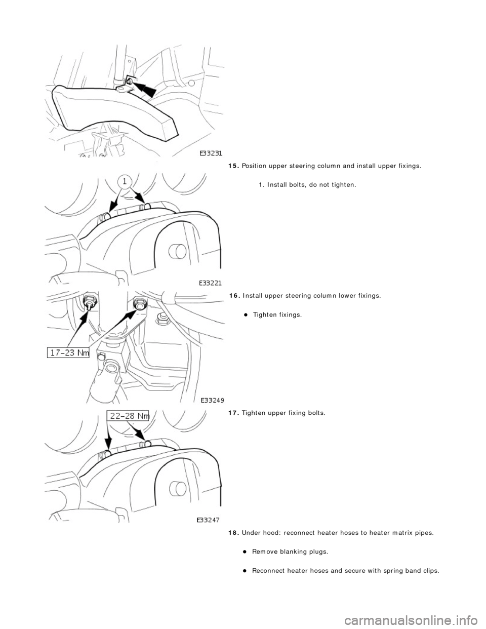
15. Position upper steering column and install upper fixings.
1. Install bolts, do not tighten.
16. Install upper steering column lower fixings.
Tighten fixings.
17. Tighten upper fi xing bolts.
18. Under hood: reconnect heater ho ses to heater matrix pipes.
Remove blanking plugs.
Reconnect heater hoses and secure with spring band clips.
Page 1804 of 2490
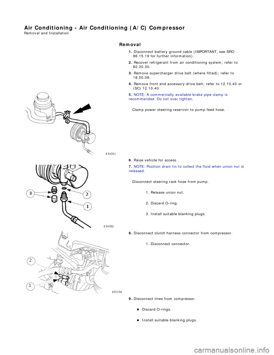
Air Conditioning - Air Conditioning (A/C) Compressor
Removal and Installation
Removal
1. Disconnect battery ground cable (IMPORTANT, see SRO
86.15.19 for further information).
2. Recover refrigerant from air co nditioning system; refer to
82.30.30.
3. Remove supercharger drive belt (where fitted); refer to
18.50.08.
4. Remove front end accessory dr ive belt; refer to 12.10.40 or
(SC) 12.10.40.
5. NOTE: A commercially availa ble brake pipe clamp is
recommended. Do not over tighten.
Clamp power steering reservoir to pump feed hose.
6. Raise vehicle for access
7. NOTE: Position drain tin to collect the fluid when union nut is
released.
Disconnect steering rack hose from pump. 1. Release union nut.
2. Discard O-ring.
3. Install suitable blanking plugs.
8. Disconnect clutch harness connector from compressor.
1. Disconnect connector.
9. Disconnect lines from compressor.
Discard O-rings.
Install suitable blanking plugs.