Page 1806 of 2490
3. Install lines to compressor.
Install new O-ring seal and lubricate with clean
compressor oil.
4. Connect clutch harness connector to compressor.
1. Connect clutch connector.
5. Connect power steering hose to pump.
1. Remove blanking plugs.
2. Install new O-ring seal and lubricate with clean
compressor oil.
3. Tighten union nut.
6. Lower ramp.
7. Unclamp power steering rese rvoir to pump feed hose.
Page 1831 of 2490

other sensors. This feature prevents the effects of sudden changes in air outlet temperatures due to factors such as:
Recirculating air from the engine cooling pack at low vehicle speeds Sudden changes in ambient temperature The effects of water splash
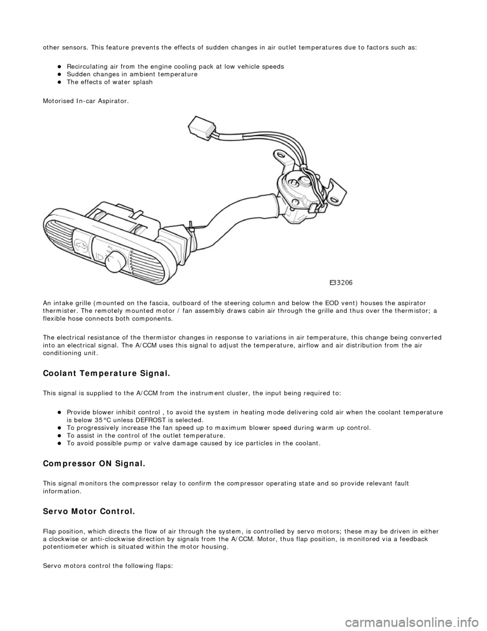
Motorised In-car Aspirator.
An intake grille (mounted on the fascia , outboard of the steering column and below the EOD vent) houses the aspirator
thermister. The remotely mounted motor / fan assembly draws ca bin air through the grille and thus over the thermistor; a
flexible hose connects both components.
The electrical resistance of the thermistor changes in response to variations in air temperatur e, this change being converted
into an electrical signal. The A/CCM uses this signal to adjust the temperature, airflow and air distribution from the air
conditioning unit.
Coolant Temperature Signal.
This signal is supplied to the A/CCM from the instrument cluster, the input being required to:
Provide blower inhibit control , to avoid the system in heat ing mode delivering cold air when the coolant temperature is below 35°C unless DEFROST is selected. To progressively increase the fan speed up to maximum blower speed during warm up control. To assist in the control of the outlet temperature. To avoid possible pump or valve damage ca used by ice particles in the coolant.
Compressor ON Signal.
This signal monitors the compressor relay to confirm the compressor operating state and so provide relevant fault
information.
Servo Motor Control.
Flap position, which directs the flow of air through the system, is controlled by servo motors; these may be driven in either
a clockwise or anti-clockwise direction by signals from the A/ CCM. Motor, thus flap position, is monitored via a feedback
potentiometer which is situated within the motor housing.
Servo motors control the following flaps:
Page 1848 of 2490
Control Components - Remote Climate Control ModuleRHD RWD
Removal and Installation
Removal
1. Position the driver's seat fully rearward
2. Position the steering column DOWN and fully EXTENDED
3. Disconnect the battery ground lead
4. Lower steering column cowl 76.46.03
5. Upper steering column cowl 76.46.02
6. Knee bolster, driver's side 76.46.11
7. Position the steering in the 'straight ahead'
8. Disconnect ALL (6) multiplugs attached to the upper column
bracket
9. WARNING: OBSERVE THE RELATED SAFETY
PROCEDURES, SEE SECTION 501-20
Disconnect the airbag multiplug
10. Detach the steering column - upper
1. Remove the bolts (2 ) upper mounting bracket
11. Detach the steering column - upper
1. Remove the pinch bolt (1) intermediate to upper column
Page 1854 of 2490
Instrument Cluster - Instrument Cluster
Description and Operation
ItemDescription
1Variable Power Steering
2Coolant Level
3Fuel Level
4Oil Pressure
5Lamp Dimmer
6Driver's Switchpack
7Generator (Charge Warning Lamp)
8Catalyst Overheat
9Instrument Cluster
10Climate Control (Signal to Module)
11ICE Head Unit
Page 1858 of 2490
In
stallation
8.
Slac ken an
d remove four screws securing major gauge
module/surround to fascia and withdraw surround.
9. With draw major gau
ge module fo
r access, disconnect the two
harness multiplugs and remove gauge module from fascia.
1. Position major gauge module in fascia and connect both
harness multiplugs.
2. Position major gauge surround on panel, routing harness
multiplugs through apertures.
3. Fit and tighten screws securing major gauge module/surround
to fascia.
4. Connect harness multiplug to tr ip keyboard and fit and fully
seat keyboard in gauge surround, ensuring correct location of
retaining tangs
5. Connect harness multiplug to fog lamp switch and fit and fully
seat switch in gaug e surround, ensuring correct location of
tangs.
6. Fit veneer panel. Refer to 76.47.24.
7. Connect ground cable to battery terminal and fit battery cover.
Refer to 86.15.15.
8. Return steering column to original position.
Page 1859 of 2490
Horn - Horn
Description and Operation
The horns, located behind the radiator gril le, each side of the radiator, are controlled by the Body Processor Module (BPM),
as described below.
The switch, located on the steering wheel pad, is operated, it signals the BPM to sound the horn. The BPM responds by
providing an earth from the horn-output to the horn relay coil. The relay contacts are subsequently closed and the horns
sound.
The horn operating relay, R6 is located in the engine compartm ent fusebox at the left hand side of the engine compartment.
Page 1864 of 2490

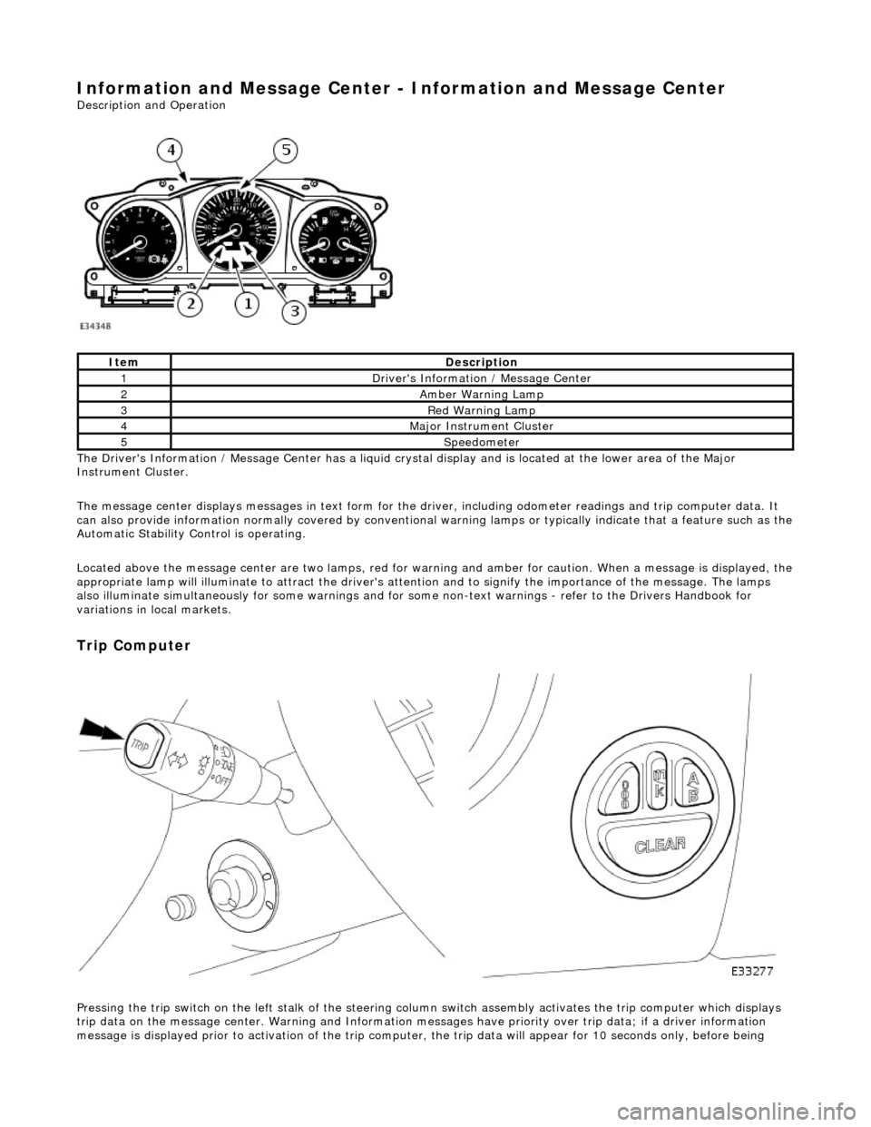
Information and Message Center - Information and Message Center
Description and Operation
The Driver's Information / Message Center has a liquid crystal display and is located at the lower area of the Major
Instrument Cluster.
The message center displays messages in text form for the driver, including odometer readings an d trip computer data. It
can also provide information normally covered by conventional wa rning lamps or typically indicate that a feature such as the
Automatic Stability Control is operating.
Located above the message center are two lamps, red for warning and amber for caution. When a message is displayed, the
appropriate lamp will illuminate to attract the driver's attention and to signify the importance of the message. The lamps
also illuminate simultaneously for some warnings and for some non-text warnin gs - refer to the Drivers Handbook for
variations in local markets.
Trip Computer
Pressing the trip switch on the left stalk of the steering colu mn switch assembly activates the trip computer which displays
trip data on the message center. Warning and Information messages have priority ov er trip data; if a driver information
message is displayed prior to activation of the trip computer , the trip data will appear for 10 seconds only, before being
ItemDescription
1Driver's Information / Message Center
2Amber Warning Lamp
3Red Warning Lamp
4Major Instrument Cluster
5Speedometer
Page 1904 of 2490
Audio Unit - Audio System
Description and Operation
The choice of two entertainment system s is available; base or premium.
The base system comprises a radio cassette player with in tegral message display and "Phone Ready" controls for an
accessory telephone; door speakers and tweeters.
The premium system has the following additional components: power amplifier, CD autochanger, sub-woofer and 'A' post
tweeters fitted instead of front door tweeters.
Both systems can be operated remotely by use of switches loca ted on the steering wheel and have an electrically operated
aerial.
Telephone controls incorporated in the ra dio cassette unit facilitate inclusion of the GSM hands free telephone system
available as optional equipment.
After diagnostic or repair operations, refer to the Sound System Handbook for setting-up procedures and operation.