Page 1102 of 2490
9.
Connect
the evaporative emission canister purge valve
electrical connector.
10. Check and if necessary to p up the cooling system.
11. Install the engine cover.
For additional informat ion, refer to Section 501
-05
Interior
Trim and Ornament
ation
.
Page 1103 of 2490
E
ngine Emission Control - Exhaust Ma
nifold to Exhaust Gas Recirculation
(EGR) Valve Tube
Re
moval and Installation
Remov
al
1.
R
emove the engine cover.
For additional informat ion, refer to Section 501
-0
5 Interior
Trim and Ornamen
tation
.
2. Di
sconnect the evaporative emission canister purge valve
electrical connector.
3. De
tach and reposition the evaporative emission canister purge
valve.
4. Di
sconnect the exhaust gas recirc
ulation (EGR) valve electrical
connector.
5. Remove the exhaust manifold to EGR valve tube retaining
bolts.
Remove an
d discard the exhaust manifold to EGR valve
tube gasket.
Page 1105 of 2490
4.
Att
ach the evaporative emission canister purge valve.
1. Tighten to 6 Nm.
5. Conne
ct the evaporative emission canister purge valve
electrical connector.
6. Install the engine cover.
For additional informat ion, refer to Section 501
-0
5 Interior
Trim and Ornamen
tation
.
Page 1109 of 2490

P
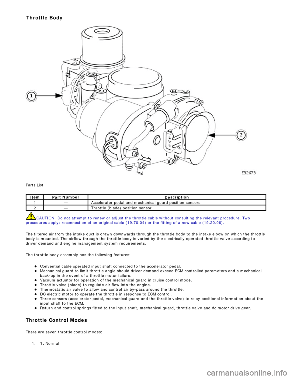
arts List
CAUTION: Do not attempt to renew or adjust the throttle cable without consulting the relevant procedure. Two
procedures apply: reconnection of an original cable (19.70.04) or the fitting of a new cable (19.20.06).
The filtered air from the intake duct is drawn downwards through the throttle body to the intake elbow on which the throttle
body is mounted. The airflow through the throttle body is vari ed by the electrically operated throttle valve according to
driver demand and engine mana gement system requirements.
The throttle body assembly has the following features:
Con
vential cable operated input shaft connected to the accelerator pedal.
M
echanical guard to limit throttle angl
e should driver demand exceed ECM co ntrolled parameters and a mechanical
back-up in the event of a throttle motor failure.
Vacuum actuator for operation of the mech anical guard in cru
ise control mode.
Thr
ottle valve (blade) to regula
te air flow into the engine.
Thermostatic air valve to allow and con
t
rol air by-pass around the throttle.
D
C electric motor to operate the thro
ttle in response to ECM control.
Three
sensors (accelerator pedal, mechan
ical guard and the throttle valve) to relay positional information about the
input shaft to the ECM.
R
eturn and control springs fitted to th
e input shaft, mechanical guard, thro ttle valve and dc motor drive gear.
Throttle Cont
rol Modes
There are seven throttle control
modes:
1. 1. Normal
It
em
Par
t Number
De
scription
1—Acce
lerator pedal and mechanic
al guard position sensors
2—Throttl
e (blade)
position sensor
Throttle Body
Page 1116 of 2490

Intake Air Distribution and Filtering - Air Cleaner
Remo
val and Installation
Remov
a
l
1.
Op
en the engine compartment and fit paintwork protection
sheets.
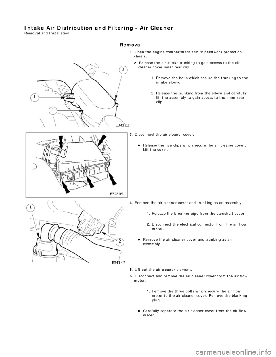
2. Relea
se the air intake trunking
to gain access to the air
cleaner cover inner rear clip
1. Remove the bolts which secure the trunking to the intake elbow.
2. Release the trunking from the elbow and carefully lift the assembly to gain access to the inner rear
clip.
3. Disc
onnect the air cleaner cover.
R
e
lease the five clips which se
cure the air cleaner cover.
Lift the cover.
4. Re
move the air cleaner cover an
d trunking as an assembly.
1. Release the breather pipe from the camshaft cover.
2. Disconnect the electrical connector from the air flow meter.
Re
move the air cleaner cover and trunking as an
assembly.
5. Lift out the air cleaner element.
6. Disconnect and remove the air cleaner cover from the air flow
meter.
1. Remove the three bolts which secure the air flow
meter to the air cleaner co ver. Remove the blanking
plug.
Carefull y separate the ai
r clea
ner cover from the air flow
meter.
Page 1138 of 2490
7. Re
move engine covers
8. Disc onne
ct electrical connector from each fuel injector.
9. Disc
onnect fuel feed hose.
1. Use special tool 310-044 (JD 182).
10. Disconnect fuel return hose.
1. Use special tool 310-054 (JD 203).
Page 1140 of 2490
In
stallation
15.
Cle
an manifold and mating faces on cylinder heads.
1. Where necessary, install blanking plate to intake elbow.
Inst al
l new gasket.
Inst
al
l bolts (18-24Nm).
2. Inst al
l intake elbow to intake manifold.
1. Install new seal.
2. Install seven bolts.
3. Install new seals to the eight intake manifold ports. Ensure the
seals are fully seated.
4. Inst al
l intake manifold.
1. Install ten bolts.
5. Connect fuel feed hose to fuel rail feed pipe. Ensure hose is
fully installed.
6. Connect fuel return hose to fuel rail return pipe. Ensure hose is
fully installed.
7. Con n
ect electrical connectors to fuel injectors.
8. Install left-hand support brac ket to intake elbow and re-
connect pipework.
1. Install bolt.
Page 1155 of 2490

T
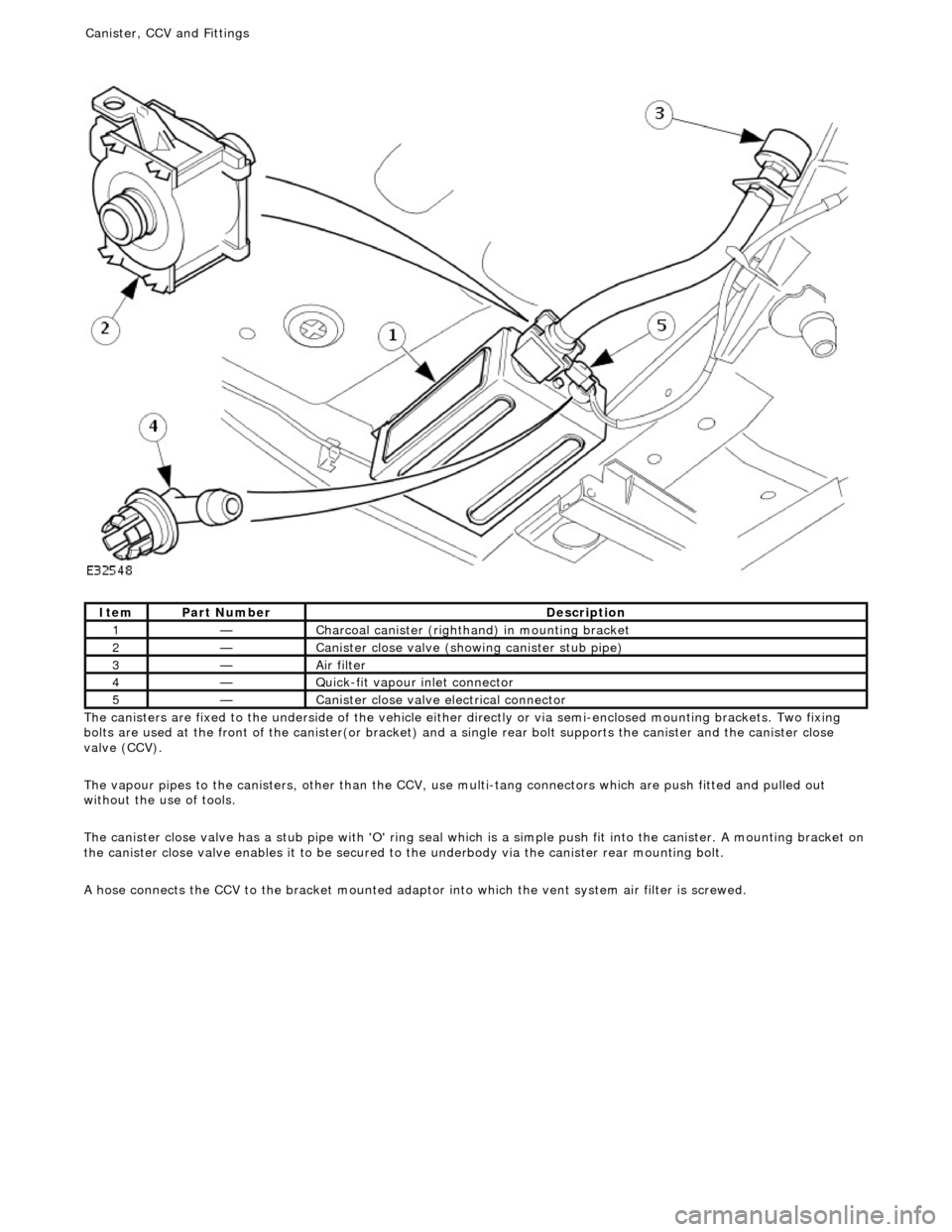
he canisters are fixed to the underside of the vehicle either
directly or via semi-enclosed mounting brackets. Two fixing
bolts are used at the front of the canister(or bracket) and a single rear bolt supports the canister and the canister close
valve (CCV).
The vapour pipes to the canisters, other than the CCV, use multi-tang connectors which are push fitted and pulled out
without the use of tools.
The canister close valve has a stub pipe with 'O' ring seal wh ich is a simple push fit into the canister. A mounting bracket on
the canister close valve enables it to be secured to the underbody via the canister rear mounting bolt.
A hose connects the CCV to the bracket mounted adaptor into which the vent system air filter is screwed.
It
em
Par
t Number
De
scription
1—C
harcoal canister (righthand) in mounting bracket
2—Cani
ster close valve (showi
ng canister stub pipe)
3—Ai
r filter
4—Q
uick-fit vapour inlet connector
5—Cani
ster close valve electrical connector
Canister, CCV an
d Fittings