1998 JAGUAR X308 ECU
[x] Cancel search: ECUPage 2377 of 2490
Supplemental Restraint System - Side Air Bag Module
Removal and Installation
Removal
• WARNINGS:
A SIDE AIR BAG MUST ONLY BE RENEWED IF A FAULT FLAG HAS OCCURRED. IN THE EVENT OF SIDE AIR BAG
DEPLOYMENT DUE TO SIDE IMPACT, THE COMPLETE SEAT MUST BE RENEWED.
FOLLOWING TEN YEARS IN SERVICE, AN AIR BAG MO DULE MUST BE REMOVED AND DISPOSED OF IN THE
APPROVED MANNER, AND A NEW AIR BAG MUST BE FITTED.
FOLLOWING DISCONNECTION OF THE BATTERY, A PERIOD OF AT LEAST FIFTEEN MINUTES MUST BE ALLOWED TO
ELAPSE BEFORE DISCONNECTING THE SINGLE-POINT SENSIN G (SPS) UNIT AND AN ELAPSE OF 2 MINUTES ALLOWED
BEFORE DISCONNECTING ANY OTHER SUPPLEMENTARY RESTRAINT SYSTEM COMPONENT.
AIR BAGS CONTAIN A CHEMICAL IRRITANT. IF AN AIR BAG IS RENEWED, THE DISCARDED UNIT MUST BE DISPOSED
OF IN ACCORDANCE WITH CURRENT SAFETY PROCEDURES.
IN THE EVENT OF A FAULT RUPTURING THE 10A BATTERY SUPPLY FUSE (F4 LOCATED IN THE FUSE-BOX AT THE
DRIVER'S END OF THE FASCIA), THE FUSE MUST NOT BE RENEWED UNTIL THE AIRBAG/SRS SYSTEM HAS BEEN DE-
ACTIVATED. FUSES OF ANY OTHER VALUE MUST NEVER BE USED, AS THIS CAN CAUSE DISARM FAILURE.
1. Remove battery cover and disc onnect ground cable from
battery terminal. Refer to 86.15.19.
2. Remove seat from vehi cle. Refer to 76.70.01.
3. Remove seat back fini sher. Refer to 76.70.09.
4. Partially remove squab cover and foam pad for access. Refer to
76.70.15
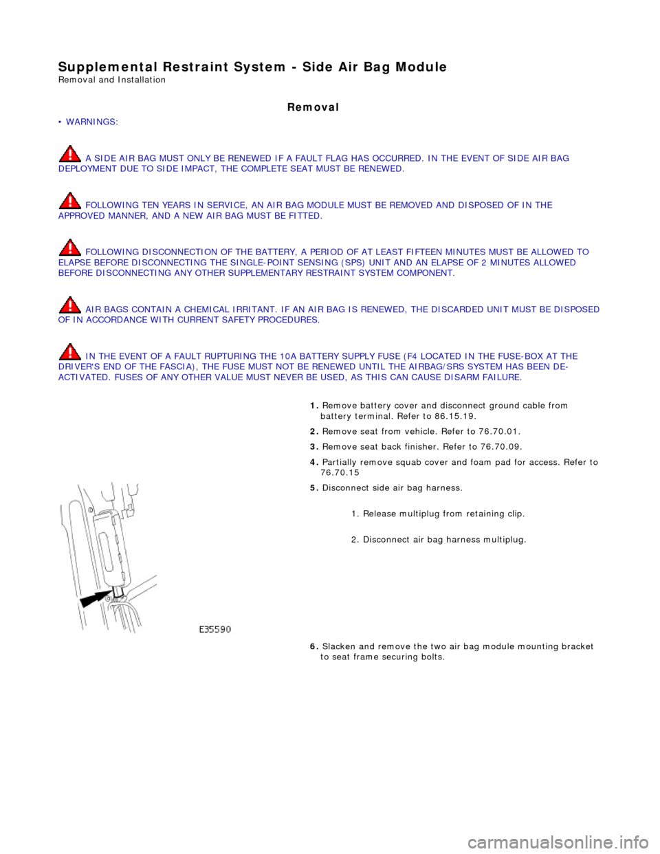
5. Disconnect side air bag harness.
1. Release multiplug from retaining clip.
2. Disconnect air ba g harness multiplug.
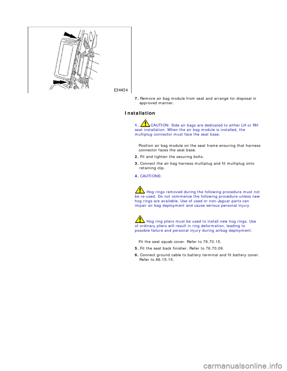
6. Slacken and remove the two air bag module mounting bracket
to seat frame securing bolts.
Page 2378 of 2490
Installation
7. Remove air bag module from seat and arrange for disposal in
approved manner.
1. CAUTION: Side air bags are de dicated to either LH or RH
seat installation. When the air bag module is installed, the
multiplug connector must face the seat base.
Position air bag module on the seat frame ensuring that harness
connector faces the seat base.
2. Fit and tighten the securing bolts.
3. Connect the air bag harness mult iplug and fit multiplug onto
retaining clip.
4. CAUTIONS:
Hog rings removed during the following procedure must not
be re-used. Do not commence the following procedure unless new hog rings are availabl e. Use of used or non-Jaguar parts can
impair air bag deployment and cause serious personal injury.
Hog ring pliers must be used to install new hog rings. Use
of ordinary pliers will result in ring deformation, leading to
possible failure and personal in jury during airbag deployment.
Fit the seat squab cover. Refer to 76.70.15.
5. Fit the seat back finisher. Refer to 76.70.09.
6. Connect ground cable to battery terminal and fit battery cover.
Refer to 86.15.15.
Page 2379 of 2490
Supplemental Restraint System - Side Impact Sensor
Removal and Installation
Removal
• WARNINGS:
FOLLOWING DISCONNECTION OF THE BA TTERY, A PERIOD OF AT LEAST FIFTEEN MINUTES MUST BE ALLOWED TO
ELAPSE BEFORE DISCONNECTING THE SINGLE-POINT SENSING (SPS) UNIT.
IN THE EVENT OF A FAULT RUPTURING THE 10A BATTER Y SUPPLY FUSE (F4 LOCATED IN THE FUSE-BOX AT THE
DRIVER'S END OF THE FASCIA), THE FUSE MUST NOT BE RENEWED UNTIL THE AIRBAG/SRS SYSTEM HAS BEEN DE-
ACTIVATED. FUSES OF ANY OTHER VALUE MUST NEVER BE USED, AS THIS CAN CAUSE DISARM FAILURE.
Installation
1. Remove battery cover and disconnect ground cable from battery
terminal. Refer to 86.15.19.
2. Remove'B' post trim pa d. Refer to 76.13.08.
3. Remove seat belt upper anchor and seat belt guide. Refer to
76.73.10
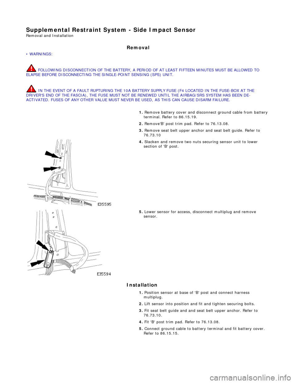
4. Slacken and remove two nuts securing sensor unit to lower
section of 'B' post.
5. Lower sensor for access, disco nnect multiplug and remove
sensor.
1. Position sensor at base of 'B' post and connect harness
multiplug.
2. Lift sensor into position and fit and tighten securing bolts.
3. Fit seat belt guide and and seat belt upper anchor. Refer to
76.73.10.
4. Fit 'B' post trim pad. Refer to 76.13.08.
5. Connect ground cable to battery terminal and fit battery cover.
Refer to 86.15.15.
Page 2393 of 2490
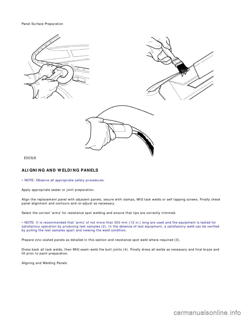
Panel Surface Preparation
ALIGNING AND WELDING PANELS
• NOTE: Observe all appropriate safety procedures.
Apply appropriate sealer or joint preparation.
Align the replacement panel with adjacent panels, secure with clamps, MIG tack welds or self tapping screws. Finally check
panel alignment and contours and re-adjust as necessary.
Select the correct 'arms' for resistance spot welding and ensure that tips are correctly trimmed.
• NOTE: It is recommended that 'arms' of not more than 300 mm (12 in.) long ar e used and the equipment is tested for
satisfactory operation by producing test samples (2). In the ab sence of test equipment, a satisfactory weld can be verified
by pulling the test sa mples apart and viewing the weld condition.
Prepare zinc coated panels as detailed in this section and resistance spot weld where required (3).
Dress back all tack welds, then MIG seam-weld the butt joints (4). Finally dress all welds as necessary and final braze and
fill prior to paint preparation.
Ali
gning and Welding Panels
Page 2409 of 2490
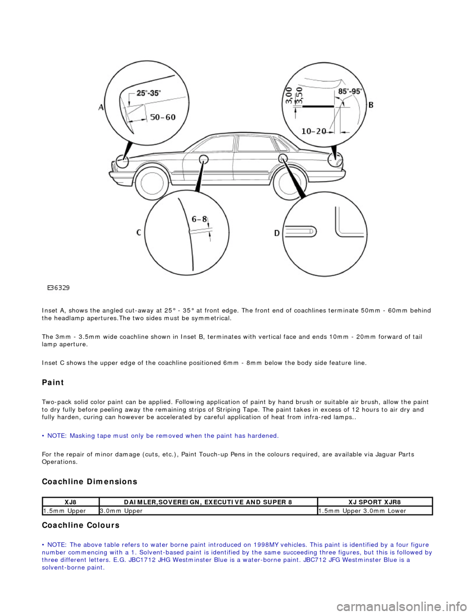
Inset A, shows the angled cut-away at 25° - 35° at front edge. The front end of coachlines terminate 50mm - 60mm behind
the headlamp apertures.The two sides must be symmetrical.
The 3mm - 3.5mm wide coachline shown in Inset B, terminates with vertical face and ends 10mm - 20mm forward of tail
lamp aperture.
Inset C shows the upper edge of th e coachline positioned 6mm - 8mm be low the body side feature line.
Paint
Two-pack solid color paint can be applied. Following application of paint by hand brus h or suitable air brush, allow the paint
to dry fully before peeling away the remain ing strips of Striping Tape. The paint takes in excess of 12 hours to air dry and
fully harden, curing can however be accelerated by careful application of heat from infra-red lamps..
• NOTE: Masking tape must only be removed when the paint has hardened.
For the repair of minor damage (cuts, et c.), Paint Touch-up Pens in the colours required, are available via Jaguar Parts
Operations.
Coachline Dimensions
Coachline Colours
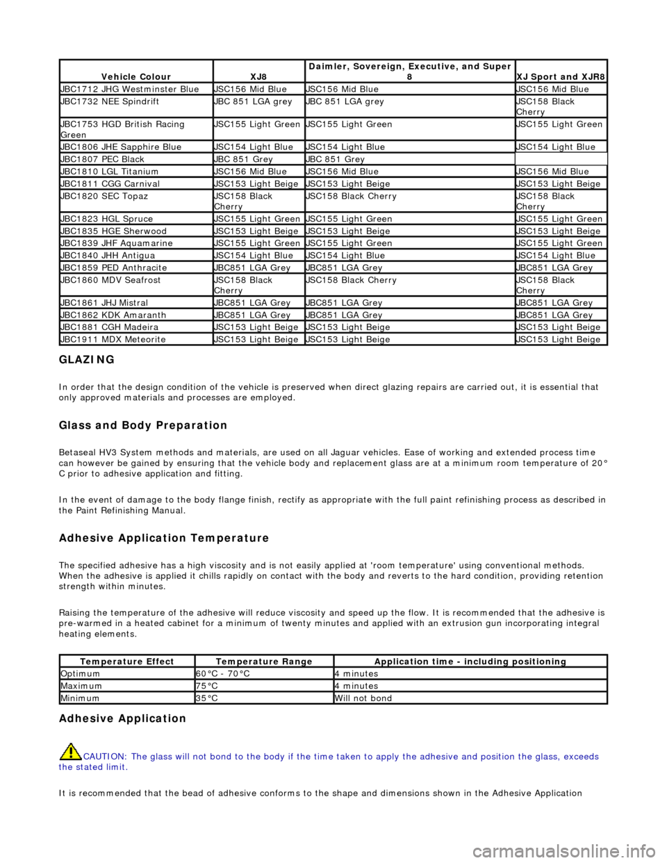
• NOTE: The above table refers to water borne paint introduced on 1998MY vehicles. This paint is identified by a four figure
number commencing with a 1. Solvent-based paint is identified by the same succeeding three figures, but this is followed by three different letters. E.G. JBC1712 JHG Westminster Blue is a water-borne paint. JBC712 JFG Westminster Blue is a
solvent-borne paint.
XJ8DAIMLER,SOVEREIGN, EXECUTIVE AND SUPER 8XJ SPORT XJR8
1.5mm Upper3.0mm Upper1.5mm Upper 3.0mm Lower
Page 2410 of 2490
GLAZING
In order that the design condition of the vehicle is preserved when direct glazing repairs are carried out, it is essential that
only approved materials an d processes are employed.
Glass and Body Preparation
Betaseal HV3 System methods an d materials, are used on all Jaguar vehicles . Ease of working and extended process time
can however be gained by ensuring that the vehicle body and replacement glass are at a minimum room temperature of 20°
C prior to adhesive a pplication and fitting.
In the event of damage to the body flange finish, rectify as appropriate with the full paint refinishing process as described in
the Paint Refinishing Manual.
Adhesive Application Temperature
The specified adhesive has a high viscosity and is not easily applied at 'room te mperature' using conventional methods.
When the adhesive is applied it chills ra pidly on contact with the body and reverts to the hard condition, providing retention
strength with in minutes.
Raising the temperature of the adhesive will reduce viscosity an d speed up the flow. It is recommended that the adhesive is
pre-warmed in a heated cabinet for a mini mum of twenty minutes and applied with an extrusion gun incorporating integral
heating elements.
Adhesive Application
CAUTION: The glass will not bond to the body if the time taken to apply the adhesive and position the glass, exceeds
the stated limit.
It is recommended that the be ad of adhesive conforms to the shape and dimensions shown in the Adhesive Application
Vehicle ColourXJ8Daimler, Sovereign, Executive, and Super
8XJ Sport and XJR8
JBC1712 JHG Westminster BlueJSC156 Mid BlueJSC156 Mid BlueJSC156 Mid Blue
JBC1732 NEE SpindriftJBC 851 LGA greyJBC 851 LGA greyJSC158 Black
Cherry
JBC1753 HGD British Racing
GreenJSC155 Light GreenJSC155 Light GreenJSC155 Light Green
JBC1806 JHE Sapphire BlueJSC154 Light BlueJSC154 Light BlueJSC154 Light Blue
JBC1807 PEC BlackJBC 851 GreyJBC 851 Grey
JBC1810 LGL TitaniumJSC156 Mid BlueJSC156 Mid BlueJSC156 Mid Blue
JBC1811 CGG CarnivalJSC153 Light BeigeJSC153 Light BeigeJSC153 Light Beige
JBC1820 SEC TopazJSC158 Black
CherryJSC158 Black CherryJSC158 Black
Cherry
JBC1823 HGL SpruceJSC155 Light GreenJSC155 Light GreenJSC155 Light Green
JBC1835 HGE SherwoodJSC153 Light BeigeJSC153 Light BeigeJSC153 Light Beige
JBC1839 JHF AquamarineJSC155 Light GreenJSC155 Light GreenJSC155 Light Green
JBC1840 JHH AntiguaJSC154 Light BlueJSC154 Light BlueJSC154 Light Blue
JBC1859 PED AnthraciteJBC851 LGA GreyJBC851 LGA GreyJBC851 LGA Grey
JBC1860 MDV SeafrostJSC158 Black
CherryJSC158 Black CherryJSC158 Black
Cherry
JBC1861 JHJ MistralJBC851 LGA GreyJBC851 LGA GreyJBC851 LGA Grey
JBC1862 KDK AmaranthJBC851 LGA GreyJBC851 LGA GreyJBC851 LGA Grey
JBC1881 CGH MadeiraJSC153 Light BeigeJSC153 Light BeigeJSC153 Light Beige
JBC1911 MDX MeteoriteJSC153 Light BeigeJSC153 Light BeigeJSC153 Light Beige
Temperature EffectTemperature RangeApplication time - including positioning
Optimum60°C - 70°C4 minutes
Maximum75°C4 minutes
Minimum35°CWill not bond
Page 2411 of 2490
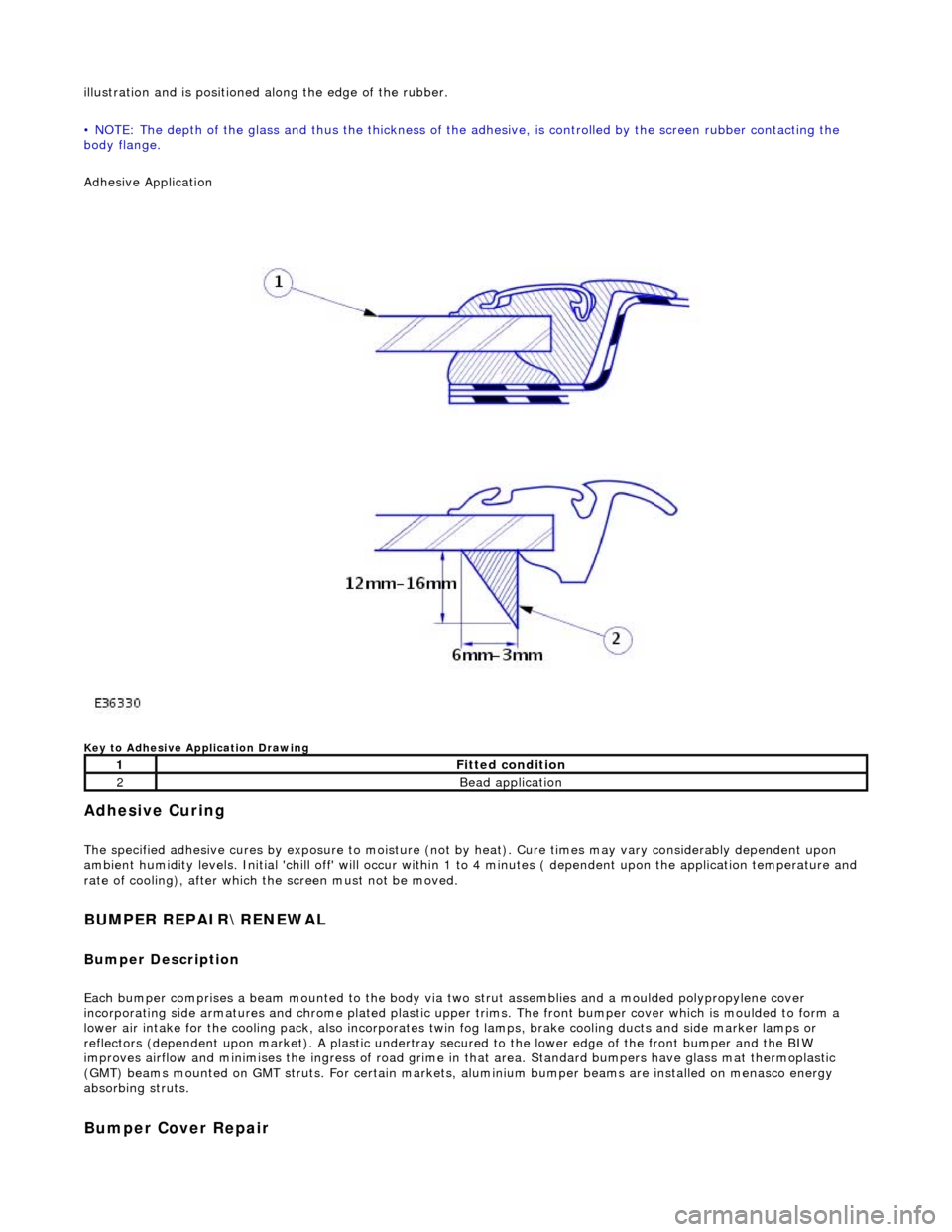
illustration and is positioned along the edge of the rubber.
• NOTE: The depth of the glass and thus the thickness of the ad hesive, is controlled by the screen rubber contacting the
body flange.
Adhesive Application
Key to Adhesive Application Drawing
Adhesive Curing
The specified adhesive cures by exposure to moisture (not by heat). Cure times may vary considerably dependent upon
ambient humidity levels. Initial 'chill off' will occur within 1 to 4 minutes ( dependent upon the application temperature and
rate of cooling), after which the screen must not be moved.
BUMPER REPAIR\RENEWAL
Bumper Description
Each bumper comprises a beam mounte d to the body via two strut assemblies and a moulded polypropylene cover
incorporating side armatures and chrome plated plastic upper trims. The front bumper cover which is moulded to form a
lower air intake for the cooling pack, also incorporates twin fog lamps, brake cooling ducts and side marker lamps or
reflectors (dependent upon market). A plastic undertray secured to the lower edge of the front bumper and the BIW
improves airflow and minimises the ingres s of road grime in that area. Standard bumpers have glass mat thermoplastic
(GMT) beams mounted on GMT struts. For certain markets, aluminium bumper beams are installed on menasco energy
absorbing struts.
Bumper Cover Repair
1Fitted condition
2Bead application
Page 2420 of 2490
lever mechanism driven by an electric motor. A sliding roof control module (SRCM) controls the motor in response to
selections made on the roof console switch , or input from the security system for automatic closing. Both the motor and the SRCM are accessed by removing the roof console.In the event of an electrical failure the sliding roof can be manually
operated. This is achieved by inserting a wide bladed screwdriver into a slot in the motor drive gear and turning clockwise to open or counter clockwise to close the sliding roof.
• NOTE: The drive gear becomes disengaged from the motor during manual operation. Before restoring electrical operation
the drive gear must be rotated one quarter turn in the reverse direction to re-engage the motor.
The SRCM is held in position by clips and has two electrical connectors in terfacing with the motor and the roof console
switch/security system. Prior to installing a new SRCM, the sun ro of must be in a neutral closed position. This provides the
SRCM with a sliding roof datum, to ensure accurate and consistent operation. Obstacle sensin g operates on closing in the
slide mode only. If the sliding roof lid encounters an ob struction between 4mm and 200mm from the closed position, the
SRCM detects increased motor load and reve rses the motor, driving the sliding roof to the fully open position. The sliding
roof lid surround seal has a metal inner sect ion which will deform on removal. If removed, this seal must be discarded and a
new seal must be installed on the lid using a Jaguar approved crimping tool.