Page 2335 of 2490
Roof Opening Panel - Roof Opening Panel Module
Removal and Installation
Removal
1. Remove cover from battery and disconnect ground cable from
battery terminal.
2. Remove sliding roof trim panel for access. Refer to 76.82.19.
3. Using a drive key or screwdriver in the motor gearbox slot,
manually move the sliding roof towards the closed position.
4. Position the sliding roof with an 8mm gap between the driven
lever and the guide rail step.
5. Remove roof console for ac cess. Refer to 76.13.69.90.
6. Release sun visor from support and position at cantrail.
7. Remove visor support securing screw and remove support from
header.
8. Disconnect harness multiplugs from sliding roof control
module.
9. Carefully withdraw adjacent sectio n of flange finisher and edge
of headlining sufficient to prov ide access to control module.
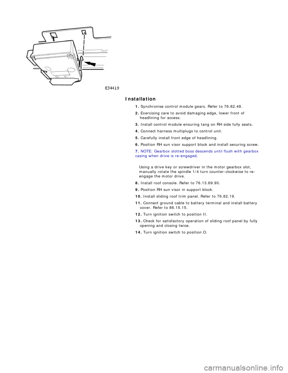
10. Depressing retaining tang on RH side of module, lower that
side and release from tang on sliding roof frame.
Page 2336 of 2490

Installation
1. Synchronise control module gears. Refer to 76.82.48.
2. Exercising care to avoid da maging edge, lower front of
headlining for access.
3. Install control module ensuring tang on RH side fully seats.
4. Connect harness multiplugs to control unit.
5. Carefully install front edge of headlining.
6. Position RH sun visor support bl ock and install securing screw.
7. NOTE: Gearbox slotted boss descends until flush with gearbox
casing when drive is re-engaged.
Using a drive key or screwdriver in the motor gearbox slot,
manually rotate the spindle 1/4 turn counter-clockwise to re-
engage the motor drive.
8. Install roof console. Refer to 76.13.69.90.
9. Position RH sun visor in support block.
10. Install sliding roof trim panel. Refer to 76.82.19.
11. Connect ground cable to batter y terminal and install battery
cover. Refer to 86.15.15.
12. Turn ignition switch to position II.
13. Check for satisfactory operation of sliding roof panel by fully
opening and closing twice.
14. Turn ignition switch to position O.
Page 2337 of 2490
Roof Opening Panel - Roof Opening Panel Motor
Removal and Installation
Removal
Installation
1. Remove battery cover and disc onnect ground cable from
battery terminal. Refer to 86.15.19.
2. Remove roof console for ac cess. Refer to 76.13.69.90.
3. Disconnect sliding roof panel motor multiplug from control
module.
4. slacken and remove sliding roof panel motor securing screws.
5. Withdraw motor assembly and remove plastic mountings.
1. Fit plastic mountings to motor.
2. Position and align motor in slid ing roof frame, ensuring that
motor body locates in outer tubes and gear engages inner
cables.
Page 2338 of 2490
3. Fit and tighten motor securing screws.
4. Connect motor harness multiplug to control module.
5. Using a drive key or screwdriver in the motor gearbox slot,
manually rotate the spindle 1/4 turn counter-clockwise to re-
engage the motor drive.
6. Fit roof console. Refer to 76.13.69.90.
7. Connect ground cable to battery terminal and fit battery cover.
Refer to 86.15.15.
Page 2343 of 2490
Bumpers -
Torques
ComponentNm
Bolts securing bumper beam to strut39 - 51
Bolts securing bumper guide to body15,5 - 20,5
Bolts securing energy absorbing strut to body22 - 28
Bolts securing non-energy absorbing strut to body15,5 - 20,5
Page 2344 of 2490

Bumpers - Front Bumper
Removal and Installation
Removal
WARNING: ENSURE THAT ALL PERSONNEL AND EQUIPMENT ARE CLEAR OF AREA BEFORE OPERATING RAMP.
1. Position vehicle on 4-post ramp.
2. Remove battery cover and disc onnect ground cable from
battery terminal. Refer to 86.15.19
3. Remove radiator surround and grill. Refer to 76.55.15 and
76.55.03.
4. Raise ramp to working height.
5. Using wheel-free lifts, remove front wheels.
6. Remove wheelarch liners for access.
7. Remove undertray. Refer to 76.22.90.
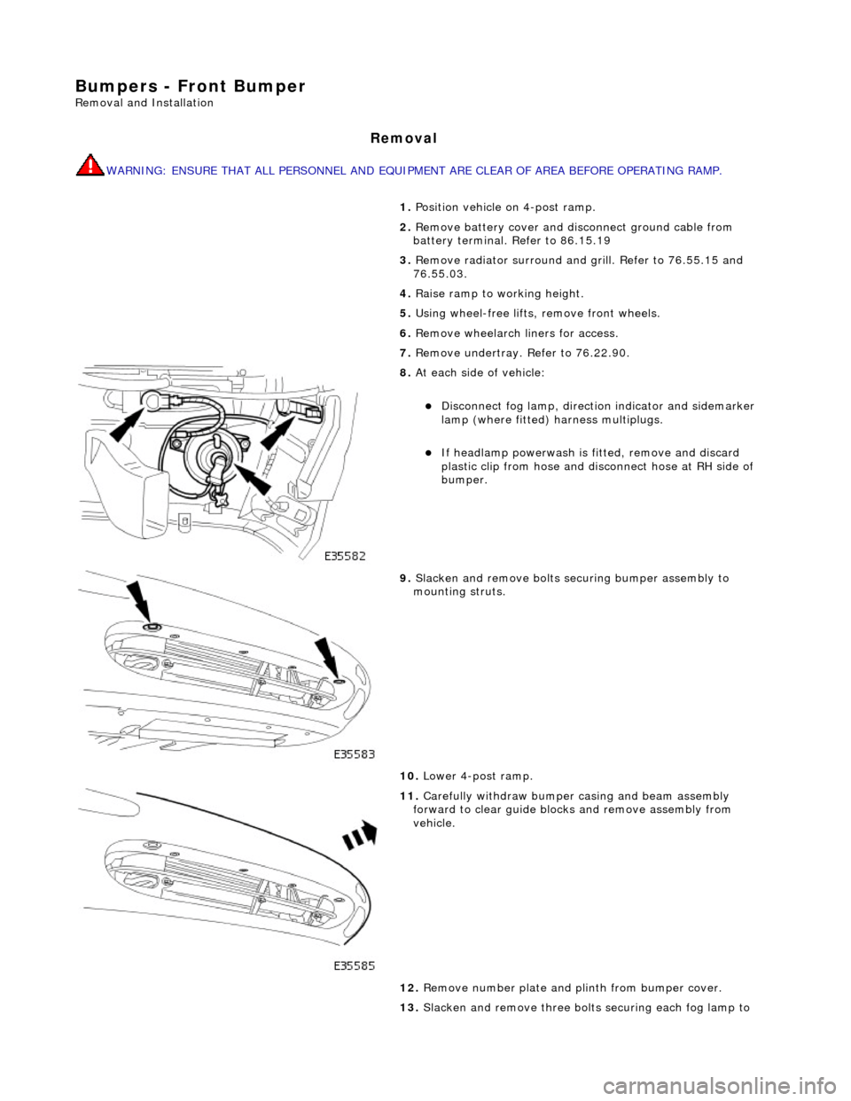
8. At each side of vehicle:
Disconnect fog lamp, directio n indicator and sidemarker
lamp (where fitted) harness multiplugs.
If headlamp powerwash is fitted, remove and discard
plastic clip from hose and disconnect hose at RH side of
bumper.
9. Slacken and remove bolts securing bumper assembly to
mounting struts.
10. Lower 4-post ramp.
11. Carefully withdraw bumper casing and beam assembly
forward to clear guide blocks and remove assembly from
vehicle.
12. Remove number plate and plinth from bumper cover.
13. Slacken and remove three bolts securing each fog lamp to
Page 2345 of 2490
bumper cover and remove both lamps from cover.
14. Release sidemarker lamp/refle ctor clips and remove both
lamps/reflectors from bumper cover.
15. Remove direction indicators fr om bumper assembly. Refer to
Section 417.01.
16. Remove powerwash jet assemb lies and hoses from top of
bumper assembly. Refer to Section 501-16.
17. Remove bumper blades.
1. Slacken and remove three screws securing each blade
to bumper cover.
2. Slide each blade forward to release two side tangs from cover and remove blade from bumper.
18. Rotate three splitter vane fasteners 1/4 turn counter-
clockwise and remove splitter vane from air intake.
19. Release tangs securing brake cooling ducts to cover and
remove ducts from bumper.
Page 2346 of 2490
In
stallation
20
. Remove an
d discard four scrive
ts securing upper section of
air intake to beam.
21 . D
rill out rivets securing uppe
r section of cover to bumper
beam.
22. Withdraw bumper beam from cover.
1. Position beam in cover, ensuring that tangs locate correctly in
beam slots.
2. Using new fir tree fast eners, scrivets and rivets, secure beam
to bumper cover.
3. Install fog lights, direction indicators, and side marker
lamps/reflectors in bumper cover.
4. Fit chrome blades to top of casing locating tangs in slots and fit
and tighten securing screws.
5. Fit powerwash jet assemblies to bumper cover. Refer to
Section 501.16.
6. Fit bumper assembly to vehicle. Refer to operations in this
section.
7. Position splitter vane in air intake and secure by rotating
fasteners 1/4 turn clockwise.
8. Fit number plate and plinth.
9. Connect ground cable to battery terminal and fit battery cover.
Refer to 86.15.15.