Page 2300 of 2490

Installation
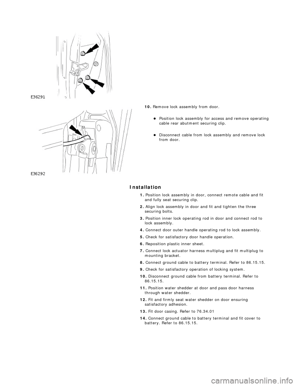
10. Remove lock assembly from door.
Position lock assembly for access and remove operating
cable rear abutment securing clip.
Disconnect cable from lock assembly and remove lock
from door.
1. Position lock assembly in door, connect remote cable and fit
and fully seat securing clip.
2. Align lock assembly in door and fit and tighten the three
securing bolts.
3. Position inner lock operating ro d in door and connect rod to
lock assembly.
4. Connect door outer handle operating rod to lock assembly.
5. Check for satisfactory door handle operation.
6. Reposition plastic inner sheet.
7. Connect lock actuator harness multiplug and fit multiplug to
mounting bracket.
8. Connect ground cable to battery terminal. Refer to 86.15.15.
9. Check for satisfactory operation of locking system.
10. Disconnect ground cable from battery terminal. Refer to
86.15.15.
11. Position water shedder at d oor and pass door harness
through water shedder.
12. Fit and firmly seat water shedder on door ensuring
satisfactory adhesion.
13. Fit door casing. Refer to 76.34.01
14. Connect ground cable to battery terminal and fit cover to
battery. Refer to 86.15.15.
Page 2301 of 2490
Handles, Locks, Latches and Entry Systems - Exterior Rear Door Handle
Removal and Installation
Removal
1. Remove battery cover and disco nnect earth cable from battery
terminal. Refer to 86.15.19.
2. Remove rear door casing. Refer to 76.34.04.
3. Carefully withdraw water shedder passing harness through it
and remove water shedder from door.
4. Place water shedder adhesive face down on clean dry plastic
sheet.
5. Disconnect door handle operating link from lock assembly.
6. Firmly holding door handle, slacken and remove the two
securing bolts.
7. Withdraw handle mounting brac ket from door interior and
remove handle from door.
Page 2302 of 2490
Installation
8. Remove lock link rod from door handle assembly.
1. Fit link rod to handle assembly.
2. Position handle assembly on door.
3. Position mounting bracket on insi de of door and connect lock
link rod.
4. Fit and tighten mounting bracket securing bolts.
5. Reposition PVC inner sheet in door.
6. Check for satisfactory door handle operation.
7. Connect ground cable to battery terminal. Refer to 86.15.15.
8. From driver door check for satisfactory operation of locking
system.
9. Disconnect ground cable from battery terminal. Refer to
86.15.15.
10. Ensure that water shedder contact area of door is clean and
dry.
11. Position water shedder at door and carefully pass harness
through.
12. Fit and firmly seat water shedder on door ensuring
satisfactory adhesion.
13. Fit door casing. Refer to 76.34.01.
14. Fit door casing veneer panel. Refer to 76.47.11.
15. Fit ground cable to battery term inal and fit cover to battery.
Refer to 86.15.15.
Page 2304 of 2490
Installation
9. Remove door inner cheater finisher.
10. Slacken and remove the door glass guide securing bolts and
position guide for access.
11. Slacken and remove lock mechanism securing bolts.
12. Carefully withdraw lock me chanism from door, remove
cable rear abutment clip and disconnect cable.
13. Remove lock mechan ism from vehicle.
Page 2305 of 2490

1.
Position lock mechanism at door and connect operating cable.
2. Fit and fully seat cable rear abutment securing clip.
3. Fit and fully seat lock mechanism in door and fit and tighten
securing bolts.
4. Align glass guide and fit and tighten securing bolts.
5. Fit and fully seat inner cheater finisher.
6. Align and connect inner operating rod to lock mechanism.
7. Fit outer door handle operating rod to lock
8. Check for satisfactory door handle operation.
9. Reposition inner plastic sheet.
10. Connect lock actuator harness multiplug and fit to mounting
bracket.
11. Connect ground cable to battery terminal. Refer to 86.15.15.
12. From driver door, check for satisfactory operation of locking
system.
13. Disconnect ground cable from battery terminal. Refer to
86.15.19.
14. Ensure that water shedder contact area of door is clean and
dry.
15. Position water shedder at d oor and carefully pass door
harness through.
16. Fit and firmly seat water shedde r on door ensuring satifactory
adhesion.
17. Fit door casing. Refer to 76.34.04.
18. Fit door casing veneer panel. Refer to 76.47.12.
19. Connect ground cable to battery terminal and fit battery
cover. Refer to 86.15.15.
Page 2306 of 2490

Wipers and Washers - Wipers and Washers
Description and Operation
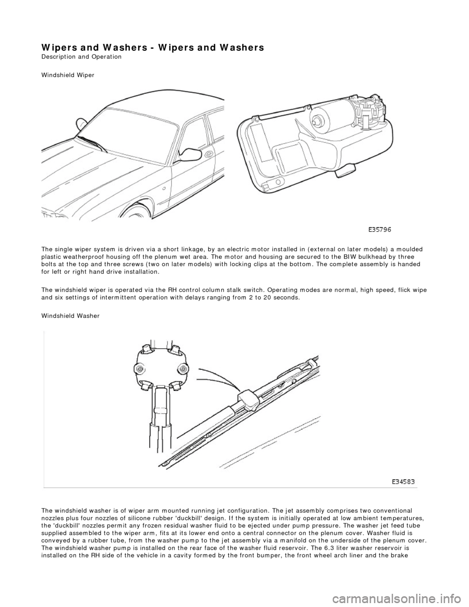
Windshield Wiper
The single wiper system is driven via a sh ort linkage, by an electric motor installed in (external on later models) a moulded
plastic weatherproof housing o ff the plenum wet area. The motor and housing are secured to the BIW bulkhead by three
bolts at the top and three screws (two on later models) with locking clips at the bottom. The complete assembly is handed
for left or right hand drive installation.
The windshield wiper is operated via the RH control column stalk switch. Operating modes are normal, high speed, flick wipe
and six settings of intermittent operation with delays ranging from 2 to 20 seconds.
Windshield Washer
The windshield washer is of wiper arm mounted running jet configuration. The je t assembly comprises two conventional
nozzles plus four nozzles of silicone rubbe r 'duckbill' design. If the system is initially operated at low ambient temperatures ,
the 'duckbill' nozzles permit an y frozen residual washer fluid to be ejected un der pump pressure. The washer jet feed tube
supplied assembled to the wiper ar m, fits at its lower end onto a central connector on the pl enum cover. Washer fluid is
conveyed by a rubber tube, from the washer pump to the jet assembly via a manifold on the underside of the plenum cover.
The windshield washer pump is installed on the rear face of the washer fluid reservoir. The 6.3 liter washer reservoir is
installed on the RH side of th e vehicle in a cavity formed by the front bu mper, the front wheel arch liner and the brake
Page 2308 of 2490
The rain sensor unit is installed on the inside of the windshield within the rear view mirror stem cover. The unit is secured t o
the glass by a special adhesive th at facilitates service removal. When installing a rain sensor unit, it must be positioned in
the clear circle within the obscuration band.
The rain sensor control module is a non- serviceable unit installed in the engine bay cool box and connected to the rain
sensor unit and the body processor module.
Page 2310 of 2490
Wipers and Washers - Headlamp Washer Jet Removal and Installation
Removal
Installation
1.
Raise front of vehicle and support on stands.
2. Remove RH front wheel.
3. Remove RH front wheelarch liner. Refer to Section 501-02.
4. Remove and discard plastic clip from washer fluid hose and
disconnect hose from rear of jet assembly.
5. Slacken and remove screw securing cover to jet assembly and
remove cover.
6. Remove jet assembly from bumper.
1. Slacken and remove screws securing jet assembly to bumper.
2. Slide jet assembly forward and remove from bumper.
1. Position jet assembly in bumper an d fit and tighten securing screws.
2. Fit cover over jet assembly and fit and tighten securing screw.
3. Connect hose onto rear of jet asse mbly and secure with new plastic
clip.
4. Fit wheelarch liner. Refer to Section 501-02.
5. Fit road wheel.
6. Remove stands and lower vehicle onto wheels.