1998 ISUZU TROOPER warning
[x] Cancel search: warningPage 883 of 3573
POWER ASSISTED BRAKE SYSTEM 5C – 5
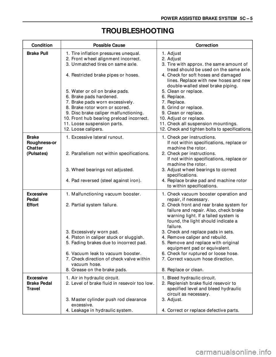
TROUBLESHOOTING
Condition Possible Cause Correction
Brake Pull1. Tire inflation pressures unequal. 1. Adjust
2. Front wheel alignment incorrect. 2. Adjust
3. Unmatched tires on same axle. 3. Tire with approx. the same amount of
tread should be used on the same axle.
4. Restricted brake pipes or hoses. 4. Check for soft hoses and damaged
lines. Replace with new hoses and new
double-walled steel brake piping.
5. Water or oil on brake pads. 5. Clean or replace.
6. Brake pads hardened. 6. Replace.
7. Brake pads worn excessively. 7. Replace.
8. Brake rotor worn or scored. 8. Grind or replace.
9. Disc brake caliper malfunctioning. 9. Clean or replace.
10. Front hub bearing preload incorrect. 10. Adjust or replace.
11. Loose suspension parts. 11. Check all suspension mountings.
12. Loose calipers. 12. Check and tighten bolts to specifications.
Brake 1. Excessive lateral runout. 1. Check per instructions.
Roughness-orIf not within specifications, replace or
Chattermachine the rotor.
(Pulsates)2. Parallelism not within specifications. 2. Check per instructions.
If not within specifications, replace or
machine the rotor.
3. Wheel bearings not adjusted. 3. Adjust wheel bearings to correct
specifications.
4. Pad reversed (steel against iron). 4. Replace brake pad and machine rotor
to within specifications.
Excessive 1. Malfunctioning vacuum booster. 1. Check vacuum booster operation and
Pedal repair, if necessary.
Effort2. Partial system failure. 2. Check front and rear brake system for
failure and repair. Also, check brake
warning light. If a failed system is
found, the light should indicate a
failure.
3. Excessively worn pad. 3. Check and replace pads in sets.
4. Piston in caliper stuck or sluggish. 4. Remove caliper and rebuild.
5. Fading brakes due to incorrect pad. 5. Remove and replace with original
equipment pad or equivalent.
6. Vacuum leak to vacuum booster. 6. Check for ruptured or loose hose.
7. Check direction of check valve within 7. Correct vacuum hose direction.
vacuum hose.
8. Grease on the brake pads. 8. Replace or clean.
Excessive 1. Air in hydraulic circuit. 1. Bleed hydraulic circuit.
Brake Pedal 2. Level of brake fluid in resevoir too low. 2. Replenish brake fluid resevoir to
Travelspecified level and bleed hydraulic
circuit as necessary.
3. Master cylinder push rod clearance 3. Adjust.
excessive.
4. Leakage in hydraulic system. 4. Correct or replace defective parts.
Page 932 of 3573
5C – 54 POWER ASSISTED BRAKE SYSTEM
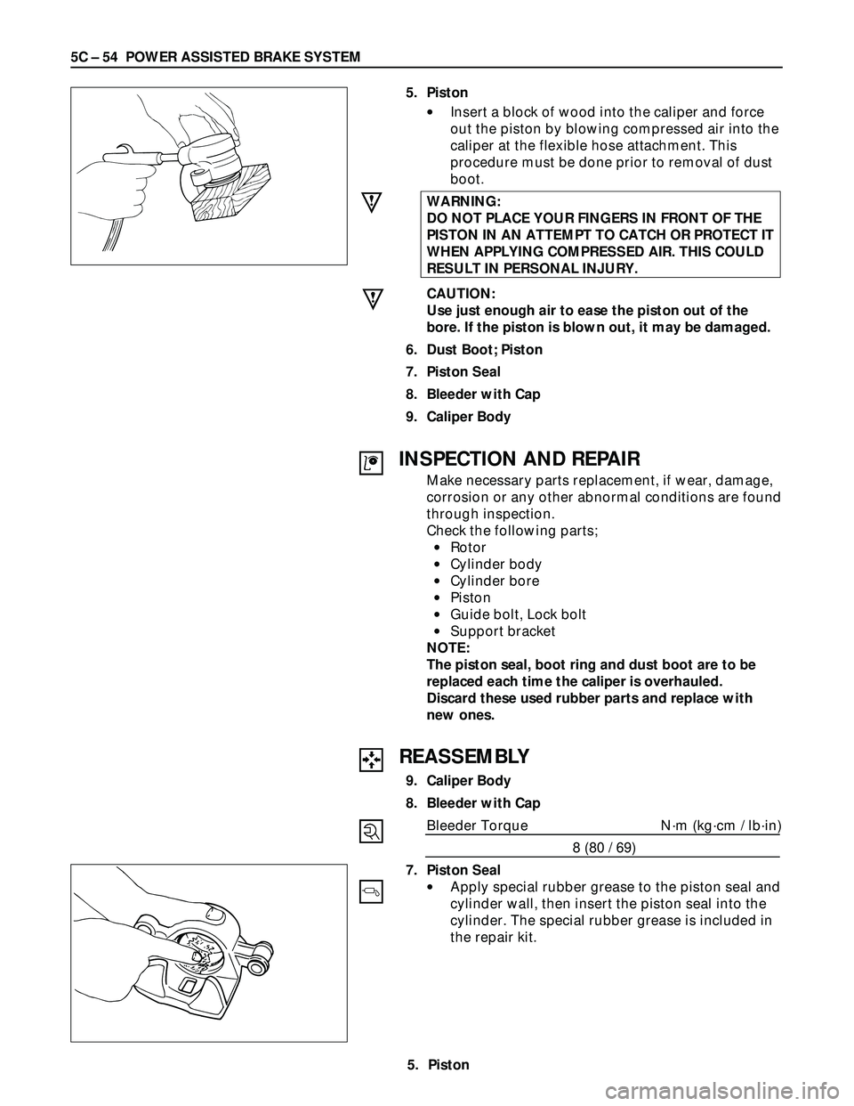
5. Piston
•Insert a block of wood into the caliper and force
out the piston by blowing compressed air into the
caliper at the flexible hose attachment. This
procedure must be done prior to removal of dust
boot.
WARNING:
DO NOT PLACE YOUR FINGERS IN FRONT OF THE
PISTON IN AN ATTEMPT TO CATCH OR PROTECT IT
WHEN APPLYING COMPRESSED AIR. THIS COULD
RESULT IN PERSONAL INJURY.
CAUTION:
Use just enough air to ease the piston out of the
bore. If the piston is blown out, it may be damaged.
6. Dust Boot; Piston
7. Piston Seal
8. Bleeder with Cap
9. Caliper Body
REASSEMBLY
9. Caliper Body
8. Bleeder with Cap
Bleeder Torque N·m (kg·cm / lb·in)
8 (80 / 69)
7. Piston Seal
•Apply special rubber grease to the piston seal and
cylinder wall, then insert the piston seal into the
cylinder. The special rubber grease is included in
the repair kit.
INSPECTION AND REPAIR
Make necessary parts replacement, if wear, damage,
corrosion or any other abnormal conditions are found
through inspection.
Check the following parts;
•Rotor
•Cylinder body
•Cylinder bore
•Piston
•Guide bolt, Lock bolt
•Support bracket
NOTE:
The piston seal, boot ring and dust boot are to be
replaced each time the caliper is overhauled.
Discard these used rubber parts and replace with
new ones.
5. Piston
Page 941 of 3573
POWER ASSISTED BRAKE SYSTEM 5C – 63
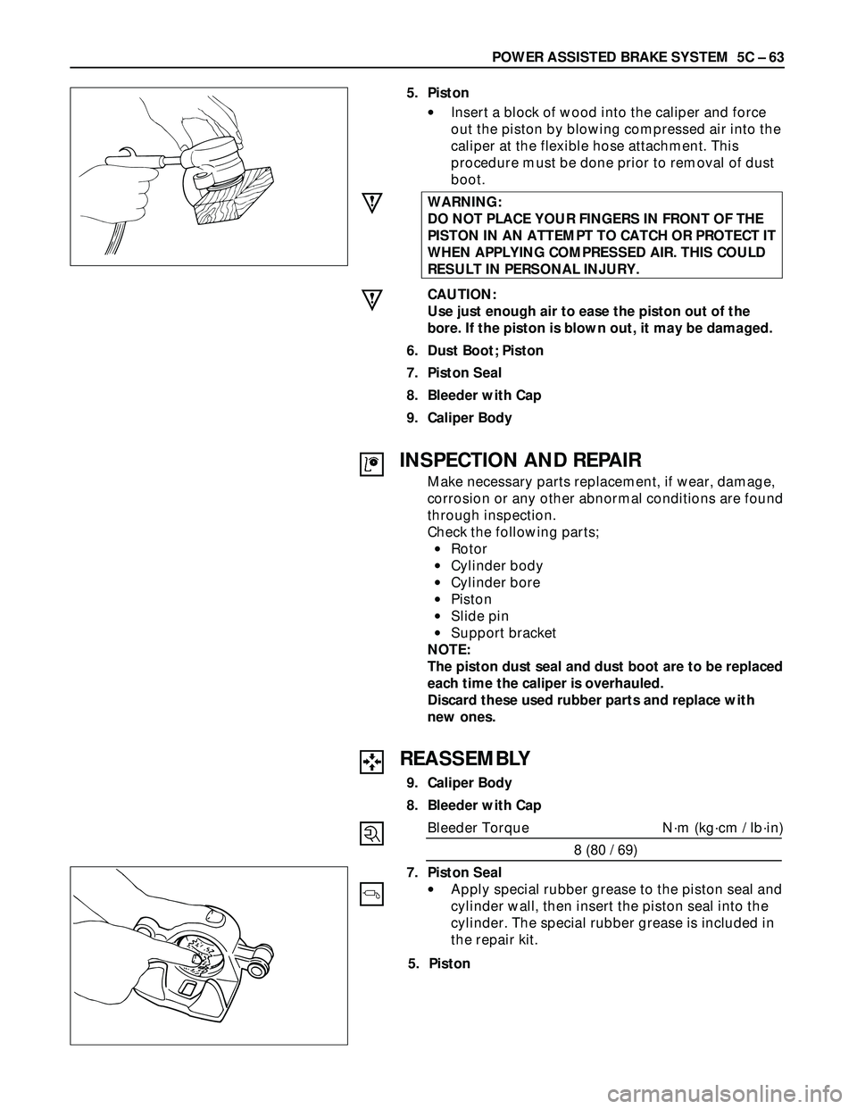
5. Piston
•Insert a block of wood into the caliper and force
out the piston by blowing compressed air into the
caliper at the flexible hose attachment. This
procedure must be done prior to removal of dust
boot.
WARNING:
DO NOT PLACE YOUR FINGERS IN FRONT OF THE
PISTON IN AN ATTEMPT TO CATCH OR PROTECT IT
WHEN APPLYING COMPRESSED AIR. THIS COULD
RESULT IN PERSONAL INJURY.
CAUTION:
Use just enough air to ease the piston out of the
bore. If the piston is blown out, it may be damaged.
6. Dust Boot; Piston
7. Piston Seal
8. Bleeder with Cap
9. Caliper Body
REASSEMBLY
9. Caliper Body
8. Bleeder with Cap
Bleeder Torque N·m (kg·cm / lb·in)
8 (80 / 69)
7. Piston Seal
•Apply special rubber grease to the piston seal and
cylinder wall, then insert the piston seal into the
cylinder. The special rubber grease is included in
the repair kit.
INSPECTION AND REPAIR
Make necessary parts replacement, if wear, damage,
corrosion or any other abnormal conditions are found
through inspection.
Check the following parts;
•Rotor
•Cylinder body
•Cylinder bore
•Piston
•Slide pin
•Support bracket
NOTE:
The piston dust seal and dust boot are to be replaced
each time the caliper is overhauled.
Discard these used rubber parts and replace with
new ones.
5. Piston
Page 946 of 3573
PARKING BRAKES 5D Ð 1
SECTION 5D
PARKING BRAKES
CONTENTS
PAGE
Service Precaution .............................................................................................................5D- 1
Main Data and Specifications ........................................................................................... 5D- 2
Service Standard................................................................................................................ 5D- 2
Servicing ............................................................................................................................. 5D- 3
Fixing Torque ...................................................................................................................... 5D- 5
General Description ........................................................................................................... 5D- 6
On-Vehicle Service .............................................................................................................5D- 7
Parking Brake Lever Replacement ............................................................................... 5D- 7
Parking Brake Cable ...................................................................................................... 5D- 9
SERVICE PRECAUTION
WARNING:
IF SO EQUIPPED WITH A SUPPLEMENTAL RESTRAINT SYSTEM (SRS), REFER TO THE SRS COMPONENT
AND WIRING LOCATION VIEW IN ORDER TO DETERMINE WHETHER YOU ARE PERFORMING SERVICE ON
OR NEAR THE SRS COMPONENTS OR THE SRS WIRING. WHEN YOU ARE PERFORMING SERVICE ON OR
NEAR THE SRS COMPONENTS OR THE SRS WIRING, REFER TO THE SRS SERVICE INFORMATION.
FAILURE TO FOLLOW WARNINGS COULD RESULT IN POSSIBLE AIR BAG DEPLOYMENT, PERSONAL
INJURY, OR OTHERWISE UNNEEDED SRS SYSTEM REPAIRS.
CAUTION:
Always use the correct fastener in the proper location. When you replace a fastener, use ONLY the exact
part number for that application. ISUZU will call out those fasteners that require a replacement after
removal. ISUZU will also call out the fasteners that require thread lockers or thread sealant. UNLESS
OTHERWISE SPECIFIED, do not use supplemental coatings (Paints, greases, or other corrosion inhibitors)
on threaded fasteners or fastener joint interfaces. Generally, such coatings adversely affect the fastener
torque and the joint clamping force, and may damage the fastener. When you install fasteners, use the
correct tightening sequence and specification. Following these instructions can help you avoid damage to
parts and systems.
Page 951 of 3573
5D Ð 6 PARKING BRAKES
GENERAL DESCRIPTION
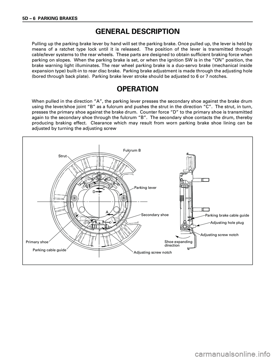
Pulling up the parking brake lever by hand will set the parking brake. Once pulled up, the lever is held by
means of a ratchet type lock until it is released. The position of the lever is transmitted through
cable/lever systems to the rear wheels. These parts are designed to obtain sufficient braking force when
parking on slopes. When the parking brake is set, or when the ignition SW is in the ÒONÓ position, the
brake warning light illuminates. The rear wheel parking brake is a duo-servo brake (mechanical inside
expansion type) built-in to rear disc brake. Parking brake adjustment is made through the adjusting hole
(bored through back plate). Parking brake lever stroke should be adjusted to 6 or 7 notches.
OPERATION
When pulled in the direction ÒAÓ, the parking lever presses the secondary shoe against the brake drum
using the lever/shoe joint ÒBÓ as a fulcrum and pushes the strut in the direction ÒCÓ. The strut, in turn,
presses the primary shoe against the brake drum. Counter force ÒDÓ to the primary shoe is transmitted
again to the secondary shoe through the fulcrum ÒBÓ. The secondary shoe contacts the drum, thereby
producing braking effect. Clearance which may result from worn parking brake shoe lining can be
adjusted by turning the adjusting screw
Parking lever
Strut
Primary shoe
Parking cable guide
Adjusting screw notch
Secondary shoe
DC
A
Fulcrum B
Parking brake cable guide
Adjusting hole plug
Adjusting screw notch
Shoe expanding
direction
Page 958 of 3573

6A±2
ENGINE MECHANICAL
Piston and Connecting Rod 6A±77. . . . . . . . . . . . . . .
Piston, Connecting Rod and Associate
Parts 6A±77. . . . . . . . . . . . . . . . . . . . . . . . . . . . . . . .
Disassembly 6A±77. . . . . . . . . . . . . . . . . . . . . . . . . .
Inspection and Repair 6A±78. . . . . . . . . . . . . . . . . .
Reassembly 6A±82. . . . . . . . . . . . . . . . . . . . . . . . . .
Cylinder Block 6A±85. . . . . . . . . . . . . . . . . . . . . . . . . .
Cylinder Block and Associated Parts 6A±85. . . . .
Disassembly 6A±85. . . . . . . . . . . . . . . . . . . . . . . . . .
Inspection and Repair 6A±86. . . . . . . . . . . . . . . . . .
Reassembly 6A±87. . . . . . . . . . . . . . . . . . . . . . . . . .
Main Data and Specification 6A±90. . . . . . . . . . . . . .
Special Tool 6A±96. . . . . . . . . . . . . . . . . . . . . . . . . . . .
Service Precaution
WARNING: I F S O E Q U IPPED WITH A
SUPPLEMENTAL RESTRAINT SYSTEM (SRS),
REFER TO THE SRS COMPONENT AND WIRING
LOCATION VIEW IN ORDER TO DETERMINE
WHETHER YOU ARE PERFORMING SERVICE ON OR
NEAR THE SRS COMPONENTS OR THE SRS
WIRING. WHEN YOU ARE PERFORMING SERVICE
ON OR NEAR THE SRS COMPONENTS OR THE SRS
WIRING, REFER TO THE SRS SERVICE
INFORMATION. FAILURE TO FOLLOW WARNINGS
COULD RESULT IN POSSIBLE AIR BAG
DEPLOYMENT, PERSONAL INJURY, OR
OTHERWISE UNNEEDED SRS SYSTEM REPAIRS.
CAUTION: Always use the correct fastener in the
proper location. When you replace a fastener, use
ONLY the exact part number for that application.
ISUZU will call out those fasteners that require a
replacement after removal. ISUZU will also call out
the fasteners that require thread lockers or thread
sealant. UNLESS OTHERWISE SPECIFIED, do not
use supplemental coatings (Paints, greases, or other
corrosion inhibitors) on threaded fasteners or
fastener joint interfaces. Generally, such coatings
adversely affect the fastener torque and the joint
clamping force, and may damage the fastener. When
you install fasteners, use the correct tightening
sequence and specifications. Following these
instructions can help you avoid damage to parts and
systems.
Page 1054 of 3573
ENGINE COOLING6B±1
ENGINE
ENGINE COOLING
CONTENTS
Service Precaution 6B±1. . . . . . . . . . . . . . . . . . . . . .
General Description 6B±2. . . . . . . . . . . . . . . . . . . . .
Diagnosis 6B±5. . . . . . . . . . . . . . . . . . . . . . . . . . . . . .
Draining and Refilling Cooling System 6B±6. . . . .
Water Pump 6B±7. . . . . . . . . . . . . . . . . . . . . . . . . . . .
Water Pump and Associated Parts 6B±7. . . . . . .
Removal 6B±7. . . . . . . . . . . . . . . . . . . . . . . . . . . . .
Inspection 6B±7. . . . . . . . . . . . . . . . . . . . . . . . . . . .
Installation 6B±7. . . . . . . . . . . . . . . . . . . . . . . . . . . .
Thermostat 6B±8. . . . . . . . . . . . . . . . . . . . . . . . . . . . .
Thermostat and Associated Parts 6B±8. . . . . . . .
Removal 6B±8. . . . . . . . . . . . . . . . . . . . . . . . . . . . .
Inspection 6B±8. . . . . . . . . . . . . . . . . . . . . . . . . . . . Installation 6B±8. . . . . . . . . . . . . . . . . . . . . . . . . . . .
Radiator 6B±9. . . . . . . . . . . . . . . . . . . . . . . . . . . . . . .
Radiator and Associated Parts 6B±9. . . . . . . . . .
Removal 6B±9. . . . . . . . . . . . . . . . . . . . . . . . . . . . .
Inspection 6B±10. . . . . . . . . . . . . . . . . . . . . . . . . . . .
Installation 6B±11. . . . . . . . . . . . . . . . . . . . . . . . . . . .
Drive Belt and Cooling Fan 6B±12. . . . . . . . . . . . . . .
Drive Belt and Associated Parts 6B±12. . . . . . . . .
Inspection 6B±12. . . . . . . . . . . . . . . . . . . . . . . . . . . .
Installation 6B±12. . . . . . . . . . . . . . . . . . . . . . . . . . . .
Main Data and Specifications 6B±13. . . . . . . . . . . . .
Special Tool 6B±14. . . . . . . . . . . . . . . . . . . . . . . . . . . .
Service Precaution
WARNING: I F S O E Q U IPPED WITH A
SUPPLEMENTAL RESTRAINT SYSTEM (SRS),
REFER TO THE SRS COMPONENT AND WIRING
LOCATION VIEW IN ORDER TO DETERMINE
WHETHER YOU ARE PERFORMING SERVICE ON OR
NEAR THE SRS COMPONENTS OR THE SRS
WIRING. WHEN YOU ARE PERFORMING SERVICE
ON OR NEAR THE SRS COMPONENTS OR THE SRS
WIRING, REFER TO THE SRS SERVICE
INFORMATION. FAILURE TO FOLLOW WARNINGS
COULD RESULT IN POSSIBLE AIR BAG
DEPLOYMENT, PERSONAL INJURY, OR
OTHERWISE UNNEEDED SRS SYSTEM REPAIRS.
CAUTION: Always use the correct fastener in the
proper location. When you replace a fastener, use
ONLY the exact part number for that application.
ISUZU will call out those fasteners that require a
replacement after removal. ISUZU will also call out
the fasteners that require thread lockers or thread
sealant. UNLESS OTHERWISE SPECIFIED, do not
use supplemental coatings (Paints, greases, or other
corrosion inhibitors) on threaded fasteners or
fastener joint interfaces. Generally, such coatings
adversely affect the fastener torque and the joint
clamping force, and may damage the fastener. When
you install fasteners, use the correct tightening
sequence and specifications. Following these
instructions can help you avoid damage to parts and
systems.
Page 1059 of 3573
6B±6
ENGINE COOLING
Draining and Refilling Cooling
System
Before draining the cooling system, inspect the system
and perform any necessary service to ensure that it is
clean, does not leak and is in proper working order. The
engine coolant (EC) level should be between the ªMINº
and ªMAXº lines of reserve tank when the engine is cold.
If low, check for leakage and add EC up to the ªMAXº line.
There should not be any excessive deposit of rust or
scales around the radiator cap or radiator filler hole, and
the EC should also be free from oil.
Replace the EC if excessively dirty.
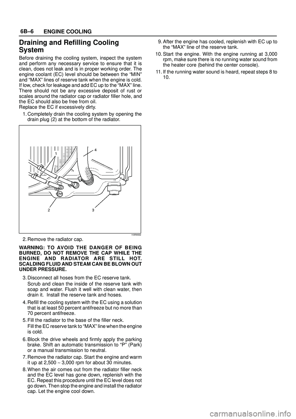
1. Completely drain the cooling system by opening the
drain plug (2) at the bottom of the radiator.
110RW002
2. Remove the radiator cap.
WARNING: T O AV O I D T H E D A N G E R O F B E I N G
BURNED, DO NOT REMOVE THE CAP WHILE THE
ENGINE AND RADIATOR ARE STILL HOT.
SCALDING FLUID AND STEAM CAN BE BLOWN OUT
UNDER PRESSURE.
3. Disconnect all hoses from the EC reserve tank.
Scrub and clean the inside of the reserve tank with
soap and water. Flush it well with clean water, then
drain it. Install the reserve tank and hoses.
4. Refill the cooling system with the EC using a solution
that is at least 50 percent antifreeze but no more than
70 percent antifreeze.
5. Fill the radiator to the base of the filler neck.
Fill the EC reserve tank to ªMAXº line when the engine
is cold.
6. Block the drive wheels and firmly apply the parking
brake. Shift an automatic transmission to ªPº (Park)
or a manual transmission to neutral.
7. Remove the radiator cap. Start the engine and warm
it up at 2,500 ~ 3,000 rpm for about 30 minutes.
8. When the air comes out from the radiator filler neck
and the EC level has gone down, replenish with the
EC. Repeat this procedure until the EC level does not
go down. Then stop the engine and install the radiator
cap. Let the engine cool down.9. After the engine has cooled, replenish with EC up to
the ªMAXº line of the reserve tank.
10. Start the engine. With the engine running at 3,000
rpm, make sure there is no running water sound from
the heater core (behind the center console).
11. If the running water sound is heard, repeat steps 8 to
10.