Page 1985 of 3573
6E±92
4JX1±TC ENGINE DRIVEABILITY AND EMISSIONS
Diagnostic Trouble Code (DTC) P1196 (Flash DTC 62)
Rail Pressure System High Warning
060RW178
Legend
(1) ECM
(2) Meter Panel
(3) Battery
(4) Oil Temp Sensor
(5) Rail Pressure Sensor
(6) Glow Relay
(7) Oil Rail
(8) Tech±2
(9) A/C Comp Relay
(10) RPCV
(11) Intake Air Temp Sensor
(12) Engine Coolant Temp Sensor
(13) MAP Sensor
(14) EGR Valve
(15) EGR Pressure Sensor(16) High Pressure Oil Pump
(17) Fuel Pump
(18) VSV
(19) EXH Throttle VSV1
(20) EXH Throttle VSV2
(21) EVRV
(22) Engine Harness Connector
(23) QWS Relay
(24) AP Sensor
(25) T.O.D
(26) ECT
(27) OBD
(28) TDC
(29) Injector
(30) Edge Filter
Page 1986 of 3573
 is built in the high
pressure oil circuit.
RPCV is an important device which is used to con")
6E±93 4JX1±TC ENGINE DRIVEABILITY AND EMISSIONS
Circuit Description
The rail pressure control valve (RPCV) is built in the high
pressure oil circuit.
RPCV is an important device which is used to control oil
pressure in the HEUI system.
The circuit receives current through Engine 15A fuse from
the battery, current flowing in the order of RPCV.
Action Taken When the DTC Sets
�The ECM will store conditions which were present
when the DTC was set as Freeze Frame and in the
Failure Records data.
Conditions for Clearing the MIL/DTC
�DTC P1196 can be cleared by using the Tech 2 ªClear
Infoº function or by disconnecting the ECM battery
feed.
Diagnostic Aids
Check for the following conditions:�Poor connection at ECM ± Inspect harness connectors
for backed-out terminals, improper mating, broken
locks, improperly formed or damaged terminals, and
poor terminal-to-wire connection.
�Damaged harness ± Inspect the wiring harness for
damage. If the harness appears to be OK, observe the
Rail Pressure Control display on the Tech 2 while
moving connectors and wiring harnesses related to the
Rail Pressure Control. A change in the Rail Pressure
Control display will indicate the location of the fault.
If DTC P1196 cannot be duplicated, the information
included in the Failure Records data can be useful in
determining vehicle mileage since the DTC was last set.
If it is determined that the DTC occurs intermittently.
Test Description
Number(s) below refer to the step number(s) on the
Diagnostic Chart.
2. Verifies that the fault is present.
DTC P1196 ± RP System High Warning�
StepActionValue(s)Ye sNo
1Was the ªOn-Board Diagnostic (OBD) System Checkº
performed?
ÐGo to Step 2
Go to OBD
System
Check
21. Engine is running.
2. Observe the ªRail Pressure Controlº display on the
Tech 2.
Is the action correct?
ÐGo to Step 4Go to Step 3
3Replace the RPCV.
Is the action complete?
ÐVerify repairGo to Step 4
41. Engine is running.
2. Review and record Tech 2 Failure Records data.
3. Operate the vehicle within Failure Records
conditions as noted.
4. Using a Tech 2, monitor ª DTCº info for DTC P1196.
Does the Tech 2 indicate DTC P1196 failed this
ignition?
ÐGo to Step 5Ð
51. Check the 2 way valve.
2. Observe the ªRP Controlº display on the Tech 2.
Is the action correct?
ÐGo to Step 4Go to Step 6
6Replace the 2 way valve.
Is the action complete?
ÐVerify repairÐ
Page 2002 of 3573
 P1217 (Flash DTC 36)
High Oil Temp Warning
060RW129
Circuit Description
The engine oil temperature (OT) sensor is a th")
6E±109 4JX1±TC ENGINE DRIVEABILITY AND EMISSIONS
Diagnostic Trouble Code (DTC) P1217 (Flash DTC 36)
High Oil Temp Warning
060RW129
Circuit Description
The engine oil temperature (OT) sensor is a thermistor
mounted on a oil manifold. The Engine Control Module
ECM applies a voltage (about 5 volts) through a pull-up
resistor to the OT signal circuit. When the engine oil is
cold, the sensor (thermistor) resistance is high, therefore
the ECM will measure a high signal voltage. As the
engine oil warms, the sensor resistance becomes lower,
and the OT signal voltage measured at the ECM drops.
Action Taken When the DTC Sets
�The ECM will store conditions which were present
when the DTC was set as Freeze Frame and in the
Failure Records data.
Conditions for Clearing the MIL/DTC
�DTC P1217 can be cleared by using the Tech 2 ªClear
Infoº function or by disconnecting the ECM battery
feed.
Diagnostic Aids
Check for the following conditions:
�Poor connection at ECM ± Inspect harness connectors
for backed-out terminals, improper mating, broken
locks, improperly formed or damaged terminals, and
poor terminal-to-wire connection.
�Damaged harness ± Inspect the wiring harness for
damage.
�High Oil Temperature Warning may sometimes be
given due to High Coolant Temp Warning. On this
occasion, recognize DTC P0217 and give priority to
High Coolant Temp Warning.
Page 2003 of 3573
Ye sNo
1Was the ªOn-Board Diagnostic (OBD) System Checkº
performed?
ÐGo to Step 2
Go to OBD")
6E±110
4JX1±TC ENGINE DRIVEABILITY AND EMISSIONS
DTC P1217 ± High Oil Temp Warning�
StepActionValue(s)Ye sNo
1Was the ªOn-Board Diagnostic (OBD) System Checkº
performed?
ÐGo to Step 2
Go to OBD
System
Check
21. Ignition ªON,º engine ªOFF.º
2. Observe the ªEng Cool Tempº display on the Tech 2.
Is the ªEng Cool Tempº below the specified value?
139�C
(282�F)
Go to Step 4Go to Step 3
31. Ignition ªON,º engine ªOFF.º
2. Review and record Tech 2 Failure Records data.
3. Using a Tech 2, monitor ª DTCº info for DTC P0217.
Does the Tech 2 indicate DTC P0217 failed this
ignition?
ÐGo to Step 4
Refer to
Diagnostic
Aids
41. Ignition ªON,º engine ªOFF.º
2. Review and record Tech 2 Failure Records data.
3. Operate the vehicle within Failure Records
conditions as noted.
4. Using a Tech 2, monitor ª DTCº info for DTC P1217.
Does the Tech 2 indicate DTC P1217 failed this
ignition?
ÐGo to Step 5
Refer to
Diagnostic
Aids
51. Measure the engine oil quantity by oil level gage.
2. If the engine oil is shortage, fill up it as necessary.
Was the engine oil is shortaged?
ÐVerify repairGo to Step 6
6Replace the oil temp sensor.
Is the action complete?
ÐVerify repairGo to Step 7
7Replace the oil cooler.
Is the action complete?
ÐVerify repairÐ
Page 2004 of 3573
 P0219 (Flash DTC 11)
Engine Over Speed Warning
060RW133
Circuit Description
The CKP reference signal is produced by th")
6E±111 4JX1±TC ENGINE DRIVEABILITY AND EMISSIONS
Diagnostic Trouble Code (DTC) P0219 (Flash DTC 11)
Engine Over Speed Warning
060RW133
Circuit Description
The CKP reference signal is produced by the crankshaft
position (CKP) sensor. During one crankshaft revolution,
CKP crankshaft reference pulses will be produced. The
Engine Control Module ECM uses the CKP reference
signal to calculate engine RPM and crankshaft position.
Action Taken When the DTC Sets
�The ECM will store conditions which were present
when the DTC was set as Freeze Frame and in the
Failure Records data.
Conditions for Clearing the MIL/DTC
�DTC P0219 can be cleared by using the Tech 2 ªClear
Infoº function or by disconnecting the ECM battery
feed.
Diagnostic Aids
Check for:
�Poor connection ± Inspect the CKP harness and
connectors for improper mating, broken locks,
improperly formed or damaged terminals, and poor
terminal-to-wire connection.
�Damaged X57 ± Inspect the X57 for damage.
DTC P0219 ± Engine Over Speed Warning�
StepActionValue(s)Ye sNo
1Was the ªOn-Board Diagnostic (OBD) System Checkº
performed?
ÐGo to Step 2
Go to OBD
System
Check
2Check the responsibility.
Was the driver responsibility?
ÐGo to Step 3Go to Chart 4
Page 2005 of 3573
 Action
31. Review and record Failure Records information.
2. Clear DTC P0219.
3")
6E±112
4JX1±TC ENGINE DRIVEABILITY AND EMISSIONS
DTC P0219 ± Engine Over Speed Warning������ ���
StepNo Ye s Value(s) Action
31. Review and record Failure Records information.
2. Clear DTC P0219.
3. Start the engine and idle for 1 minute.
4. Observe DTCs.
Is DTC P0219 set?
ÐGo to Step 4Ð
4Observe the AP value displayed on the Tech 2.
Is the AP value near the specified value?(Idling 720 r.p
.m) 0 %
Go to Step 3Go to Step 5
5Observe the Engine speed displayed on the Tech 2.
Is the Engine speed near the specified value?(Idling) 720 r.
p.m
Go to Step 7Go to Step 6
61. Check the CKP sensor.
2. Ignition ªON.º
3. Using a DVM, verify that 5 V reference and ground
are being supplied at the sensor connector (ECM
side).
Are 4-6 volts and ground available at the sensor?
ÐGo to Step 9Go to Step 7
71. Ignition ªON.º
2. With a DVM, backprobe the ECM connector 5 V
reference and ground connections.
Are 5 V reference and ground available at the ECM?
ÐGo to Step 8Go to Step 13
8Check 5 V reference or ground between the CKP
sensor and ECM and repair the open circuit, short to
ground or short to voltage.
Is the action complete?
ÐVerify repairÐ
91. Ignition ªOFF.º
2. Disconnect the ECM and CKP sensor.
3. Check for an open or a short to ground in the CKP
reference circuit between the CKP sensor
connector and the ECM harness connector.
4. If a problem is found, repair as necessary.
Was a problem found?
ÐVerify repairGo to Step 10
101. Reconnect the ECM and CKP sensor.
2. Connect a DVM to measure voltage on the CKP
reference circuit at the ECM connector.
3. Observe the voltage while cranking the engine.
Is the voltage near the specified value?
2.5 VGo to Step 13Go to Step 11
11Check the connections at the CKP sensor and replace
the terminals if necessary.
Did any terminals require replacement?
ÐVerify repairGo to Step 12
12Replace the CKP sensor.
Is the action complete?
ÐVerify repairÐ
13Check the connections at the ECM and replace the
terminals if necessary.
Did any terminals require replacement?
ÐVerify repair Go to Step 14
Page 2006 of 3573
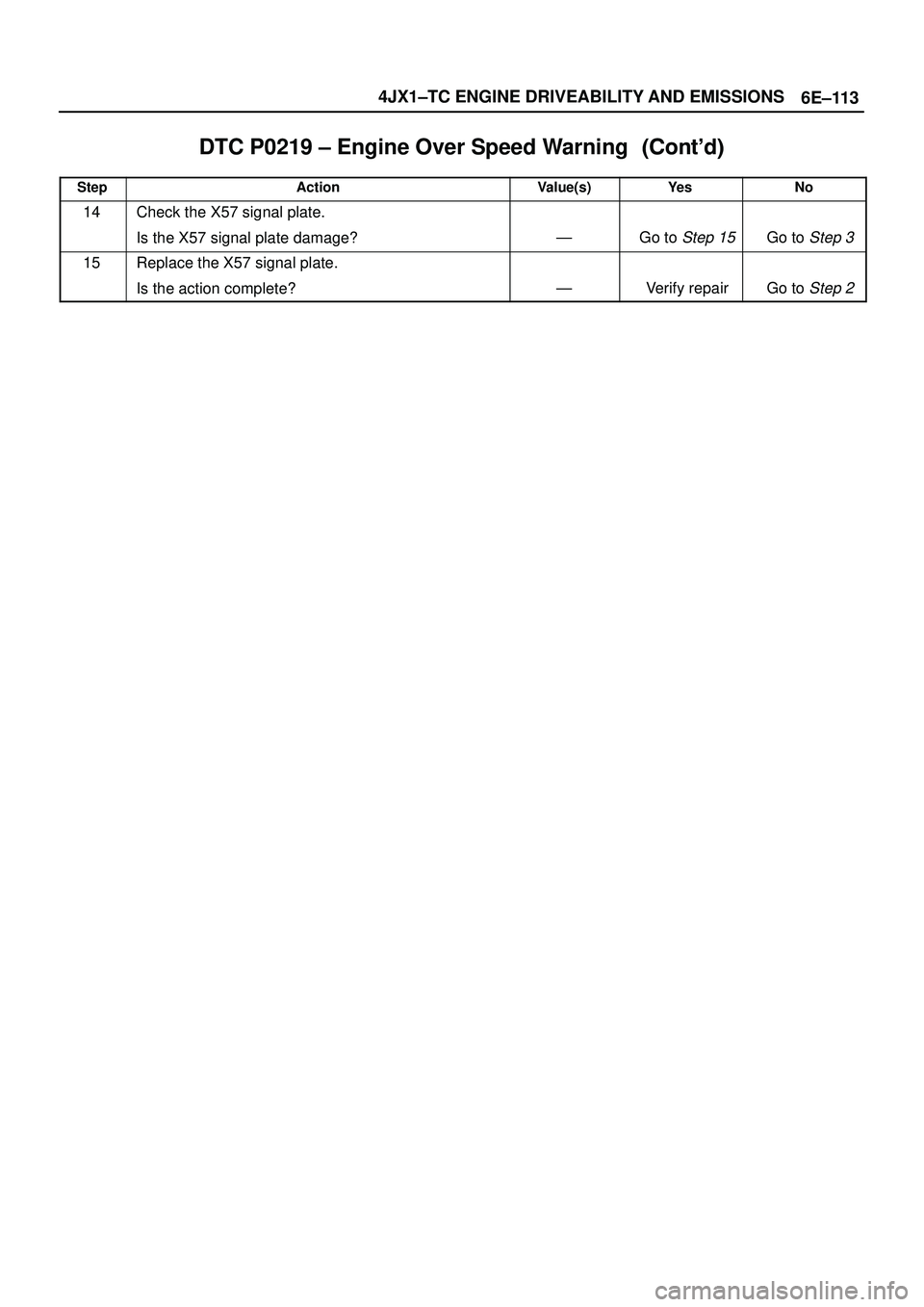
6E±113 4JX1±TC ENGINE DRIVEABILITY AND EMISSIONS
DTC P0219 ± Engine Over Speed Warning������ ���
StepNo Ye s Value(s) Action
14Check the X57 signal plate.
Is the X57 signal plate damage?
ÐGo to Step 15Go to Step 3
15Replace the X57 signal plate.
Is the action complete?
ÐVerify repairGo to Step 2
Page 2157 of 3573

Service Precaution
WARNING: I F S O E Q U IPPED WITH A
SUPPLEMENTAL RESTRAINT SYSTEM (SRS),
REFER TO THE SRS COMPONENT AND WIRING
LOCATION VIEW IN ORDER TO DETER")
7A±3 AUTOMATIC TRANSMISSION (4L30±E)
Service Precaution
WARNING: I F S O E Q U IPPED WITH A
SUPPLEMENTAL RESTRAINT SYSTEM (SRS),
REFER TO THE SRS COMPONENT AND WIRING
LOCATION VIEW IN ORDER TO DETERMINE
WHETHER YOU ARE PERFORMING SERVICE ON OR
NEAR THE SRS COMPONENTS OR THE SRS
WIRING. WHEN YOU ARE PERFORMING SERVICE
ON OR NEAR THE SRS COMPONENTS OR THE SRS
WIRING, REFER TO THE SRS SERVICE
INFORMATION. FAILURE TO FOLLOW WARNINGS
COULD RESULT IN POSSIBLE AIR BAG
DEPLOYMENT, PERSONAL INJURY, OR
OTHERWISE UNNEEDED SRS SYSTEM REPAIRS.CAUTION: Always use the correct fastener in the
proper location. When you replace a fastener, use
ONLY the exact part number for that application.
ISUZU will call out those fasteners that require a
replacement after removal. ISUZU will also call out
the fasteners that require thread lockers or thread
sealant. UNLESS OTHERWISE SPECIFIED, do not
use supplemental coatings (Paints, greases, or other
corrosion inhibitors) on threaded fasteners or
fastener joint interfaces. Generally, such coatings
adversely affect the fastener torque and the joint
clamping force, and may damage the fastener. When
you install fasteners, use the correct tightening
sequence and specifications. Following these
instructions can help you avoid damage to parts and
systems.
Construction
A07RS001
Legend
(1) Torque Converter Clutch (TCC)
(2) Fourth Clutch (C4)
(3) Overrun Clutch (OC)
(4) Overdrive Unit
(5) Reverse Clutch (RC)
(6) Second Clutch (C2)(7) Third Clutch (C3)
(8) Ravigneaux Planetary Gear Set
(9) Brake Band (B)
(10) Overdrive Free Wheel (One Way Clutch)
(OFW)
(11) Sprag Free Wheel (One Way Clutch) (PFW)
 P1196 (Flash DTC 62)
Rail Pressure System High Warning
060RW178
Legend
(1) ECM
(2) Meter Panel
(3) Battery
(4) Oil Temp")