1998 ISUZU TROOPER check engine
[x] Cancel search: check enginePage 1533 of 3573
SERVICE INFORMATION 00 Ð 33
ENGINE CONTROL
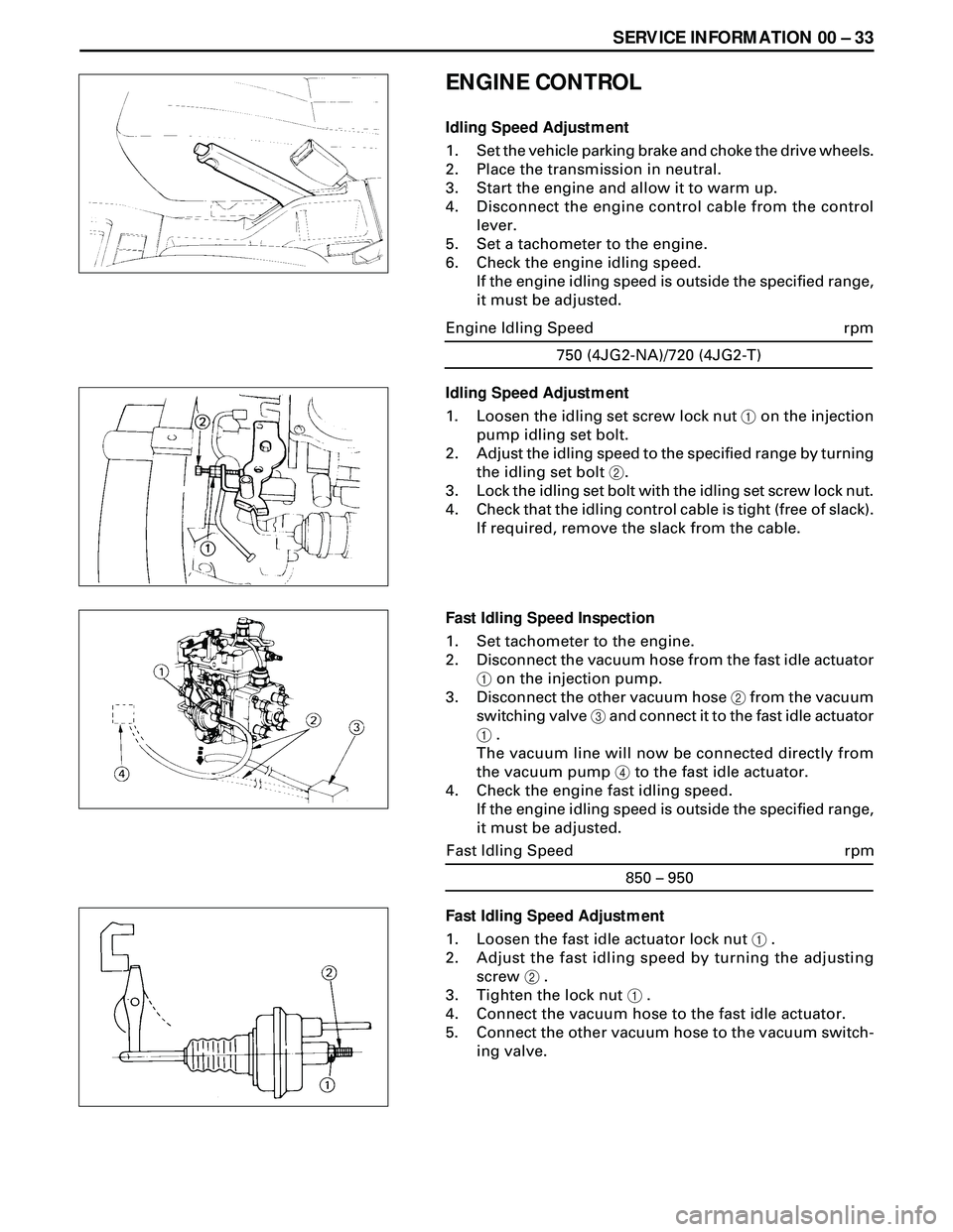
Idling Speed Adjustment
1. Set the vehicle parking brake and choke the drive wheels.
2. Place the transmission in neutral.
3. Start the engine and allow it to warm up.
4. Disconnect the engine control cable from the control
lever.
5. Set a tachometer to the engine.
6. Check the engine idling speed.
If the engine idling speed is outside the specified range,
it must be adjusted.
Fast Idling Speed Adjustment
1. Loosen the fast idle actuator lock nut 1 .
2. Adjust the fast idling speed by turning the adjusting
screw 2 .
3. Tighten the lock nut 1 .
4. Connect the vacuum hose to the fast idle actuator.
5. Connect the other vacuum hose to the vacuum switch-
ing valve.750 (4JG2-NA)/720 (4JG2-T)
rpm Engine Idling Speed
Idling Speed Adjustment
1. Loosen the idling set screw lock nut 1 on the injection
pump idling set bolt.
2. Adjust the idling speed to the specified range by turning
the idling set bolt 2.
3. Lock the idling set bolt with the idling set screw lock nut.
4. Check that the idling control cable is tight (free of slack).
If required, remove the slack from the cable.
Fast Idling Speed Inspection
1. Set tachometer to the engine.
2. Disconnect the vacuum hose from the fast idle actuator
1 on the injection pump.
3. Disconnect the other vacuum hose 2 from the vacuum
switching valve 3 and connect it to the fast idle actuator
1 .
The vacuum line will now be connected directly from
the vacuum pump 4 to the fast idle actuator.
4. Check the engine fast idling speed.
If the engine idling speed is outside the specified range,
it must be adjusted.
850 – 950
rpm Fast Idling Speed
Page 1534 of 3573
00 Ð 34 SERVICE INFORMATION
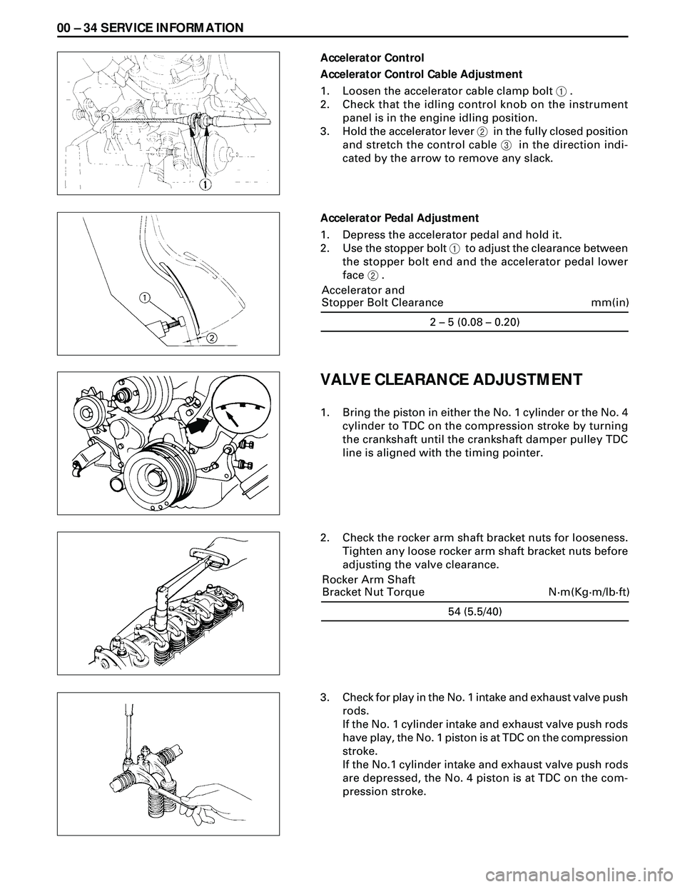
Accelerator Control
Accelerator Control Cable Adjustment
1. Loosen the accelerator cable clamp bolt 1 .
2. Check that the idling control knob on the instrument
panel is in the engine idling position.
3. Hold the accelerator lever 2 in the fully closed position
and stretch the control cable 3 in the direction indi-
cated by the arrow to remove any slack.
Accelerator Pedal Adjustment
1. Depress the accelerator pedal and hold it.
2. Use the stopper bolt 1 to adjust the clearance between
the stopper bolt end and the accelerator pedal lower
face 2 .
VALVE CLEARANCE ADJUSTMENT
1. Bring the piston in either the No. 1 cylinder or the No. 4
cylinder to TDC on the compression stroke by turning
the crankshaft until the crankshaft damper pulley TDC
line is aligned with the timing pointer.
2. Check the rocker arm shaft bracket nuts for looseness.
Tighten any loose rocker arm shaft bracket nuts before
adjusting the valve clearance.
3. Check for play in the No. 1 intake and exhaust valve push
rods.
If the No. 1 cylinder intake and exhaust valve push rods
have play, the No. 1 piston is at TDC on the compression
stroke.
If the No.1 cylinder intake and exhaust valve push rods
are depressed, the No. 4 piston is at TDC on the com-
pression stroke.
54 (5.5/40)
N·m(Kg·m/lb·ft) Rocker Arm Shaft
Bracket Nut Torque2 – 5 (0.08 – 0.20)
mm(in) Accelerator and
Stopper Bolt Clearance
Page 1560 of 3573
6A Ð 10 ENGINE MECHANICAL
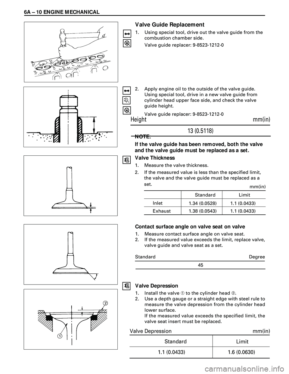
Valve Guide Replacement
1. Using special tool, drive out the valve guide from the
combustion chamber side.
Valve guide replacer: 9-8523-1212-0
2. Apply engine oil to the outside of the valve guide.
Using special tool, drive in a new valve guide from
cylinder head upper face side, and check the valve
guide height.
Valve guide replacer: 9-8523-1212-0
NOTE:
If the valve guide has been removed, both the valve
and the valve guide must be replaced as a set.
Valve Thickness
1. Measure the valve thickness.
2. If the measured value is less than the specified limit,
the valve and the valve guide must be replaced as a
set.
Contact surface angle on valve seat on valve
1. Measure contact surface angle on valve seat.
2. If the measured value exceeds the limit, replace valve,
valve guide and valve seat as a set.
mm(in)
13 (0.5118) Height
Standard
mm(in)
Limit
1.1 (0.0433)
1.6 (0.0630)
Valve Depression
Degree
45 Standard
Valve Depression
1. Install the valve À to the cylinder head Á.
2. Use a depth gauge or a straight edge with steel rule to
measure the valve depression from the cylinder head
lower surface.
If the measured value exceeds the specified limit, the
valve seat insert must be replaced.
Inletmm(in)1.1 (0.0433) Standard Limit
Exhaust1.34 (0.0528)
1.1 (0.0433) 1.38 (0.0543)
Page 1561 of 3573

ENGINE MECHANICAL 6A Ð 11
Valve Contact Width
1. Check the valve contact faces for roughness and
unevenness. Make smooth the valve contact sur-
faces.
2. Measure the valve contact width.
If the measured value exceeds the specified limit, the
valve seat insert must be replaced.
Valve Seat Insert Replacement
Valve Seat Insert Removal
1. Arc weld the entire inside circumference À of the
valve seat insert Á.
2. Allow the valve seat insert to cool for a few minutes.
This will invite contraction and make removal of the
valve seat insert easier.
3. Use a screwdriver  to pry the valve seat insert free.
Take care not to damage the cylinder head Ö .
4. Carefully remove carbon and other foreign material
from the cylinder head insert bore.
Valve Seat Insert Installation
1. Carefully place the attachment À (having a smaller
outside diameter than the valve seat insert) on the
valve seat insert Á .
Note:
The smooth side of the attachment must contact
the valve seat insert.
2. Use a bench press  to gradually apply pressure to
the attachment and press the valve seat insert into
place.
Note:
Do not apply an excessive amount of pressure with
the bench press. Damage to the valve seat insert
will result.
Valve Seat Insert Correction
1. Remove the carbon from the valve seat insert surface.
2. Use a valve cutter (15°, 45°, and 75° blades) to mini-
mize scratches and other rough areas. this will bring
the contact width back to the standard value.
Remove only the scratches and rough areas. Do not
cut away too much. Take care not to cut away un-
blemished areas of the valve seat surface.
Inlet
mm(in)
2.2 (0.0866)
Standard Limit
Exhaust1.7 (0.0669)
2.5 (0.0984) 2.0 (0.0787)
Page 1562 of 3573
6A Ð 12 ENGINE MECHANICAL
3. Visually inspect both ends of the push rod for exces-
sive wear and damage. The push rod must be re-
placed if these conditions are discovered during
inspection.
REASSEMBLY
6. Valve Guide
·Apply engine oil to the outside of the valve guide.
Using special tool, drive in a new valve guide from
the cmashft side.
Valve guide replacer: 9-8523-1212-0
5. Valve Stem Oil Seal
·Using special tool, drive in a new oil seal
Oil special tool, drive in anew oil seal
Oil seal installer: 5-8840-2033-0
4. Valve
·Apply engine oil to the outside of the valve stem.
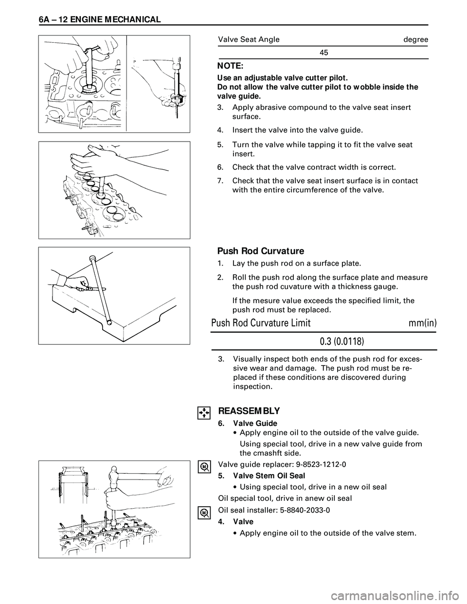
Push Rod Curvature
1. Lay the push rod on a surface plate.
2. Roll the push rod along the surface plate and measure
the push rod cuvature with a thickness gauge.
If the mesure value exceeds the specified limit, the
push rod must be replaced.
NOTE:
Use an adjustable valve cutter pilot.
Do not allow the valve cutter pilot to wobble inside the
valve guide.
3. Apply abrasive compound to the valve seat insert
surface.
4. Insert the valve into the valve guide.
5. Turn the valve while tapping it to fit the valve seat
insert.
6. Check that the valve contract width is correct.
7. Check that the valve seat insert surface is in contact
with the entire circumference of the valve.
mm(in)
0.3 (0.0118) Push Rod Curvature Limit
degree
45 Valve Seat Angle
Page 1570 of 3573
6A Ð 20 ENGINE MECHANICAL
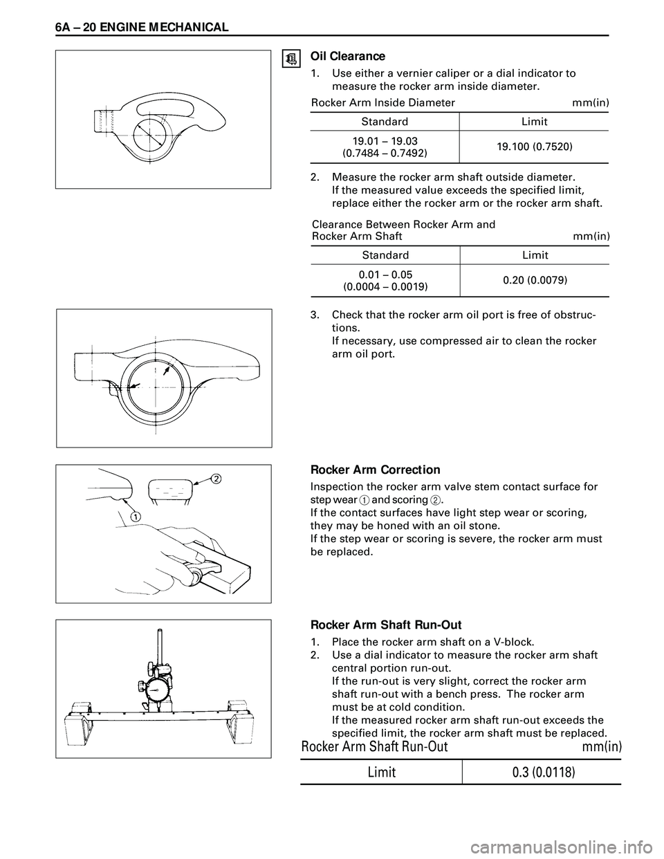
Oil Clearance
1. Use either a vernier caliper or a dial indicator to
measure the rocker arm inside diameter.
2. Measure the rocker arm shaft outside diameter.
If the measured value exceeds the specified limit,
replace either the rocker arm or the rocker arm shaft.
3. Check that the rocker arm oil port is free of obstruc-
tions.
If necessary, use compressed air to clean the rocker
arm oil port.
Rocker Arm Correction
Inspection the rocker arm valve stem contact surface for
step wear 1 and scoring 2.
If the contact surfaces have light step wear or scoring,
they may be honed with an oil stone.
If the step wear or scoring is severe, the rocker arm must
be replaced.
Rocker Arm Shaft Run-Out
1. Place the rocker arm shaft on a V-block.
2. Use a dial indicator to measure the rocker arm shaft
central portion run-out.
If the run-out is very slight, correct the rocker arm
shaft run-out with a bench press. The rocker arm
must be at cold condition.
If the measured rocker arm shaft run-out exceeds the
specified limit, the rocker arm shaft must be replaced.
0.3 (0.0118)
mm(in) Rocker Arm Shaft Run-Out
Limit
Standard Limit
mm(in)
19.01 – 19.03
(0.7484 – 0.7492)19.100 (0.7520) Rocker Arm Inside Diameter
Standard Limit
mm(in)
0.01 – 0.05
(0.0004 – 0.0019)0.20 (0.0079) Clearance Between Rocker Arm and
Rocker Arm Shaft
Page 1576 of 3573
6A Ð 26 ENGINE MECHANICAL
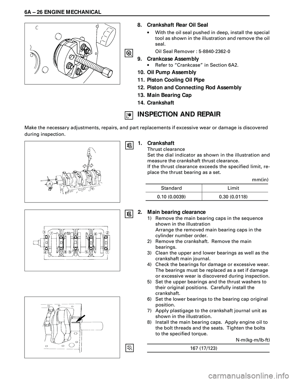
8. Crankshaft Rear Oil Seal
·With the oil seal pushed in deep, install the special
tool as shown in the illustration and remove the oil
seal.
Oil Seal Remover : 5-8840-2362-0
9. Crankcase Assembly
·Refer to ÒCrankcaseÓ in Section 6A2.
10. Oil Pump Assembly
11. Piston Cooling Oil Pipe
12. Piston and Connecting Rod Assembly
13. Main Bearing Cap
14. Crankshaft
INSPECTION AND REPAIR
Make the necessary adjustments, repairs, and part replacements if excessive wear or damage is discovered
during inspection.
1. Crankshaft
Thrust clearance
Set the dial indicator as shown in the illustration and
measure the crankshaft thrust clearance.
If the thrust clearance exceeds the specified limit, re-
place the thrust bearing as a set.
Standard Limit
mm(in)
0.10 (0.0039) 0.30 (0.0118)
167 (17/123)N·m(kg·m/lb·ft)
2. Main bearing clearance
1) Remove the main bearing caps in the sequence
shown in the illustration
Arrange the removed main bearing caps in the
cylinder number order.
2) Remove the crankshaft. Remove the main
bearings.
3) Clean the upper and lower bearings as well as the
crankshaft main journal.
4) Check the bearings for damage or excessive wear.
The bearings must be replaced as a set if damage
or excessive wear is discovered during inspection.
5) Set the upper bearings and the thrust washers to
their original positions. Carefully install the
crankshaft.
6) Set the lower bearings to the bearing cap original
position.
7) Apply plastigage to the crankshaft journal unit as
shown in the illustration.
8) Install the main bearing caps. Apply engine oil to
the bolt threads and the seats. Tighten the bolts
to the specified torque.
Page 1581 of 3573
ENGINE MECHANICAL 6A Ð 31
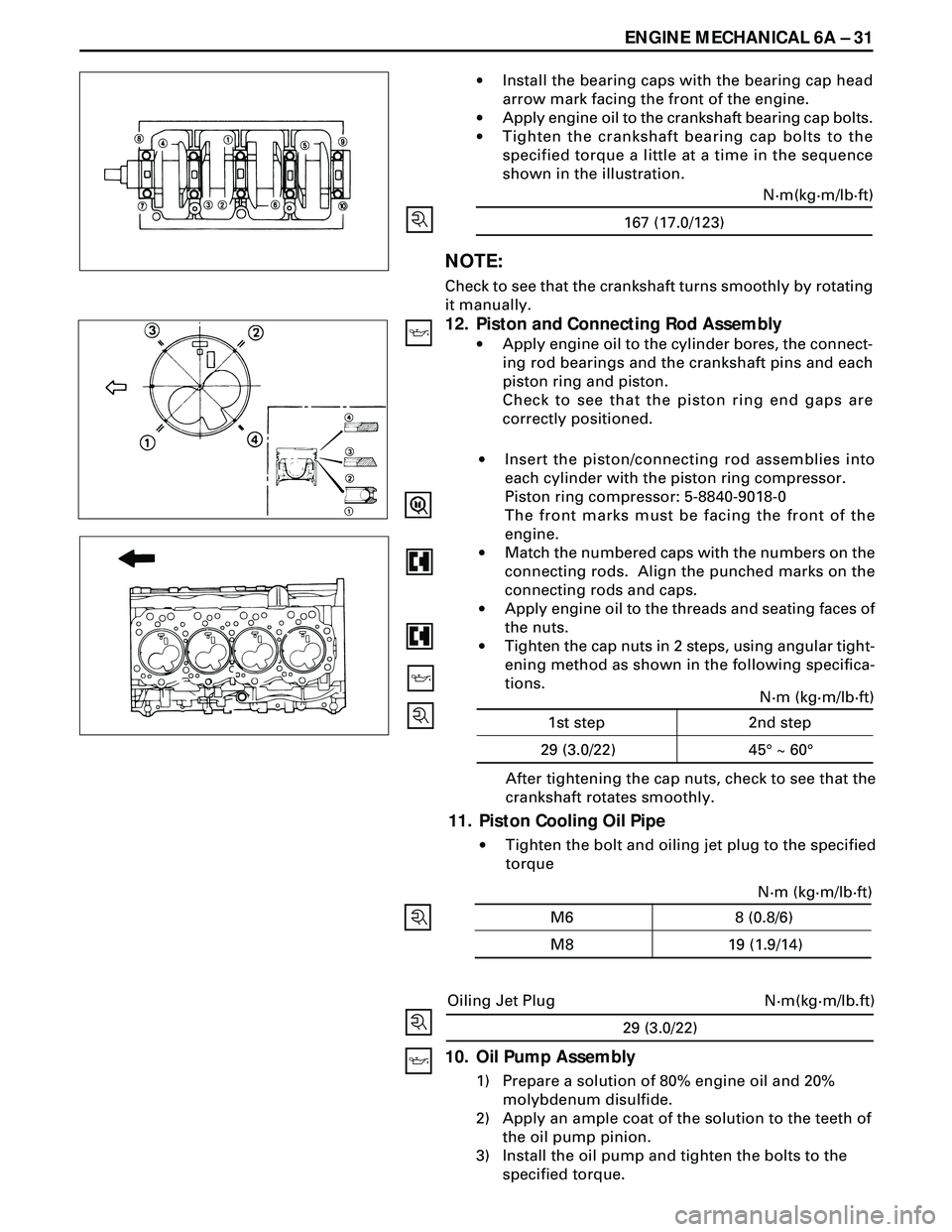
·Install the bearing caps with the bearing cap head
arrow mark facing the front of the engine.
·Apply engine oil to the crankshaft bearing cap bolts.
·Tighten the crankshaft bearing cap bolts to the
specified torque a little at a time in the sequence
shown in the illustration.
NOTE:
Check to see that the crankshaft turns smoothly by rotating
it manually.
12. Piston and Connecting Rod Assembly
·Apply engine oil to the cylinder bores, the connect-
ing rod bearings and the crankshaft pins and each
piston ring and piston.
Check to see that the piston ring end gaps are
correctly positioned.
29 (3.0/22)
N·m(kg·m/lb.ft) Oiling Jet Plug
10. Oil Pump Assembly
1) Prepare a solution of 80% engine oil and 20%
molybdenum disulfide.
2) Apply an ample coat of the solution to the teeth of
the oil pump pinion.
3) Install the oil pump and tighten the bolts to the
specified torque.After tightening the cap nuts, check to see that the
crankshaft rotates smoothly.
11. Piston Cooling Oil Pipe
·Tighten the bolt and oiling jet plug to the specified
torque ·Insert the piston/connecting rod assemblies into
each cylinder with the piston ring compressor.
Piston ring compressor: 5-8840-9018-0
The front marks must be facing the front of the
engine.
·Match the numbered caps with the numbers on the
connecting rods. Align the punched marks on the
connecting rods and caps.
·Apply engine oil to the threads and seating faces of
the nuts.
·Tighten the cap nuts in 2 steps, using angular tight-
ening method as shown in the following specifica-
tions.
167 (17.0/123)N·m(kg·m/lb·ft)
N·m (kg·m/lb·ft)
45¡ ~ 60¡ 1st step 2nd step
29 (3.0/22)
N·m (kg·m/lb·ft)
19 (1.9/14) M6 8 (0.8/6)
M8