Page 1511 of 3573

SERVICE INFORMATION 00 Ð 11
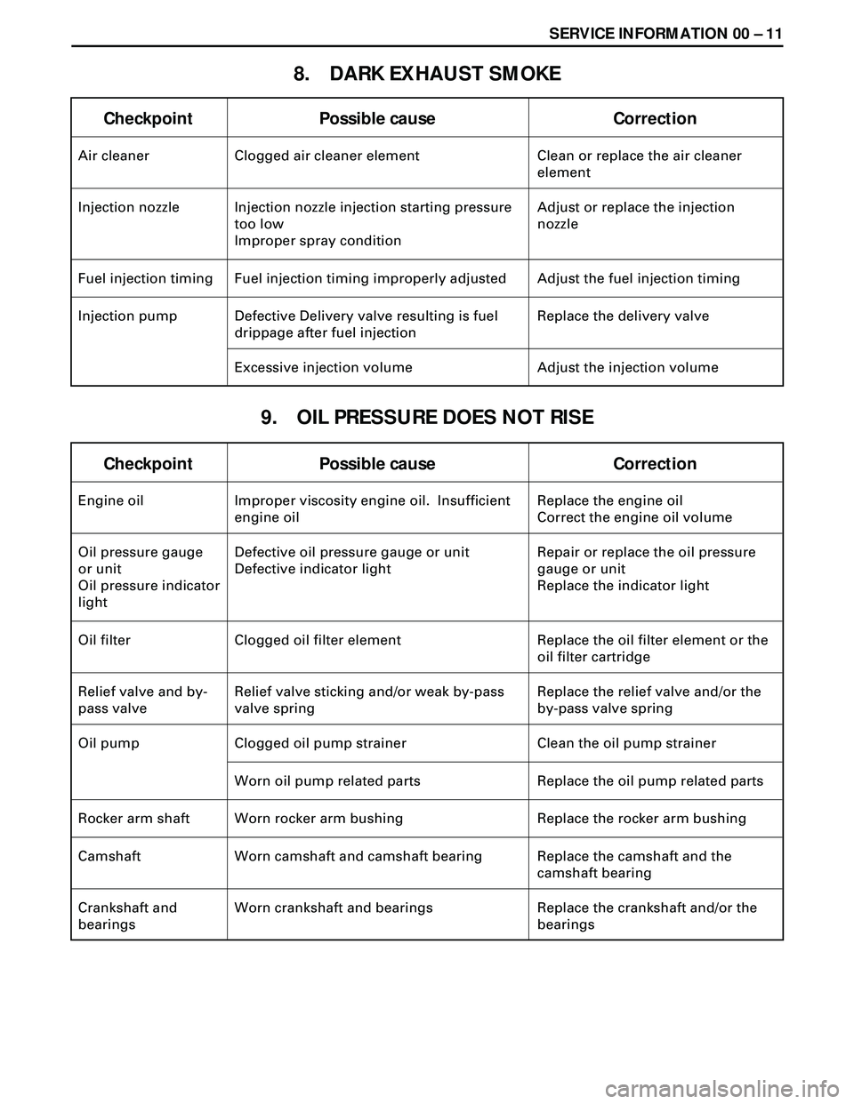
8. DARK EXHAUST SMOKE
Checkpoint Possible cause Correction
Air cleaner Clogged air cleaner element Clean or replace the air cleaner
element
Injection nozzle Injection nozzle injection starting pressure
too low
Improper spray conditionAdjust or replace the injection
nozzle
Fuel injection timing Fuel injection timing improperly adjusted Adjust the fuel injection timing
Injection pump Defective Delivery valve resulting is fuel
drippage after fuel injectionReplace the delivery valve
Excessive injection volume Adjust the injection volume
9. OIL PRESSURE DOES NOT RISE
Checkpoint Possible cause Correction
Engine oil Improper viscosity engine oil. Insufficient
engine oilReplace the engine oil
Correct the engine oil volume
Oil pressure gauge
or unit
Oil pressure indicator
lightDefective oil pressure gauge or unit
Defective indicator lightRepair or replace the oil pressure
gauge or unit
Replace the indicator light
Oil filter Clogged oil filter element Replace the oil filter element or the
oil filter cartridge
Relief valve and by-
pass valveRelief valve sticking and/or weak by-pass
valve springReplace the relief valve and/or the
by-pass valve spring
Oil pump Clogged oil pump strainer Clean the oil pump strainer
Worn oil pump related parts Replace the oil pump related parts
Rocker arm shaft Worn rocker arm bushing Replace the rocker arm bushing
Camshaft Worn camshaft and camshaft bearing Replace the camshaft and the
camshaft bearing
Crankshaft and
bearingsWorn crankshaft and bearings Replace the crankshaft and/or the
bearings
Page 1512 of 3573

00 Ð 12 SERVICE INFORMATION
10. ABNORMAL ENGINE NOISE
Checkpoint Possible cause Correction
Fuel Fuel unsuitable Replace the fuel
1. ENGINE KNOCKING
2. GAS LEAKAGE NOISE
Exhaust pipes Loosely connected exhaust pipes. Broken
exhaust pipesTighten the exhaust pipe
connections
Replace the exhaust pipes Check to see that the engine has been thoroughly warmed up before begining the troubleshooting
procedure.
Fuel injection timing Fuel injection timing improperly adjusted Adjust the fuel injection timing
Injection nozzle Improper injection nozzle starting pressure
and spray conditionAdjust or replace the injection
nozzle
Compression
pressureBlown out head gasket
Broken piston ringReplace the head gasket or the
piston ring
Injection nozzles
and/or glow plugsLoose injection nozzles and/or glow plugs Replace the washers
Tighten the injection nozzles and/or
the glow plugs
Exhaust manifold Loosely connected exhaust manifold and/or
glow plugsTighten the exhaust manifold
connections
Cylinder head gasket Damaged cylinder head gasket Replace the cylinder head gasket
3. CONTINUOUS NOISE
Fan belt Loose fan belt Readjust the fan belt tension
Cooling fan Loose coling fan Retighten the cooling fan
Water pump bearing Worn or damaged water pump bearing Replace the water pump bearing
Alternator or vacuum
pumpDefective alternator or vacuum pump Repair or replace the alternator or
the vacuum pump
Valve clearance Clearance improperly adjust Adjust the valve clearance
Page 1515 of 3573
SERVICE INFORMATION 00 Ð 15
ENGINE ELECTRICAL
Check if the battery is normal, then perform the following diagnosis.
STARTER DOES NOT RUN
CHECK BATTERY
CHARGING FAILURE OR LIFE
CHECK BATTERY
BATTERY IS NORMAL
CHECK TERMINAL CONNECTION
CONNECTION FAILURE
CLEAN BATTERY TERMINALS, AND RECONNECT
TERMINAL CONNECTION IS NORMAL
CHECK STARTER OR STARTER SWITCH
FAILURE
REPAIR OR REPLACE
TURN ON HEAD LAMP AND STARTER SWITCH
HEAD LAMP DOES NOT COME ON
OR IT IS EXTREMELY DARK
a) LACK OF BATTERY CHARGING
b) SHORT-CIRCUIT IN STARTER COIL
c) FAULTY STARTER PARTS
HEAD LAMP ILLUMINATES
a) DISCONNECTED STARTER CIRCUIT
b) DISCONNECTED STARTER COIL
c) FAULTY STARTER SWITCH
Page 1518 of 3573
00 Ð 18 SERVICE INFORMATION
PINION MESHES WITH RING GEAR BUT
ENGINE DOES NOT RUN
CHECK GROUND CABLE
YESNO
REPAIR OR REPLACE
GROUND CABLE
FAULTY CONNECTION
OF BRUSH AND
COMMUTATORBURNED-OUT
MAGNETIC
STARTER SWITCHDISCONNECTION
OR DAMAGE OF
FIELD COILDISCONNECTION
OR DAMAGE OF
ARMATURE COILSLIP OF
PINION
CLUTCH
REPAIR OR REPLACE STARTER
Page 1528 of 3573

00 Ð 28 SERVICE INFORMATION
3. Remove the element from the solution and rinse it well
with running water.
Water pressure must not exceed 274 Kpa (2.8 kg/cm
2/40
Psi)
4. Dry the element in a well ventilated area.
An electric fan will hasten drying.
NOTE:
Do not use compressed air or an open flame to dry the
element quickly. Damage to the element will result.
It will usually take two or three days for the element to dry
completely. Therefore, it is a good idea to have a spare on
hand to use in the interim.
LUBRICATING SYSTEM
Main Oil Filter (Cartridge Type Paper Element)
Replacement Procedure
1. Loosen the drain plug to drain the engine oil.
2. Wait a few minutes and then retighten the drain plug.
3. Loosen the used oil filter by turning it counterclockwise
with the filter wrench.
4. Clean the oil cooler fitting face.
This will allow the new oil filter to seat properly.
5. Apply a light coat of engine oil to the O-ring.
6. Turn in the new oil filter until the filter O-ring is fitted
against the sealing face.
7. Use the filter wrench to turn in the filter an additional 1
and 1/4 turns.
Filter Wrench: 5-8840-0200-0
8. Check the engine oil level and replenish to the specified
level if required.
0.7 (0.62/0.74)
lit(Imp qt / US qt) Replenishment Engine Oil
9. Start the engine and check for oil leakage from the main
oil filter.
Page 1529 of 3573

SERVICE INFORMATION 00 Ð 29
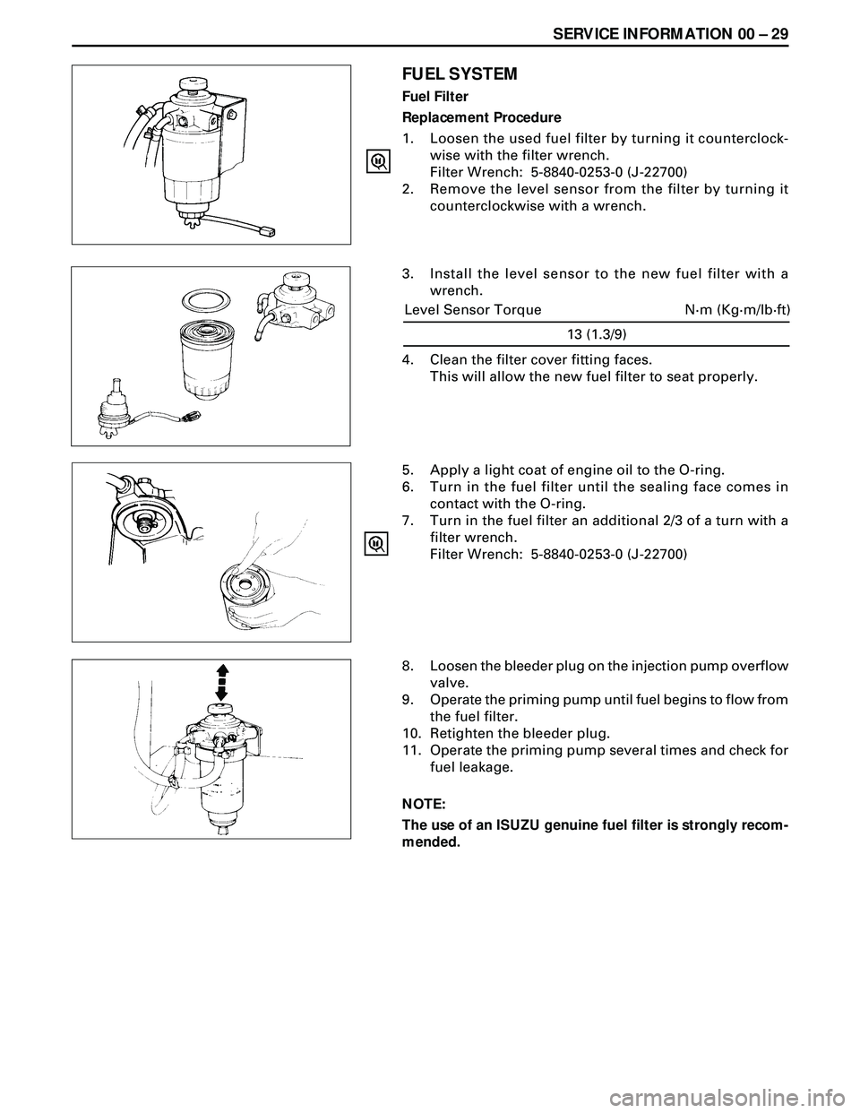
FUEL SYSTEM
Fuel Filter
Replacement Procedure
1. Loosen the used fuel filter by turning it counterclock-
wise with the filter wrench.
Filter Wrench: 5-8840-0253-0 (J-22700)
2. Remove the level sensor from the filter by turning it
counterclockwise with a wrench.
3. Install the level sensor to the new fuel filter with a
wrench.
5. Apply a light coat of engine oil to the O-ring.
6. Turn in the fuel filter until the sealing face comes in
contact with the O-ring.
7. Turn in the fuel filter an additional 2/3 of a turn with a
filter wrench.
Filter Wrench: 5-8840-0253-0 (J-22700)
8. Loosen the bleeder plug on the injection pump overflow
valve.
9. Operate the priming pump until fuel begins to flow from
the fuel filter.
10. Retighten the bleeder plug.
11. Operate the priming pump several times and check for
fuel leakage.
NOTE:
The use of an ISUZU genuine fuel filter is strongly recom-
mended.
13 (1.3/9)
N·m (Kg·m/lb·ft) Level Sensor Torque
4. Clean the filter cover fitting faces.
This will allow the new fuel filter to seat properly.
Page 1530 of 3573

00 Ð 30 SERVICE INFORMATION
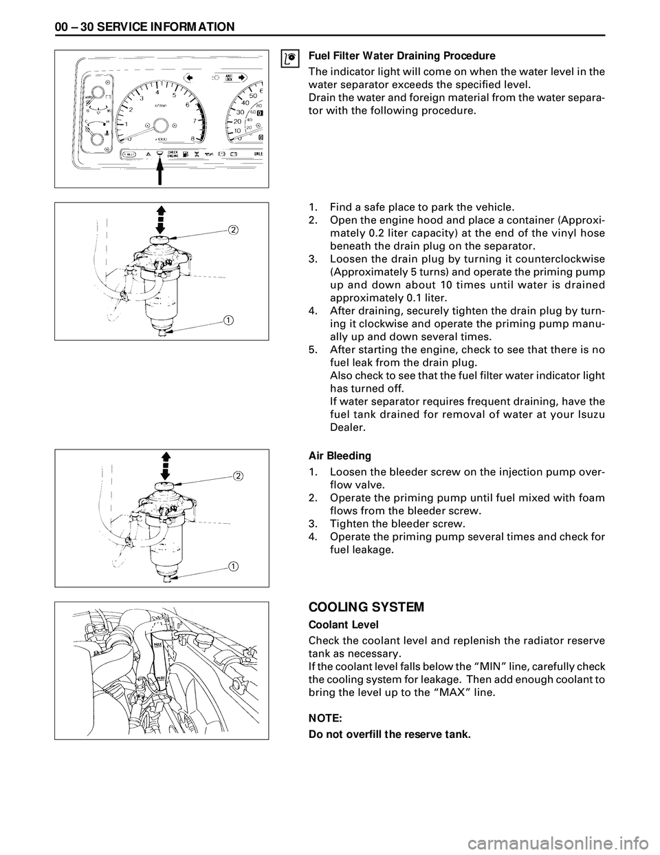
Fuel Filter Water Draining Procedure
The indicator light will come on when the water level in the
water separator exceeds the specified level.
Drain the water and foreign material from the water separa-
tor with the following procedure.
1. Find a safe place to park the vehicle.
2. Open the engine hood and place a container (Approxi-
mately 0.2 liter capacity) at the end of the vinyl hose
beneath the drain plug on the separator.
3. Loosen the drain plug by turning it counterclockwise
(Approximately 5 turns) and operate the priming pump
up and down about 10 times until water is drained
approximately 0.1 liter.
4. After draining, securely tighten the drain plug by turn-
ing it clockwise and operate the priming pump manu-
ally up and down several times.
5. After starting the engine, check to see that there is no
fuel leak from the drain plug.
Also check to see that the fuel filter water indicator light
has turned off.
If water separator requires frequent draining, have the
fuel tank drained for removal of water at your Isuzu
Dealer.
Air Bleeding
1. Loosen the bleeder screw on the injection pump over-
flow valve.
2. Operate the priming pump until fuel mixed with foam
flows from the bleeder screw.
3. Tighten the bleeder screw.
4. Operate the priming pump several times and check for
fuel leakage.
COOLING SYSTEM
Coolant Level
Check the coolant level and replenish the radiator reserve
tank as necessary.
If the coolant level falls below the ÒMINÓ line, carefully check
the cooling system for leakage. Then add enough coolant to
bring the level up to the ÒMAXÓ line.
NOTE:
Do not overfill the reserve tank.
Page 1531 of 3573

SERVICE INFORMATION 00 Ð 31
Remove the radiator filler cap only when absolutely neces-
sary.
Always check the coolant level when the engine is cold.
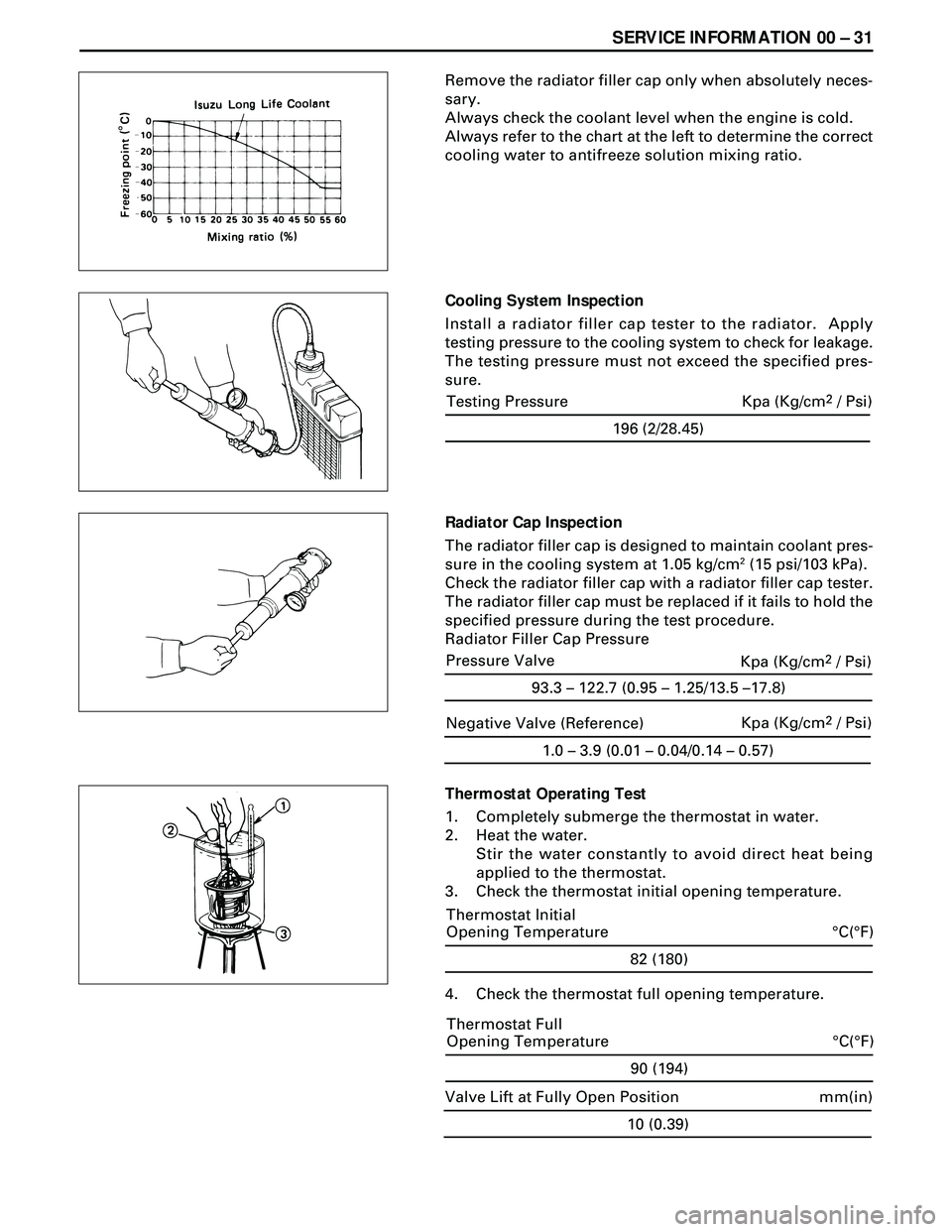
Always refer to the chart at the left to determine the correct
cooling water to antifreeze solution mixing ratio.
Cooling System Inspection
Install a radiator filler cap tester to the radiator. Apply
testing pressure to the cooling system to check for leakage.
The testing pressure must not exceed the specified pres-
sure.
Radiator Cap Inspection
The radiator filler cap is designed to maintain coolant pres-
sure in the cooling system at 1.05 kg/cm
2 (15 psi/103 kPa).
Check the radiator filler cap with a radiator filler cap tester.
The radiator filler cap must be replaced if it fails to hold the
specified pressure during the test procedure.
Radiator Filler Cap Pressure
Thermostat Operating Test
1. Completely submerge the thermostat in water.
2. Heat the water.
Stir the water constantly to avoid direct heat being
applied to the thermostat.
3. Check the thermostat initial opening temperature.
82 (180)
°C(°F) Thermostat Initial
Opening Temperature
4. Check the thermostat full opening temperature.
1.0 – 3.9 (0.01 – 0.04/0.14 – 0.57)
Negative Valve (Reference)Kpa (Kg/cm2 / Psi)
90 (194)
°C(°F) Thermostat Full
Opening Temperature
10 (0.39)
mm(in) Valve Lift at Fully Open Position
196 (2/28.45)
Testing Pressure Kpa (Kg/cm2 / Psi)
93.3 – 122.7 (0.95 – 1.25/13.5 –17.8)
Pressure Valve
Kpa (Kg/cm2 / Psi)