Page 1658 of 3573

6B Ð 4 ENGINE COOLING
ANTI-FREEZE SOLUTION
·Relation between Mixing ratio and Freezing point
Freezing temperature of the engine coolant varies
with the ratio of anti-freeze solution in water.
Proper mixing ratio can be determined by refering to
the chart. Supplemental inhibitors or additives
claiming to increase cooling capability that have not
been specifically approved by Isuzu are not
recommended for addition to the cooling system.
·Calculation of mixing ratio
Mixing ratio
Note: Anti-freeze solution + Water = 8.6 lit
Total cooling system capacity.
=Anti-freeze solution (Lit/qt.)
Anti-freeze solution (Lit/
qt.) + Water (Lit/qt.)
In case of 6.8 lit total cooling system capacity
Mixing
ratio (%)Anti-freeze
solution:
lit. (imp. qt./U.S. qt)Water:
lit. (imp.qt/U.S. qt)
0
5
10
15
20
25
30
35
40
45
500
0.3
0.7
1.0
1.4
1.7
2.0
2.4
2.7
3.1
3.40
(0.26/0.32)
(0.62/0.74)
(0.88/0.93)
(1.23/1.48 )
(1.50/1.80)
(1.76/1.86)
(2.11/2.23)
(2.38/2.85)
(2.72/2.87)
(2.99/3.60)6.8
6.5
6.0
5.8
5.4
5.1
4.8
4.4
4.1
3.7
3.4
(5.98/7.19)
(5.71/6.87)
(5.28/6.34)
( 5.1/6.13)
( 4.75/5.7)
(4.49/5.39)
(4.22/5.04)
(3.87/4.65)
( 3.6/4.33)
(3.26/3.91)
(2.99/3.59)
·Mixing ratio
Check the specific gravity of engine coolant in the
cooling system in temperature ranges from 0¡ C to
50¡ C using a suction type hydrometer, then
determine the density of the coolant by refering to the
table at left.
Page 1662 of 3573
6B Ð 8 ENGINE COOLING
·Make sure that secondary valve opens fully at the
specified temperature.
Make necessary repair and parts replacement if extreme
wear or damage is found during inspection.
INSTALLATION
4. Thermostat
3. Gasket
2. Outlet Pipe
·Connect outlet pipe and tighten bolts to the
specified torque.
19(1.9/14)
N·m (Kgm/lb·ft)
1. Water Hose: Turbocharger (4JG2-T Only)
·Install battery ground cable.
·Pour coolant,
·Start the engine and check coolant leakage.
95 (203)
°C (°F) Valve Full Open Temperature
Page 1663 of 3573
ENGINE COOLING 6B Ð 9
RADIATOR
REMOVAL
Preparation
·Disconnect battery ground cable.
·Loosen drain plug to drain coolant.
1. Radiator Hose
·Disconnect lower hose and upper hose from the
engine.
2. Fan Guide Lower
·Remove clips on both sides and the bottom lock.
3. Reservoir Tank Hose
·Disconnect the hose from radiator.
4. Bracket
5. Radiator Assembly
·Remove upward the radiator assembly with hose,
taking care not to damage the radiator core by fan
blade.
·Remove cushion rubbers on both sides of the
bottom.
INSPECTION
Radiator Cap
·Measure the valve opening pressure with the radiator
cap tester. Replace the radiator cap if it exceeds the
standard.
Check the condition of negative pressure valve in the
center of valve seat side of the cap. If the valve seat
does not move smoothly due to rust or dust, clean or
replace the radiator cap.
Valve opening pressure
93.3 – 122.7 (0.95 – 1.25/13.5 – 17.8)kPa(Kg/cm2 / psi)
Page 1664 of 3573

6B Ð 10 ENGINE COOLING
Radiator Core
·Deformed radiator fins could reduce radiation effects,
resulting in overheat. Straighten the fins. In such a
case, take care not to damage the fin roots.
·Remove dust and other foreign materials.
Flushing the Radiator
·Wash the inside of radiator and the coolant passage
with water and neutral detergent. Remove all scales
and rust.
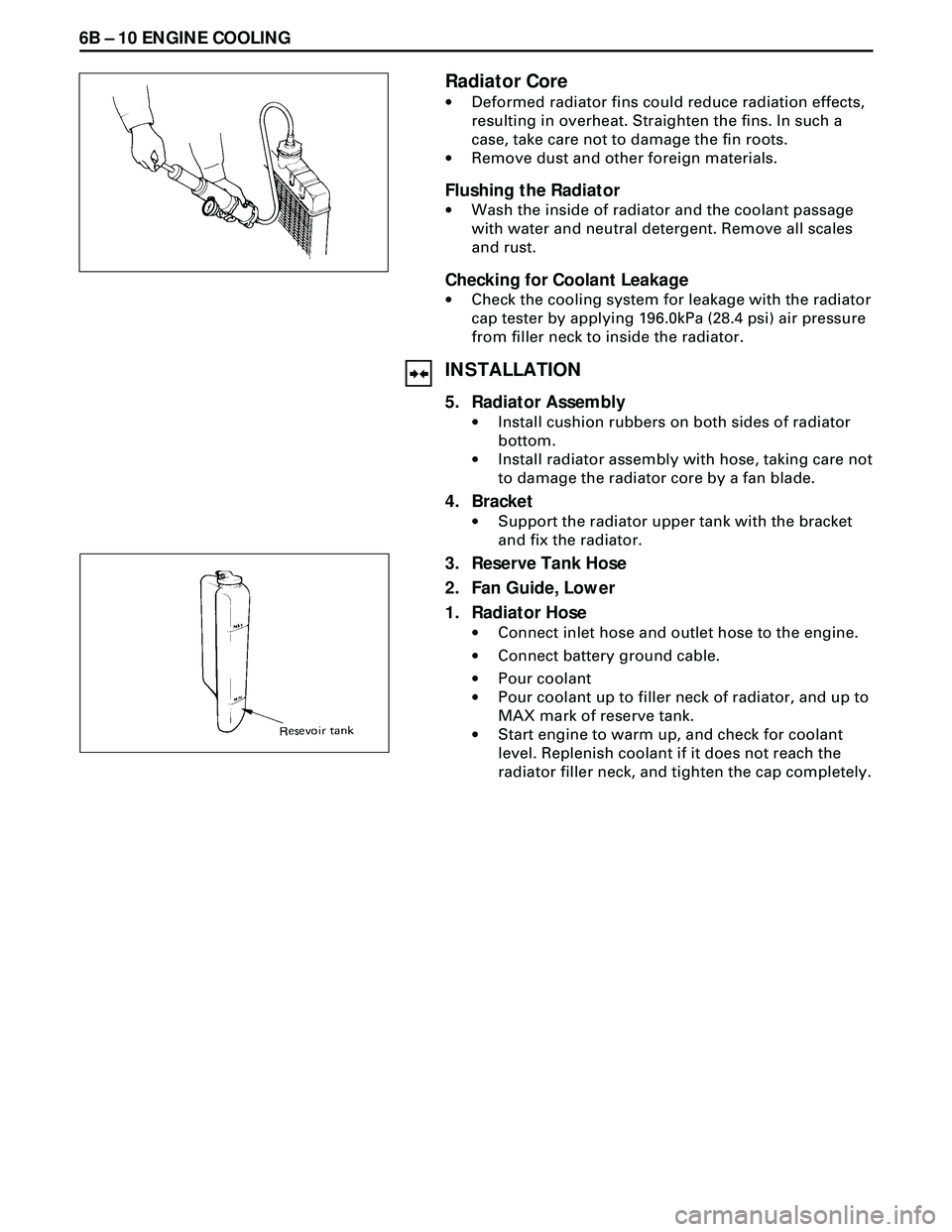
Checking for Coolant Leakage
·Check the cooling system for leakage with the radiator
cap tester by applying 196.0kPa (28.4 psi) air pressure
from filler neck to inside the radiator.
INSTALLATION
5. Radiator Assembly
·Install cushion rubbers on both sides of radiator
bottom.
·Install radiator assembly with hose, taking care not
to damage the radiator core by a fan blade.
4. Bracket
·Support the radiator upper tank with the bracket
and fix the radiator.
3. Reserve Tank Hose
2. Fan Guide, Lower
1. Radiator Hose
·Connect inlet hose and outlet hose to the engine.
·Connect battery ground cable.
·Pour coolant
·Pour coolant up to filler neck of radiator, and up to
MAX mark of reserve tank.
·Start engine to warm up, and check for coolant
level. Replenish coolant if it does not reach the
radiator filler neck, and tighten the cap completely.
Page 1665 of 3573
ENGINE COOLING 6B Ð 11
DRIVE BELT ADJUSTMENT
INSPECTION
Check drive belts for wear or damage, and replace with
new ones as necessary. Check belts for tension, and
adjust as necessary.
·Check drive belts tension
·Push the middle of belts with a force of 98 N (10 kg/22
lb) and check each bolt for deflection.
·Standard deflection
AC generator & fan pulley
drive beltInitial
tensionTension at
readjustment8~12 (0.31~0.47)
A/C compressor drive belt7~12
(0.28~0.39)5~8
(0.20~0.31)
mm (in)
P/S pump drive belt
13~16 (0.51~0.63)
Page 1674 of 3573

6C Ð 8 FUEL SYSTEM
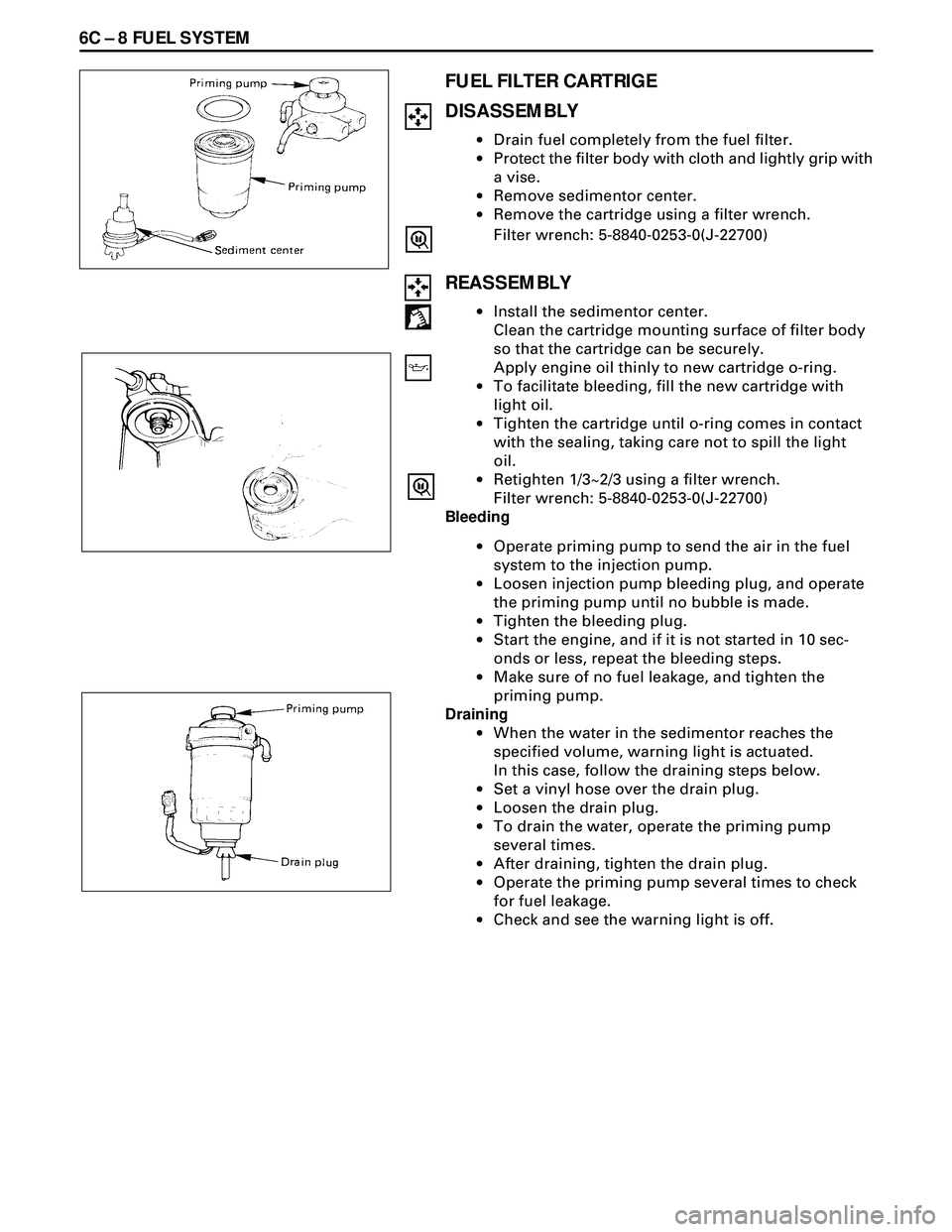
FUEL FILTER CARTRIGE
DISASSEMBLY
·Drain fuel completely from the fuel filter.
·Protect the filter body with cloth and lightly grip with
a vise.
·Remove sedimentor center.
·Remove the cartridge using a filter wrench.
Filter wrench: 5-8840-0253-0(J-22700)
REASSEMBLY
·Install the sedimentor center.
Clean the cartridge mounting surface of filter body
so that the cartridge can be securely.
Apply engine oil thinly to new cartridge o-ring.
·To facilitate bleeding, fill the new cartridge with
light oil.
·Tighten the cartridge until o-ring comes in contact
with the sealing, taking care not to spill the light
oil.
·Retighten 1/3~2/3 using a filter wrench.
Filter wrench: 5-8840-0253-0(J-22700)
Bleeding
·Operate priming pump to send the air in the fuel
system to the injection pump.
·Loosen injection pump bleeding plug, and operate
the priming pump until no bubble is made.
·Tighten the bleeding plug.
·Start the engine, and if it is not started in 10 sec-
onds or less, repeat the bleeding steps.
·Make sure of no fuel leakage, and tighten the
priming pump.
Draining
·When the water in the sedimentor reaches the
specified volume, warning light is actuated.
In this case, follow the draining steps below.
·Set a vinyI hose over the drain plug.
·Loosen the drain plug.
·To drain the water, operate the priming pump
several times.
·After draining, tighten the drain plug.
·Operate the priming pump several times to check
for fuel leakage.
·Check and see the warning light is off.
Page 1691 of 3573

ENGINE ELECTRICAL 6D1 Ð 1
SECTION 6D
ENGINE ELECTRICAL
CONTENTS
Battery................................................................................................................................... Section 6D1
Starting System ................................................................................................................... Section 6D2
Charging System.................................................................................................................. Section 6D3
QOS-IIIPreheating System ................................................................................................. Section 6D6
SECTION 6D1
BATTERY
CONTENTS
General Description ......................................... 6D1Ð1
Diagnosis .......................................................... 6D1Ð1
On-Vehicle Service........................................... 6D1Ð3
Battery Charging .......................................... 6D1Ð3Jump Starting .............................................. 6D1Ð3
Removal and Installation of Battery .......... 6D1Ð4
GENERAL DESCRIPTION
There are six battery fluid caps at the top of the
battery. These are covered by a paper label.
The battery is completely sealed except for the six
small vent holes at the side. These vent holes per-
mit the escape of small amounts of gas generated
by the battery.
This type of battery has the following advantages
over conventional batteries:1. There is no need to add water during the entire
service life of the battery.
2. The battery protects itself against overcharging.
The battery will refuse to accept an excessive
charge.
(A conventional battery will accept an excessive
charge, resulting in gassing and loss of battery
fluid.)
3. The battery is much less vulnerable to self-
discharge than a conventional type battery.
DIAGNOSIS
1. VISUAL INSPECTION
Inspect the battery for obvious physical damage,
such as a cracked or broken case, which would
permit electrolyte loss.
Replace the battery if obvious physical damage is
discovered during inspection.
Check for any other physical damage and correct it
as necessary. If not, proceed to Step 2.
2. HYDROMETER CHECK
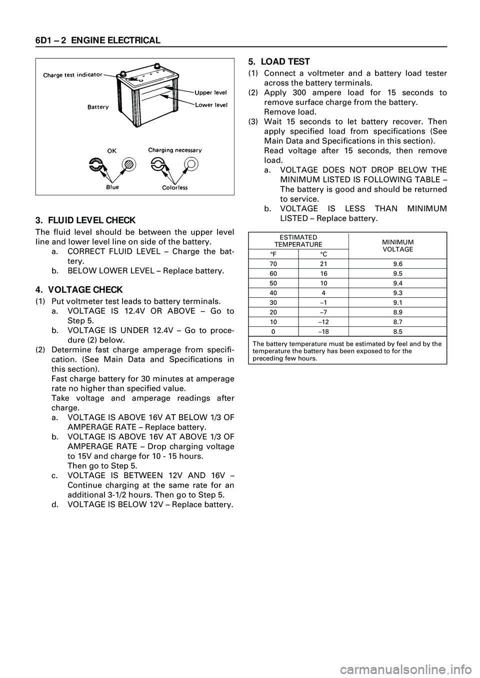
There is a built-in hydrometer (Charge test indica-
tor) at the top of the battery. It is designed to be
used during diagnostic procedures.Before trying to read the hydrometer, carefully
clean the upper battery surface.
If your work area is poorly lit, additional light may
be necessary to read the hydrometer.
a. BLUE RING OR DOT VISIBLE Ð Go to Step
4.
b. BLUE RING OR DOT NOT VISIBLE Ð Go to
Step 3.
Page 1692 of 3573

6D1 Ð 2 ENGINE ELECTRICAL
3. FLUID LEVEL CHECK
The fluid level should be between the upper level
line and lower level line on side of the battery.
a. CORRECT FLUID LEVEL Ð Charge the bat-
tery.
b. BELOW LOWER LEVEL Ð Replace battery.
4. VOLTAGE CHECK
(1) Put voltmeter test leads to battery terminals.
a. VOLTAGE IS 12.4V OR ABOVE Ð Go to
Step 5.
b. VOLTAGE IS UNDER 12.4V Ð Go to proce-
dure (2) below.
(2) Determine fast charge amperage from specifi-
cation. (See Main Data and Specifications in
this section).
Fast charge battery for 30 minutes at amperage
rate no higher than specified value.
Take voltage and amperage readings after
charge.
a. VOLTAGE IS ABOVE 16V AT BELOW 1/3 OF
AMPERAGE RATE Ð Replace battery.
b. VOLTAGE IS ABOVE 16V AT ABOVE 1/3 OF
AMPERAGE RATE Ð Drop charging voltage
to 15V and charge for 10 - 15 hours.
Then go to Step 5.
c. VOLTAGE IS BETWEEN 12V AND 16V Ð
Continue charging at the same rate for an
additional 3-1/2 hours. Then go to Step 5.
d. VOLTAGE IS BELOW 12V Ð Replace battery.
5. LOAD TEST
(1) Connect a voltmeter and a battery load tester
across the battery terminals.
(2) Apply 300 ampere load for 15 seconds to
remove surface charge from the battery.
Remove load.
(3) Wait 15 seconds to let battery recover. Then
apply specified load from specifications (See
Main Data and Specifications in this section).
Read voltage after 15 seconds, then remove
load.
a. VOLTAGE DOES NOT DROP BELOW THE
MINIMUM LISTED IS FOLLOWING TABLE Ð
The battery is good and should be returned
to service.
b. VOLTAGE IS LESS THAN MINIMUM
LISTED Ð Replace battery.
ESTIMATED
MINIMUM
TEMPERATURE
VOLTAGE
¡F ¡C
70 21 9.6
60 16 9.5
50 10 9.4
40 4 9.3
30 Ð1 9.1
20 Ð7 8.9
10 Ð12 8.7
0 Ð18 8.5
The battery temperature must be estimated by feel and by the
temperature the battery has been exposed to for the
preceding few hours.