Page 2019 of 3573
6E±126
4JX1±TC ENGINE DRIVEABILITY AND EMISSIONS
Diagnostic Trouble Code (DTC) P0380 (Flash DTC 66)
Glow Relay Circuit Open/Short
060RW132
Circuit Description
Glow relay circuit receives current through Glow 50A fuse
from the battery. Glow relay is circuited to Glow plug.
Action Taken When the DTC Sets
�The ECM will store conditions which were present
when the DTC was set as Freeze Frame and in the
Failure Records data.
Conditions for Clearing the MIL/DTC
�DTC P0380 can be cleared by using the Tech 2 ªClear
Infoº function or by disconnecting the ECM battery
feed.
Diagnostic Aids
An intermittent may be caused by a poor connection,
rubbed-through wire insulation or a wire broken inside the
insulation. Check for:
�Poor connection ± Inspect the ECM harness and
connectors for improper mating, broken locks,
improperly formed or damaged terminals, and poor
terminal-to-wire connection.
�Damaged harness ± Inspect the wiring harness for
damage.
Page 2020 of 3573
Ye sNo
1Was the ªOn-Board Diagnostic (OBD) System Checkº
performed?
ÐGo to Step 2
Go")
6E±127 4JX1±TC ENGINE DRIVEABILITY AND EMISSIONS
DTC P0380 ± Glow Relay Circuit Open/Short�
StepActionValue(s)Ye sNo
1Was the ªOn-Board Diagnostic (OBD) System Checkº
performed?
ÐGo to Step 2
Go to OBD
System
Check
2Attempt to start the engine.
Does the engine start?
ÐGo to Step 3Go to Chart 3
31. Review and record Failure Records information.
2. Clear DTC P0380.
3. Start the engine and idle for 1 minute.
4. Observe DTCs.
Is DTC P0380 set?
ÐGo to Step 4
Refer to
Diagnostic
Aid
4Check the glow fuse 50A.
Is the glow fuse 50A damage?
ÐGo to Step 5Go to Step 6
5Replace the glow fuse 50A.
Is the action complete?
ÐVerify repairGo to Step 6
61. Ignition ªOFF.º
2. Check for an open or a short to ground in the Glow
relay circuit between the Glow relay connector and
the ECM harness connector.
3. If a problem is found, repair as necessary.
Was a problem found?
ÐVerify repairGo to Step 7
7Check the connections at the Glow relay and replace
the terminals if necessary.
Did any terminals require replacement?
ÐVerify repairGo to Step 8
8Replace the Glow relay.
Is the action complete?
ÐVerify repairGo to Step 9
9Check the connections at the ECM and replace the
terminals if necessary.
Did any terminals require replacement?
ÐVerify repair Go to Step 10
10Replace the ECM (Refer to the Data Programming in
Case of ECM change).
Is the action complete?
ÐVerify repairÐ
Page 2028 of 3573
 Action
31. Turn off the ignition switch.
2. Remove the sensor connector c")
6E±135 4JX1±TC ENGINE DRIVEABILITY AND EMISSIONS
DTC P0405 ± EGR Pressure Sensor Low Voltage������ ���
StepNo Ye s Value(s) Action
31. Turn off the ignition switch.
2. Remove the sensor connector connection.
3. Jumper between harness pins ªredº and ªblueº
wires.
4. Turn on the ignition switch ªONº.
Is the EGR pressure sensor voltage reading above the
specified value?
4 VGo to Step 5Go to Step 4
41. Turn off the ignition switch.
2. Remove the jumper wire.
3. Connect the relay & solenoid checker
(5-8840-0386-0) to the battery voltage, then check
the EGR pressure sensor signal circuit (blue wire).
4. Turn on the ignition switch.
Is the value displayed on the Tech 2 above the specified
value?
4 VGo to Step 6Go to Step 7
5Check the terminal connection at the EGR pressure
sensor and repair or replace terminal if necessary.
Is the action complete?
ÐVerify repairÐ
6Repair the 5V power circuit (red) harness or Replace
the ECM (Refer to the Data Programming in Case of
ECM change).
Is the action complete?
ÐVerify repairÐ
7Repair the signal circuit (blue) harness or Replace the
ECM (Refer to the Data Programming in Case of ECM
change).
Is the action complete?
ÐVerify repairÐ
Page 2032 of 3573
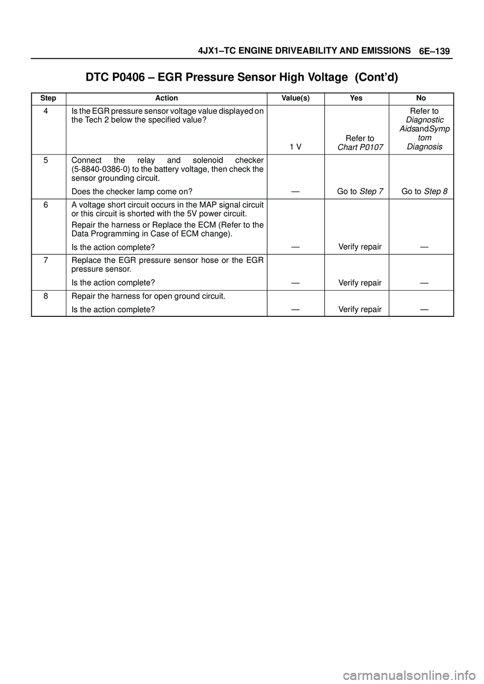
6E±139 4JX1±TC ENGINE DRIVEABILITY AND EMISSIONS
DTC P0406 ± EGR Pressure Sensor High Voltage������ ���
StepNo Ye s Value(s) Action
4Is the EGR pressure sensor voltage value displayed on
the Tech 2 below the specified value?
1 V
Refer to
Chart P0107
Refer to
Diagnostic
Aids
andSymp
tom
Diagnosis
5Connect the relay and solenoid checker
(5-8840-0386-0) to the battery voltage, then check the
sensor grounding circuit.
Does the checker lamp come on?
ÐGo to Step 7Go to Step 8
6A voltage short circuit occurs in the MAP signal circuit
or this circuit is shorted with the 5V power circuit.
Repair the harness or Replace the ECM (Refer to the
Data Programming in Case of ECM change).
Is the action complete?
ÐVerify repairÐ
7Replace the EGR pressure sensor hose or the EGR
pressure sensor.
Is the action complete?
ÐVerify repairÐ
8Repair the harness for open ground circuit.
Is the action complete?
ÐVerify repairÐ
Page 2063 of 3573
 P1655 (Flash DTC 17)
Thermo Relay Circuit Open/Short
060RW130
Circuit Description
The thermo relay circuit receives cu")
6E±170
4JX1±TC ENGINE DRIVEABILITY AND EMISSIONS
Diagnostic Trouble Code (DTC) P1655 (Flash DTC 17)
Thermo Relay Circuit Open/Short
060RW130
Circuit Description
The thermo relay circuit receives current through air con
10A fuse from the battery, current flowing in the order of
the thermo relay and thermo SW.
Action Taken When the DTC Sets
�The ECM will illuminate the malfunction indicator lamp
(MIL) the first time the fault is detected.
�The ECM will store conditions which were present
when the DTC was set as Freeze Frame and in the
Failure Records data.
Conditions for Clearing the MIL/DTC
�DTC P1655 can be cleared by using the Tech 2 ªClear
Infoº function or by disconnecting the ECM battery
feed.
Diagnostic Aids
Check for the following conditions:
�Poor connection at ECM ± Inspect harness connectors
for backed-out terminals, improper mating, broken
locks, improperly formed or damaged terminals, and
poor terminal-to-wire connection.
�Damaged harness ± Inspect the wiring harness for
damage.
Page 2064 of 3573
Ye sNo
1Was the ªOn-Board Diagnostic (OBD) System Checkº
performed?
ÐGo to Step 2")
6E±171 4JX1±TC ENGINE DRIVEABILITY AND EMISSIONS
DTC P1655 ± Thermo Relay Circuit Open/Short�
StepActionValue(s)Ye sNo
1Was the ªOn-Board Diagnostic (OBD) System Checkº
performed?
ÐGo to Step 2
Go to OBD
System
Check
21. Ignition ªON,º engine ªOFF.º
2. Observe the ªBatteri Voltageº display on the Tech 2.
Is the ªBatteri Voltageº below the specified value?
11 VGo to Step 4Go to Step 3
31. Ignition ªON,º engine ªOFF.º
2. Review and record Tech 2 Failure Records data.
3. Operate the vehicle within Failure Records
conditions as noted.
4. Using a Tech 2, monitor the ªSpecific DTCº info for
DTC P1655.
Does the Tech 2 indicate DTC P1655 failed?
ÐGo to Step 4
Refer to
Diagnostic
Aids
4Check the Thermo Relay circuit for a poor connection
and replace the terminal if necessary.
Did the terminal require replacement?
ÐVerify repairGo to Step 5
5Check the Thermo Relay for damage.
Did the Thermo Relay require replacement?
ÐVerify repairGo to Step 6
6Check the Thermo Relay circuit for a poor connection
at the ECM and replace the terminal if necessary.
Did the terminal require replacement?
ÐVerify repairGo to Step 7
7Replace the ECM (Refer to the Data Programming in
Case of ECM change).
Is the action complete?
ÐVerify repairÐ
Page 2065 of 3573
 P1657 (Flash DTC 76)
ECM Main Relay Circuit Open/Short
060RW135
Circuit Description
The ECM main relay circuit receive")
6E±172
4JX1±TC ENGINE DRIVEABILITY AND EMISSIONS
Diagnostic Trouble Code (DTC) P1657 (Flash DTC 76)
ECM Main Relay Circuit Open/Short
060RW135
Circuit Description
The ECM main relay circuit receives current through ECM
50A fuse from the battery, current flowing in the order of
the ECM main relay and ECM.
Action Taken When the DTC Sets
�The ECM will illuminate the malfunction indicator lamp
(MIL) the first time the fault is detected.
�The ECM will store conditions which were present
when the DTC was set as Freeze Frame and in the
Failure Records data.
Conditions for Clearing the MIL/DTC
�DTC P1657 can be cleared by using the Tech 2 ªClear
Infoº function or by disconnecting the ECM battery
feed.
Diagnostic Aids
Check for the following conditions:
�Poor connection at ECM ± Inspect harness connectors
for backed-out terminals, improper mating, broken
locks, improperly formed or damaged terminals, and
poor terminal-to-wire connection.
�Damaged harness ± Inspect the wiring harness for
damage.
Page 2066 of 3573
Ye sNo
1Was the ªOn-Board Diagnostic (OBD) System Checkº
performed?
ÐGo to Step")
6E±173 4JX1±TC ENGINE DRIVEABILITY AND EMISSIONS
DTC P1657 ± ECM Main Relay Circuit Open/Short�
StepActionValue(s)Ye sNo
1Was the ªOn-Board Diagnostic (OBD) System Checkº
performed?
ÐGo to Step 2
Go to OBD
System
Check
21. Check the Fuse 50A´ECM and 15A´Eng.
2. If the Fuse is open, replace it as necessary.
Was the Fuse open?
ÐVerify repairGo to Step 3
31. Ignition ªON,º engine ªOFF.º
2. Review and record Tech 2 Failure Records data.
3. Operate the vehicle within Failure Records
conditions as noted.
4. Using a Tech 2, monitor the ªDTCº info for DTC
P1657.
Does the Tech 2 indicate DTC P1657 failed?
ÐGo to Step 4
Refer to
Diagnostic
Aids
4Check the ECM Main Relay circuit between the Fuse
and the ECM Main Relay for a poor connection and
repair the terminal if necessary.
Did the terminal require repair?
ÐVerify repairGo to Step 5
5Check the ECM Main Relay for a damage and Replace
the ECM (Refer to the Data Programming in Case of
ECM change) Main Relay if necessary.
Did the ECM Main Relay require replacement?
ÐVerify repairGo to Step 6
6Check the ECM Main Relay circuit for a poor
connection at the ECM and replace the terminal if
necessary.
Did the terminal require replacement?
ÐVerify repairGo to Step 7
7Check the ECM Main Relay Ground circuit for a poor
connection and repair the terminal if necessary.
Did the terminal require repair?
ÐVerify repairGo to Step 8
8Check the ECM Main Relay power circuit for a poor
connection and repair the terminal if necessary.
Did the terminal require repair?
ÐVerify repairGo to Step 9
9Replace the ECM (Refer to the Data Programming in
Case of ECM change) Main Relay.
Is the action complete?
ÐVerify repairGo to Step 10
10Replace the ECM (Refer to the Data Programming in
Case of ECM change).
Is the action complete?
ÐVerify repairÐ
 P0380 (Flash DTC 66)
Glow Relay Circuit Open/Short
060RW132
Circuit Description
Glow relay circuit receives current th")