1998 ISUZU TROOPER relay
[x] Cancel search: relayPage 2576 of 3573
WIPER/WASHER SYSTEM8B–7
Rear Wiper/Washer System
General Description
The circuit consists of the starter switch, rear wiper &
washer switch, rear wiper motor, rear washer motor and
rear intermittent relay.When the wiper & washer switch is turned on with the
starter switch on, the battery voltage is applied to the
wiper motor to activate the wiper.
The washer motor squirts glass cleaning fluid while the
washer switch is being pushed. The intermittent relay is
used to control motion of the wiper.
Rear Wiper and Washer Switch
Removal
1. Disconnect the battery ground cable.
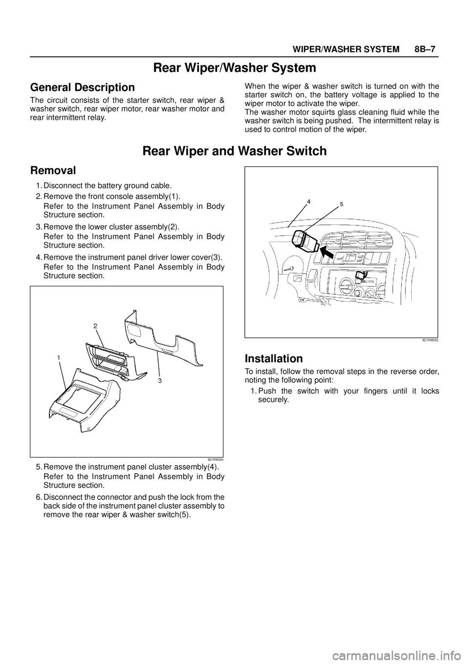
2. Remove the front console assembly(1).
Refer to the Instrument Panel Assembly in Body
Structure section.
3. Remove the lower cluster assembly(2).
Refer to the Instrument Panel Assembly in Body
Structure section.
4. Remove the instrument panel driver lower cover(3).
Refer to the Instrument Panel Assembly in Body
Structure section.
821RW024
5. Remove the instrument panel cluster assembly(4).
Refer to the Instrument Panel Assembly in Body
Structure section.
6. Disconnect the connector and push the lock from the
back side of the instrument panel cluster assembly to
remove the rear wiper & washer switch(5).
821RW023
Installation
To install, follow the removal steps in the reverse order,
noting the following point:
1. Push the switch with your fingers until it locks
securely.
Page 2578 of 3573
WIPER/WASHER SYSTEM8B–9
Alarm & Relay Control Unit
Removal
1. Disconnect the battery ground cable.
2. Remove the glove box.
3. Remove the instrument panel passenger lower cover
assembly.
4. Remove the passenger Knee bolster reinforcement
assembly.
5. Remove the fixing bolts, disconnect the connectors
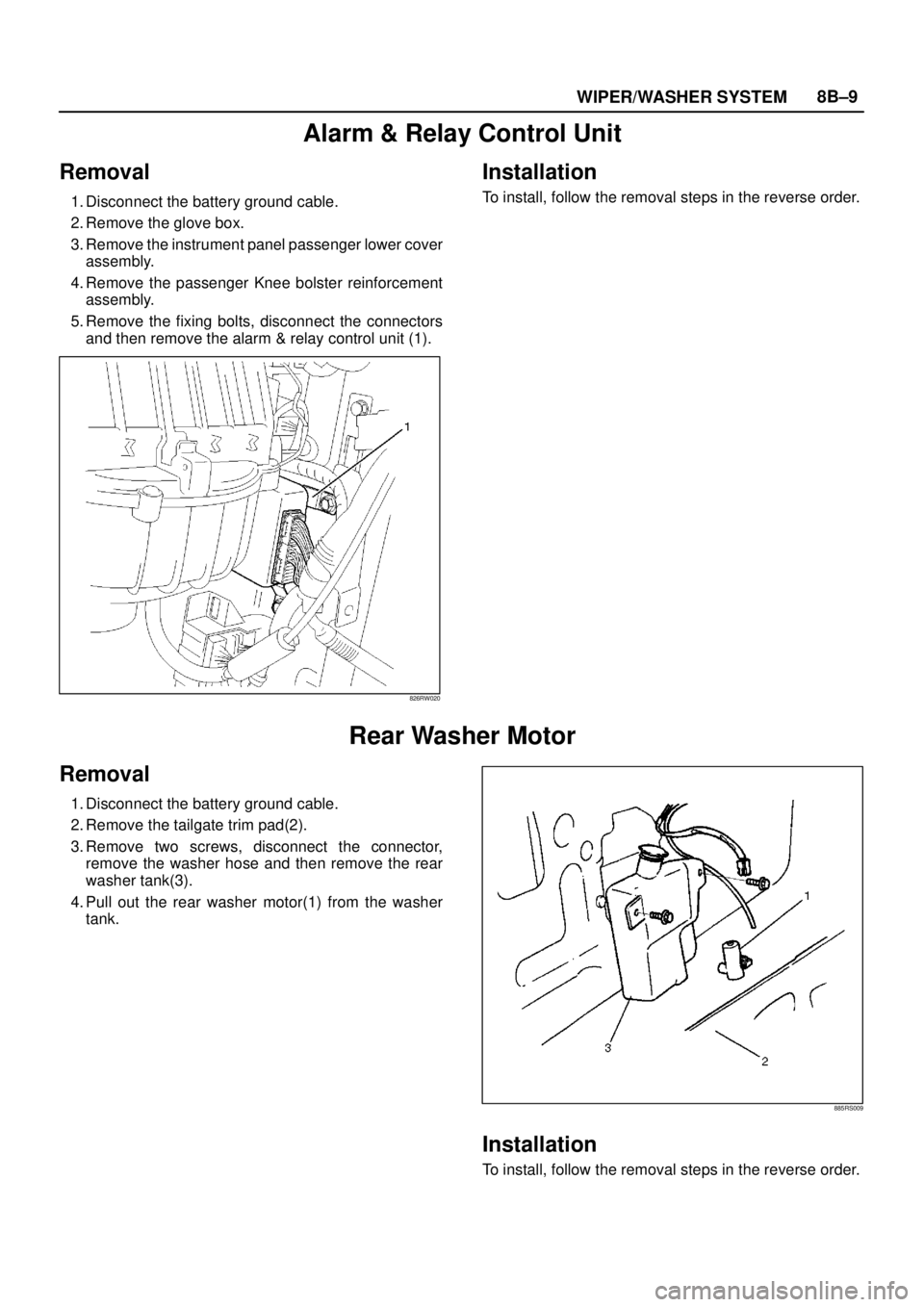
and then remove the alarm & relay control unit (1).
826RW020
Installation
To install, follow the removal steps in the reverse order.
Rear Washer Motor
Removal
1. Disconnect the battery ground cable.
2. Remove the tailgate trim pad(2).
3. Remove two screws, disconnect the connector,
remove the washer hose and then remove the rear
washer tank(3).
4. Pull out the rear washer motor(1) from the washer
tank.
885RS009
Installation
To install, follow the removal steps in the reverse order.
Page 2594 of 3573
WIRING SYSTEM 8DÐ1
BODY AND ACCESSORIES
WIRING SYSTEM
CONTENTS
Service Precautions . . . . . . . . . . . . . . . . . . . 8DÐ3
General Description . . . . . . . . . . . . . . . . . . . 8DÐ4Notes for Working on Electrical Items . . 8DÐ4
Symbols and Abbreviations . . . . . . . . . . . 8DÐ10
Parts for Electrical Circuit . . . . . . . . . . . . . 8DÐ12
Reading the Circuit Diagram . . . . . . . . . . 8DÐ21
Main Data and Specifications . . . . . . . . . . . 8DÐ24 Fuse, Fusible Link and Circuit Breaker Location . . . . . . . . . . . . . . . . . . . . . . . . . . . 8DÐ24
Relay Location . . . . . . . . . . . . . . . . . . . . . . 8DÐ27
Diode Location . . . . . . . . . . . . . . . . . . . . . . 8DÐ30
Grounding Point . . . . . . . . . . . . . . . . . . . . . 8DÐ33
Cable Harness Routing . . . . . . . . . . . . . . . 8DÐ45
Fuse Block Circuit . . . . . . . . . . . . . . . . . . . . . 8DÐ53 Circuit Diagram. . . . . . . . . . . . . . . . . . . . . . 8DÐ54
Start and Charging . . . . . . . . . . . . . . . . . . . . 8DÐ67 General Description . . . . . . . . . . . . . . . . . . 8DÐ67
Circuit Diagram. . . . . . . . . . . . . . . . . . . . . . 8DÐ68
Parts Location . . . . . . . . . . . . . . . . . . . . . . . 8DÐ70
Powertrain Control Module (PCM) . . . . . . . 8DÐ80 General Description . . . . . . . . . . . . . . . . . . 8DÐ80
Circuit Diagram. . . . . . . . . . . . . . . . . . . . . . 8DÐ81
Parts Location . . . . . . . . . . . . . . . . . . . . . . . 8DÐ93
QOSIII (4JG2) . . . . . . . . . . . . . . . . . . . . . . . . . 8DÐ111 General Description . . . . . . . . . . . . . . . . . . 8DÐ111
Circuit Diagram. . . . . . . . . . . . . . . . . . . . . . 8DÐ112
Parts Location . . . . . . . . . . . . . . . . . . . . . . . 8DÐ114
QOS and EGR System (4JG2) . . . . . . . . . . . 8DÐ118 General Description . . . . . . . . . . . . . . . . . . 8DÐ118
Circuit Diagram. . . . . . . . . . . . . . . . . . . . . . 8DÐ119
Parts Location . . . . . . . . . . . . . . . . . . . . . . . 8DÐ122
Headlight and Fog Light . . . . . . . . . . . . . . . . 8DÐ127 General Description . . . . . . . . . . . . . . . . . . 8DÐ127
Circuit Diagram. . . . . . . . . . . . . . . . . . . . . . 8DÐ128
Parts Location . . . . . . . . . . . . . . . . . . . . . . . 8DÐ130
Diagnosis . . . . . . . . . . . . . . . . . . . . . . . . . . . 8DÐ134
Rear Foglight . . . . . . . . . . . . . . . . . . . . . . . . . 8DÐ150 Circuit Diagram. . . . . . . . . . . . . . . . . . . . . . 8DÐ151
Parts Location . . . . . . . . . . . . . . . . . . . . . . . 8DÐ152
Headlight Leveling . . . . . . . . . . . . . . . . . . . . 8DÐ153 General Description . . . . . . . . . . . . . . . . . . 8DÐ153
Circuit Diagram. . . . . . . . . . . . . . . . . . . . . . 8DÐ154
Parts Location . . . . . . . . . . . . . . . . . . . . . . . 8DÐ155
Diagnosis . . . . . . . . . . . . . . . . . . . . . . . . . . . 8DÐ156
Clearance Light, Taillight and License Plate Light . . . . . . . . . . . . . . . . . . . . 8DÐ159 General Description . . . . . . . . . . . . . . . . . . 8DÐ159
Circuit Diagram. . . . . . . . . . . . . . . . . . . . . . 8DÐ160
Parts Location . . . . . . . . . . . . . . . . . . . . . . . 8DÐ163
Diagnosis . . . . . . . . . . . . . . . . . . . . . . . . . . . 8DÐ168
Interior Illumination Light . . . . . . . . . . . . . . 8DÐ180 General Description . . . . . . . . . . . . . . . . . . 8DÐ180
Circuit Diagram. . . . . . . . . . . . . . . . . . . . . . 8DÐ181
Parts Location . . . . . . . . . . . . . . . . . . . . . . . 8DÐ185
Diagnosis . . . . . . . . . . . . . . . . . . . . . . . . . . . 8DÐ192
Turn Signal Light and Hazard Warning Light . . . . . . . . . . . . . . . . . . . . . . . . . . . . . . . . 8DÐ193
General Description . . . . . . . . . . . . . . . . . . 8DÐ193
Circuit Diagram. . . . . . . . . . . . . . . . . . . . . . 8DÐ194
Parts Location . . . . . . . . . . . . . . . . . . . . . . . 8DÐ197
Diagnosis . . . . . . . . . . . . . . . . . . . . . . . . . . . 8DÐ202
Stoplight . . . . . . . . . . . . . . . . . . . . . . . . . . . . . 8DÐ208 General Description . . . . . . . . . . . . . . . . . . 8DÐ208
Circuit Diagram. . . . . . . . . . . . . . . . . . . . . . 8DÐ209
Parts Location . . . . . . . . . . . . . . . . . . . . . . . 8DÐ212
Diagnosis . . . . . . . . . . . . . . . . . . . . . . . . . . . 8DÐ216
Backup Light. . . . . . . . . . . . . . . . . . . . . . . . . . 8DÐ220 General Description . . . . . . . . . . . . . . . . . . 8DÐ220
Circuit Diagram. . . . . . . . . . . . . . . . . . . . . . 8DÐ221
Parts Location . . . . . . . . . . . . . . . . . . . . . . . 8DÐ223
Diagnosis . . . . . . . . . . . . . . . . . . . . . . . . . . . 8DÐ227
Horn . . . . . . . . . . . . . . . . . . . . . . . . . . . . . . . . . 8DÐ230 General Description . . . . . . . . . . . . . . . . . . 8DÐ230
Circuit Diagram. . . . . . . . . . . . . . . . . . . . . . 8DÐ231
Parts Location . . . . . . . . . . . . . . . . . . . . . . . 8DÐ232
Diagnosis . . . . . . . . . . . . . . . . . . . . . . . . . . . 8DÐ235
Dome Light, Luggage Room Light, Courtesy Light and Map Light . . . . . . . . . . 8DÐ237
General Description . . . . . . . . . . . . . . . . . . 8DÐ237
Circuit Diagram. . . . . . . . . . . . . . . . . . . . . . 8DÐ238
Parts Location . . . . . . . . . . . . . . . . . . . . . . . 8DÐ240
Power Door Lock . . . . . . . . . . . . . . . . . . . . . . 8DÐ244 General Description . . . . . . . . . . . . . . . . . . 8DÐ244
Circuit Diagram. . . . . . . . . . . . . . . . . . . . . . 8DÐ245
Parts Location . . . . . . . . . . . . . . . . . . . . . . . 8DÐ250
Diagnosi s. . . . . . . . . . . . . . . . . . . . . . . . . . . 8DÐ2 56
Power Window . . . . . . . . . . . . . . . . . . . . . . . 8DÐ261 General Description . . . . . . . . . . . . . . . . . . 8DÐ261
Circuit Diagram. . . . . . . . . . . . . . . . . . . . . . 8DÐ262
Parts Location . . . . . . . . . . . . . . . . . . . . . . . 8DÐ263
Diagnosis . . . . . . . . . . . . . . . . . . . . . . . . . . . 8DÐ266
Cruise Control . . . . . . . . . . . . . . . . . . . . . . . . 8DÐ272
Page 2597 of 3573
8DÐ4 WIRING SYSTEM
The chassis electrical system is a 12Ðvolt system with a
negative ground polarity.
Wire size are appropriate to respective circuits, and
classified by color. (The classification of harnesses by
color is shown on the circuit diagram for ease of harness
identification.)
The wire size is determined by load capacity and the
length of wire required.
The vehicle harnesses are: body harness, chassis
harness, engine room harness, instrument harness,
transmission harness, engine ECGI harness, dome light
harness, door harness, rear body harness, tailgate
harness, SRS harness and battery cables.
The harnesses are protected either by tape or corrugated
tube, depending on harness location.
The circuit for each system consists of the power source,
wire, fuse, relay, switch, load parts and ground, all of
which are shown on the circuit diagram.
In this section, each electrical device is classified by
system.
For major parts shown on the circuit based on the circuit
diagram for each system, a summary, diagnosis of
troubles and inspection procedures are detailed.
Notes for Working on Electrical
Items
Disconnecting the Battery Cable
1. All switches should be in the ÒOFFÓ position.
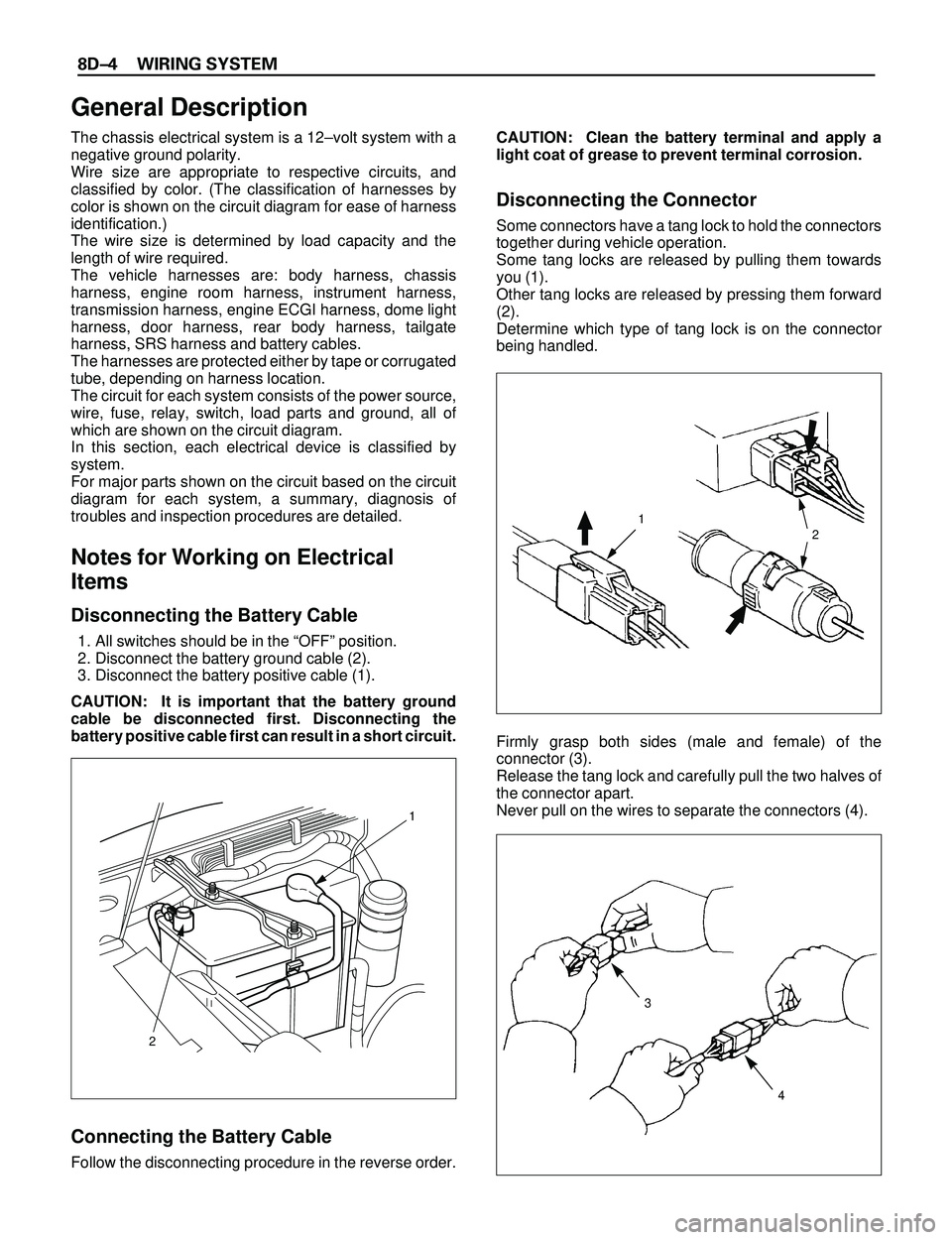
2. Disconnect the battery ground cable (2).
3. Disconnect the battery positive cable (1).
CAUTION: It is important that the battery ground
cable be disconnected first. Disconnecting the
battery positive cable first can result in a short circuit.
Connecting the Battery Cable
Follow the disconnecting procedure in the reverse order.CAUTION: Clean the battery terminal and apply a
light coat of grease to prevent terminal corrosion.
Disconnecting the Connector
Some connectors have a tang lock to hold the connectors
together during vehicle operation.
Some tang locks are released by pulling them towards
you (1).
Other tang locks are released by pressing them forward
(2).
Determine which type of tang lock is on the connector
being handled.
Firmly grasp both sides (male and female) of the
connector (3).
Release the tang lock and carefully pull the two halves of
the connector apart.
Never pull on the wires to separate the connectors (4).
2
1
General Description
1
2
3
4
Page 2598 of 3573
WIRING SYSTEM 8DÐ5
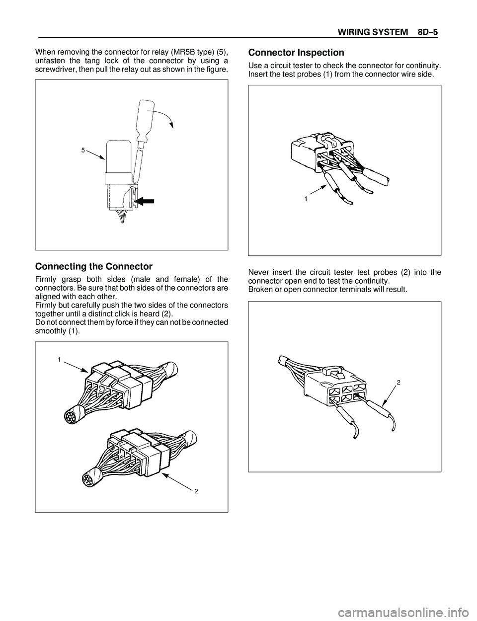
When removing the connector for relay (MR5B type) (5),
unfasten the tang lock of the connector by using a
screwdriver, then pull the relay out as shown in the figure.
Connecting the Connector
Firmly grasp both sides (male and female) of the
connectors. Be sure that both sides of the connectors are
aligned with each other.
Firmly but carefully push the two sides of the connectors
together until a distinct click is heard (2).
Do not connect them by force if they can not be connected
smoothly (1).
Connector Inspection
Use a circuit tester to check the connector for continuity.
Insert the test probes (1) from the connector wire side.
Never insert the circuit tester test probes (2) into the
connector open end to test the continuity.
Broken or open connector terminals will result.
5
1
2
1
2
Page 2603 of 3573
8DÐ10 WIRING SYSTEM
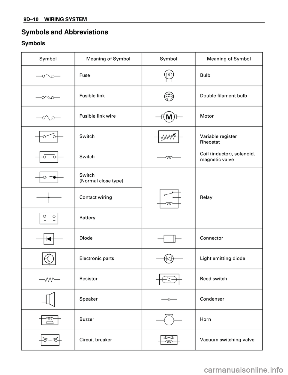
Symbols and Abbreviations
Symbols
Symbol Meaning of Symbol
Fuse
Fusible link
Fusible link wire
Switch
Switch
Contact wiring
Battery
Diode
Electronic parts
Resistor
Speaker
Buzzer
Circuit breakerSymbol Meaning of Symbol
Bulb
Double filament bulb
Motor
Variable register
Rheostat
Coil (inductor), solenoid,
magnetic valve
Relay
Connector
Light emitting diode
Reed switch
Condenser
Horn
Vacuum switching valve
+
–
Switch
(Normal close type)
M
Page 2609 of 3573
8DÐ16 WIRING SYSTEM
Circuit Breaker
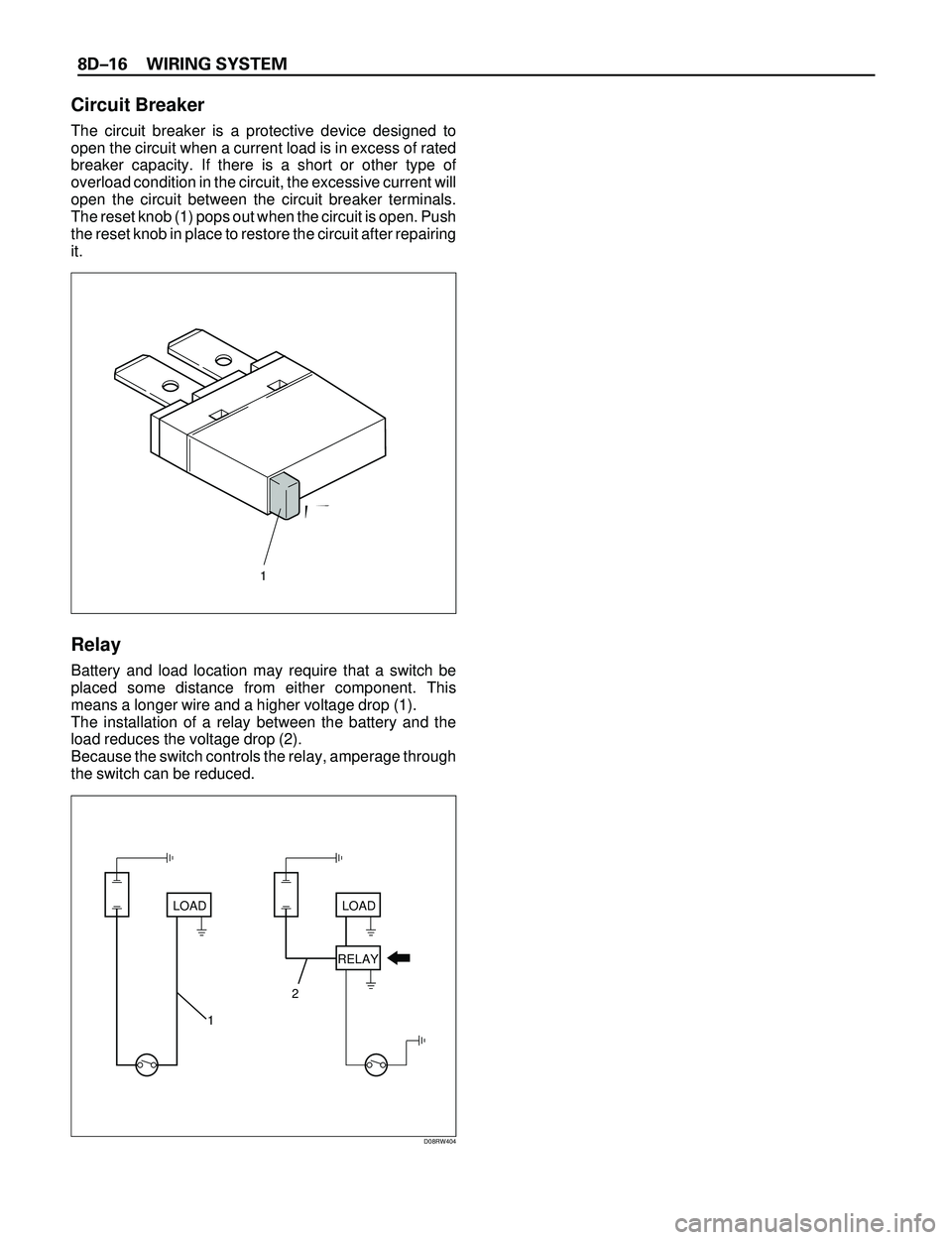
The circuit breaker is a protective device designed to
open the circuit when a current load is in excess of rated
breaker capacity. If there is a short or other type of
overload condition in the circuit, the excessive current will
open the circuit between the circuit breaker terminals.
The reset knob (1) pops out when the circuit is open. Push
the reset knob in place to restore the circuit after repairing
it.
Relay
Battery and load location may require that a switch be
placed some distance from either component. This
means a longer wire and a higher voltage drop (1).
The installation of a relay between the battery and the
load reduces the voltage drop (2).
Because the switch controls the relay, amperage through
the switch can be reduced.
Push
LOAD
12LOAD
RELAY
D08RW404
1
Page 2610 of 3573
WIRING SYSTEM 8DÐ17
Name/
ColorRated
voltage/Coil
resistanceInternal circuitName/
ColorRated
voltage/Coil
resistanceInternal circuit
1M
(MR5L)/
Black
12V/
Approx.
80W
Minimum
operating
voltage: 7V
at 77˚F (25˚C)2M
(MR5)/
Brown12V/
Approx.
80W
Minimum
operating
voltage: 7V
at 77˚F (25˚C)
1B
(MR5L)/
Grey1B-1M
(MR5)/
Grey
1M
(MR5)/
Black
(Case),
Blue
(Base)1M
1T
(MR5)/
Black/
Blue1M
(MR5B)/
BlackMinimum
operating
voltage: 9V
at 68˚F (20˚C)
12V
Minimum
operating
voltage:
4.3V at 77˚F
(25˚C)
1M
(Horn
relay)12V/
Minimum
operating
voltage: 8V
at 68˚F (20˚C)
Á À ÂÃ Á Ã
À
Â
Á À ÂÃ Á Ã
À
Â
Ä Ã ÀÂ
Â
ÀÃ
Ä
Ä Ã À
Â
Â
ÀÃ
Ä
Á
Á
ÁÂÀ
À
Á Â
Ä À
Ã
Ä
ÁÂ
ÅÀ
Â
Á
Ã
Å
Ä À
Ã
Ä
Á
Å
Â
À
ÁÃ ÅÂ
Á À ÂÃ
 ÃÀ Á
 À ÁÃ
Á Ã
À Â
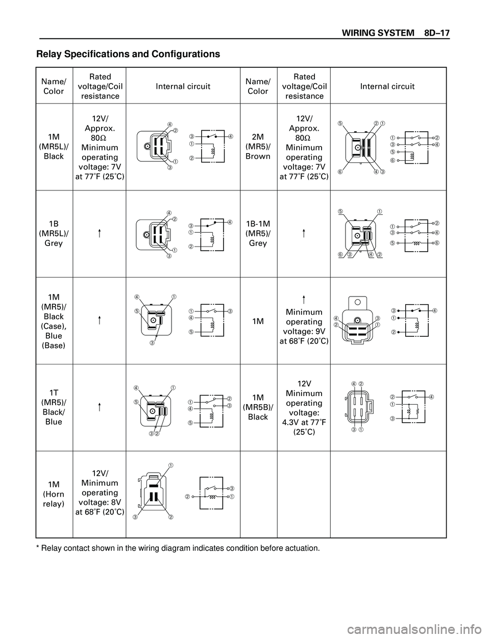
Relay Specifications and Configurations
* Relay contact shown in the wiring diagram indicates condition before actuation.