Page 3134 of 3573
WIRING SYSTEM 8D – 541
Circuit Diagram (RHD 6VE1)-3
D08RW612
4H SW
(TRANSFER)T.O.D. CONTROL UNIT
7
A-3
TRANSFER9H-49
A-3
0.5
B/L 0.85
B4
A-36H-495
H-49
3H-498
B-67
0.85
B0.5
GR/R0.5
GR/L
0.5
GR/L
0.5
B
0.5
B/L 0.5
GR/R 12
B-68
3
B-68
4
B-67
11
B-67
6
4L SW
(TRANSFER)12
A-3
H-84
13H-5
E-30 1.25
B/L
1.0
B/L
E-29
3
E-52
E-5
14
H-5 5
H-6
COMMON
CHAMBER COMMON
CHAMBERB-68
9H-76
C-63
C-63
C-63
B-68
10H-8
7
C-63B-68
8H-8
8
54
C-63H-7
16 819
B
B
A
B-67
9
0.5
B/L0.5
B/L0.5
B/L0.85
R/W
0.85
L
0.75
L
0.8
L0.8
R 0.8
G
0.5
B/L
0.5
B/P0.5
B/L0.5
B/L 0.5
O/B0.3
W
0.3
W0.85
G/W0.85
G/W
0.5
O/B
1.25
B/P
1.0
B/R0.75
LPCM
(E8)
PCM
(A1) PCM
(D8)
6
B-68 EHCU
(27)
1
E-5THROTTLE POSITION
SENSORDATA LINK
CONNECTOR
20
H-15
1
B-68 TAIL RELAY
(3)
3
H-15
0.3
G0.5
LG/R0.5
P
3
B-67 EHCU
(9)EHCU : ELECTRONIC
HYDRAULIC
CONTROL UNIT
9
H-15
Page 3141 of 3573
8D – 548 WIRING SYSTEM
Parts Location (RHD)
Legend
(1) I-9
(2) SRS Coil Assembly
(3) U-5
(4) U-1
(5) H-7, H-65
(6) C-16
(7) C-63(8) H-5
(9) E-30
(10) U-2
(11) Fuse Box
(12) Relay and Fuse Box
(13) H-61, H-62
(14) Fuse Box (C-21)
D08RW622
14
1
2345
6
7
8
9
10
11
12
13
Page 3142 of 3573
WIRING SYSTEM 8D – 549
Parts Location (LHD)
Legend
(1) SRS Coil Assembly
(2) I-37
(3) C-63
(4) H-7
(5) Fuse Box (H-49)
(6) H-52
(7) H-51(8) C-16
(9) U-6
(10) U-5
(11) SDM
(12) U-2
(13) U-1
(14) Relay and Fuse Box
D08RW997
2 1
3
4
5 6 7 8
9 10
11 12 13 14
Page 3418 of 3573

EXTERIOR/INTERIOR TRIM8J±39
Power Window System
General Description
The circuit consists of the starter switch, (door lock &)
power window switch for each of the front windows,
power window switch for rear windows and power window
motors.
When the starter switch is turned on, the battery voltage is
applied to each of the power window switches through the
circuit breaker and the power window relay on the circuit.
The ªDownº switch of the driver's power window switch
has a built-in function which can be operated by just
touching it.
Accordingly, the window will roll down automatically by
just setting the switch to the ªAUTOº position.
When the driver's power lock switch at the driver side is
depressed, the power source to the passenger's power
window switches are shut off. So, even if these switches
are operated, the power window motor will not operate.
Power Window Switch Removal and
Installation
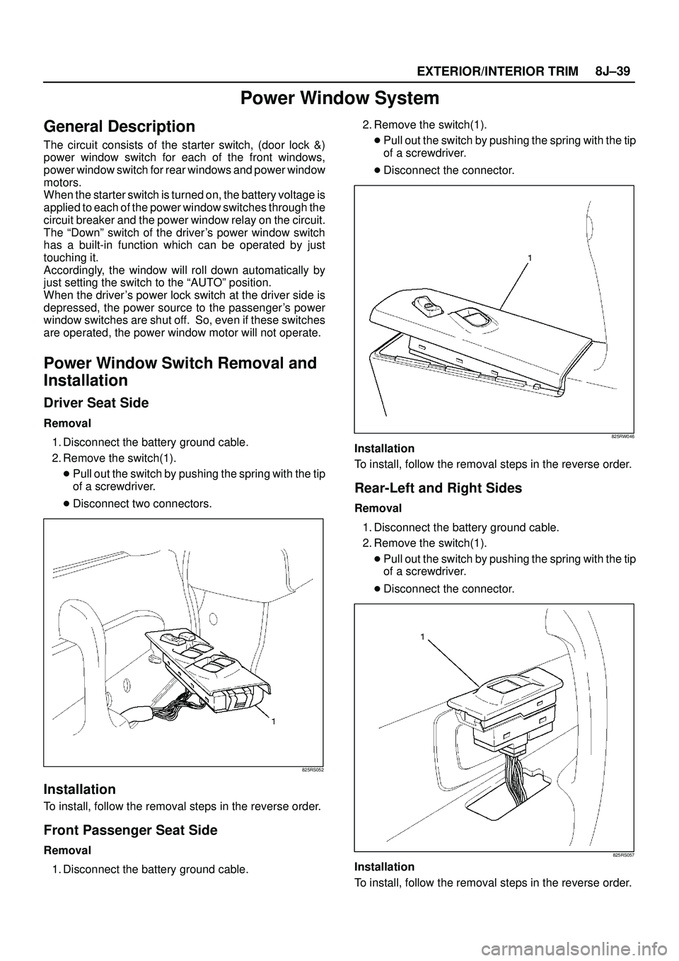
Driver Seat Side
Removal
1. Disconnect the battery ground cable.
2. Remove the switch(1).
�Pull out the switch by pushing the spring with the tip
of a screwdriver.
�Disconnect two connectors.
825RS052
Installation
To install, follow the removal steps in the reverse order.
Front Passenger Seat Side
Removal
1. Disconnect the battery ground cable.2. Remove the switch(1).
�Pull out the switch by pushing the spring with the tip
of a screwdriver.
�Disconnect the connector.
825RW046
Installation
To install, follow the removal steps in the reverse order.
Rear-Left and Right Sides
Removal
1. Disconnect the battery ground cable.
2. Remove the switch(1).
�Pull out the switch by pushing the spring with the tip
of a screwdriver.
�Disconnect the connector.
825RS057
Installation
To install, follow the removal steps in the reverse order.
Page 3441 of 3573

SUPPLEMENTAL RESTRAINT SYSTEM 9J±4
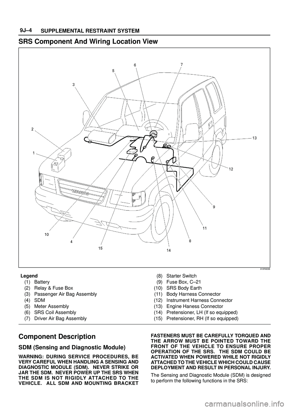
SRS Component And Wiring Location View
810RW298
Legend
(1) Battery
(2) Relay & Fuse Box
(3) Passenger Air Bag Assembly
(4) SDM
(5) Meter Assembly
(6) SRS Coil Assembly
(7) Driver Air Bag Assembly(8) Starter Switch
(9) Fuse Box, C±21
(10) SRS Body Earth
(11) Body Harness Connector
(12) Instrument Harness Connector
(13) Engine Haness Connector
(14) Pretensioner, LH (If so equipped)
(15) Pretensioner, RH (If so equipped)
Component Description
SDM (Sensing and Diagnostic Module)
WARNING:DURING SERVICE PROCEDURES, BE
VERY CAREFUL WHEN HANDLING A SENSING AND
DIAGNOSTIC MODULE (SDM). NEVER STRIKE OR
JAR THE SDM. NEVER POWER UP THE SRS WHEN
THE SDM IS NOT RIGIDLY ATTACHED TO THE
VEHICLE. ALL SDM AND MOUNTING BRACKETFASTENERS MUST BE CAREFULLY TORQUED AND
THE ARROW MUST BE POINTED TOWARD THE
FRONT OF THE VEHICLE TO ENSURE PROPER
OPERATION OF THE SRS. THE SDM COULD BE
ACTIVATED WHEN POWERED WHILE NOT RIGIDLY
ATTACHED TO THE VEHICLE WHICH COULD CAUSE
DEPLOYMENT AND RESULT IN PERSONAL INJURY.
The Sensing and Diagnostic Module (SDM) is designed
to perform the following functions in the SRS: