1998 ISUZU TROOPER relay
[x] Cancel search: relayPage 1873 of 3573

6D – 6 ENGINE ELECTRICAL
RELATION BETWEEN STARTER SWITCH AND STARTER
M
Key
PositionB1 B2 ACCIG1 IG2 ST
LOCKKey
Removed
Inserted OFF
ACC
ON
START
BSBattery
+-
2
17
3
4
5
6
Legend
(1) Starter Switch
(2) To Generator
(3) To QOS4 Control(4) Starter Relay
(5) Immobilizer Relay (for Europe)
(6) Magnetic Switch
(7) Battery
065R200029
Page 1874 of 3573
ENGINE ELECTRICAL 6D – 7
ON-VEHICLE SERVICE
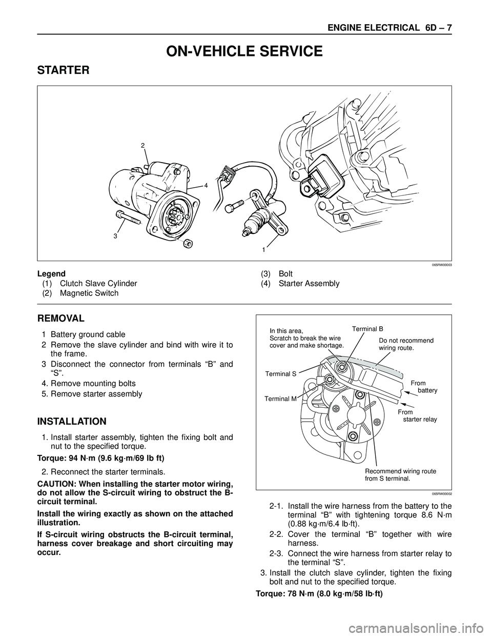
STARTER
REMOVAL
1 Battery ground cable
2 Remove the slave cylinder and bind with wire it to
the frame.
3 Disconnect the connector from terminals “B” and
“S”.
4. Remove mounting bolts
5. Remove starter assembly
INSTALLATION
1. Install starter assembly, tighten the fixing bolt and
nut to the specified torque.
Torque: 94 N·m (9.6 kg·m/69 lb ft)
2. Reconnect the starter terminals.
CAUTION: When installing the starter motor wiring,
do not allow the S-circuit wiring to obstruct the B-
circuit terminal.
Install the wiring exactly as shown on the attached
illustration.
If S-circuit wiring obstructs the B-circuit terminal,
harness cover breakage and short circuiting may
occur.2-1. Install the wire harness from the battery to the
terminal “B” with tightening torque 8.6 N·m
(0.88 kg·m/6.4 lb·ft).
2-2. Cover the terminal “B” together with wire
harness.
2-3. Connect the wire harness from starter relay to
the terminal “S”.
3. Install the clutch slave cylinder, tighten the fixing
bolt and nut to the specified torque.
Torque: 78 N·m (8.0 kg·m/58 lb·ft)
1
32
4
Legend
(1) Clutch Slave Cylinder
(2) Magnetic Switch(3) Bolt
(4) Starter Assembly
065RW00003
Do not recommend
wiring route.
Recommend wiring route
from S terminal.From
battery
From
starter relay Terminal B
Terminal MTerminal SIn this area,
Scratch to break the wire
cover and make shortage.
065RW00002
Page 1882 of 3573
ENGINE ELECTRICAL 6D – 15
CHARGING SYSTEM
GENERAL DESCRIPTION
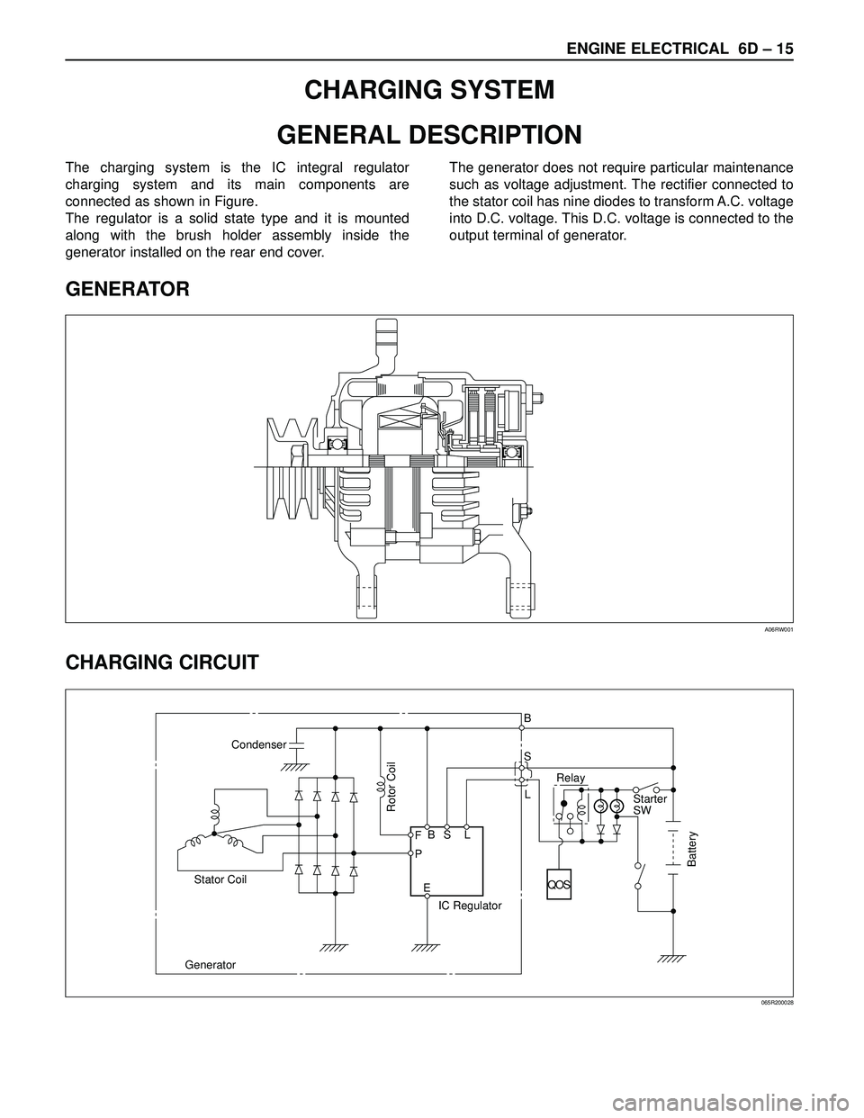
GENERATOR
CHARGING CIRCUIT
The charging system is the IC integral regulator
charging system and its main components are
connected as shown in Figure.
The regulator is a solid state type and it is mounted
along with the brush holder assembly inside the
generator installed on the rear end cover.The generator does not require particular maintenance
such as voltage adjustment. The rectifier connected to
the stator coil has nine diodes to transform A.C. voltage
into D.C. voltage. This D.C. voltage is connected to the
output terminal of generator.
A06RW001
Condenser
GeneratorStator Coil
IC RegulatorStarter
SW
Rotor Coil
Battery
P F
EBS LRelay B
S
L
QOS
065R200028
Page 1883 of 3573
6D – 16 ENGINE ELECTRICAL
DIAGNOSIS
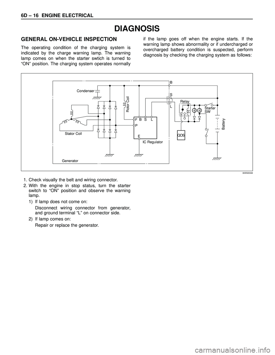
GENERAL ON-VEHICLE INSPECTION
The operating condition of the charging system is
indicated by the charge warning lamp. The warning
lamp comes on when the starter swtich is turned to
“ON” position. The charging system operates normallyif the lamp goes off when the engine starts. If the
warning lamp shows abnormality or if undercharged or
overcharged battery condition is suspected, perform
diagnosis by checking the charging system as follows:
Condenser
GeneratorStator Coil
IC RegulatorStarter
SW
Rotor Coil
Battery
P F
EBS LRelay B
S
L
QOS
065R200028
1. Check visually the belt and wiring connector.
2. With the engine in stop status, turn the starter
switch to “ON” position and observe the warning
lamp.
1) If lamp does not come on:
Disconnect wiring connector from generator,
and ground terminal “L” on connector side.
2) If lamp comes on:
Repair or replace the generator.
Page 1890 of 3573
ENGINE ELECTRICAL 6D – 23
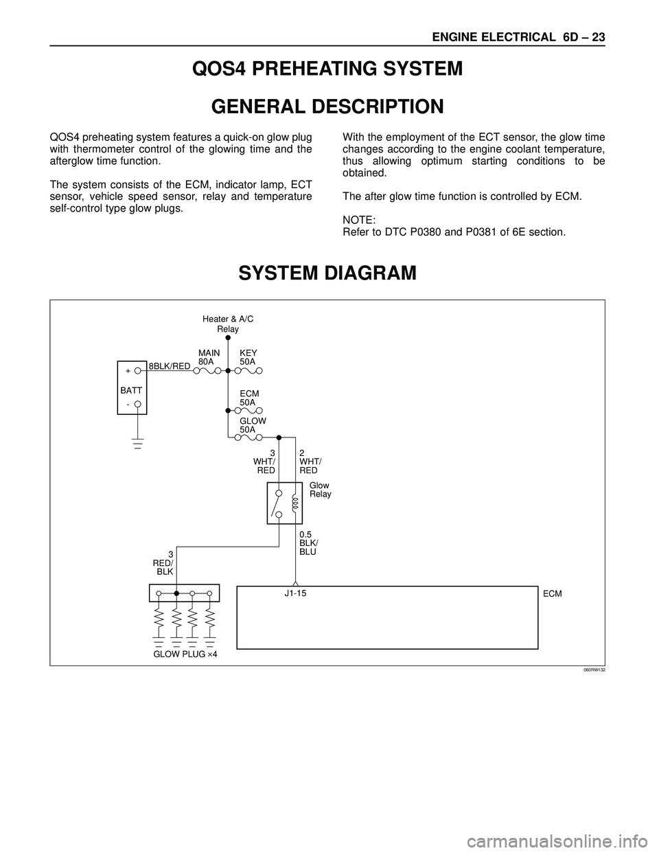
QOS4 PREHEATING SYSTEM
GENERAL DESCRIPTION
QOS4 preheating system features a quick-on glow plug
with thermometer control of the glowing time and the
afterglow time function.
The system consists of the ECM, indicator lamp, ECT
sensor, vehicle speed sensor, relay and temperature
self-control type glow plugs.With the employment of the ECT sensor, the glow time
changes according to the engine coolant temperature,
thus allowing optimum starting conditions to be
obtained.
The after glow time function is controlled by ECM.
NOTE:
Refer to DTC P0380 and P0381 of 6E section.
SYSTEM DIAGRAM
+
-KEY
50A
ECM
50A
GLOW
50A
2
WHT/
RED
0.5
BLK/
BLU
ECM J1-15 3
WHT/
RED
3
RED/
BLKMAIN
80A
8BLK/RED
Glow
Relay
GLOW PLUG 4
BATTHeater & A/C
Relay
060RW132
Page 1891 of 3573
6D – 24 ENGINE ELECTRICAL
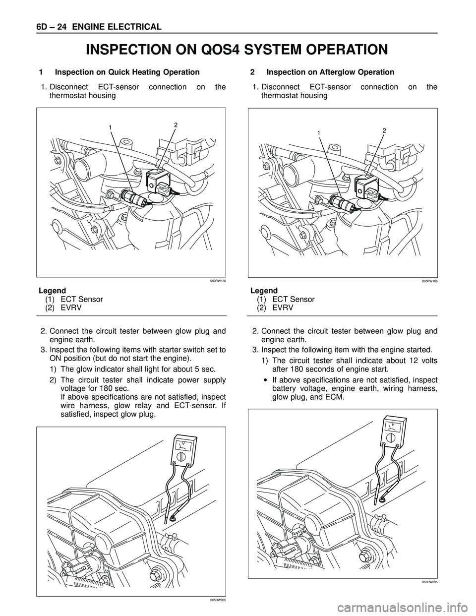
1 Inspection on Quick Heating Operation
1. Disconnect ECT-sensor connection on the
thermostat housing
Legend
(1) ECT Sensor
(2) EVRV
2. Connect the circuit tester between glow plug and
engine earth.
3. Inspect the following items with starter switch set to
ON position (but do not start the engine).
1) The glow indicator shall light for about 5 sec.
2) The circuit tester shall indicate power supply
voltage for 180 sec.
If above specifications are not satisfied, inspect
wire harness, glow relay and ECT-sensor. If
satisfied, inspect glow plug.2 Inspection on Afterglow Operation
1. Disconnect ECT-sensor connection on the
thermostat housing
Legend
(1) ECT Sensor
(2) EVRV
2. Connect the circuit tester between glow plug and
engine earth.
3. Inspect the following item with the engine started.
1) The circuit tester shall indicate about 12 volts
after 180 seconds of engine start.
•If above specifications are not satisfied, inspect
battery voltage, engine earth, wiring harness,
glow plug, and ECM.
12
060RW166
065RW035
12
060RW166
065RW035
INSPECTION ON QOS4 SYSTEM OPERATION
Page 1892 of 3573
ENGINE ELECTRICAL 6D – 25
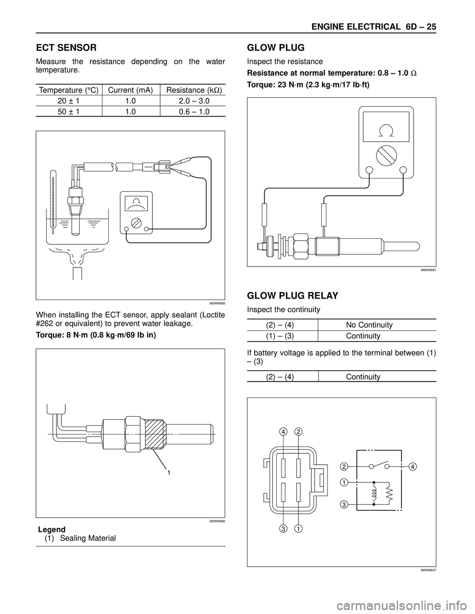
ECT SENSOR
Measure the resistance depending on the water
temperature.
Temperature (°C) Current (mA) Resistance (kΩ)
20 ± 1 1.0 2.0 – 3.0
50 ± 1 1.0 0.6 – 1.0
When installing the ECT sensor, apply sealant (Loctite
#262 or equivalent) to prevent water leakage.
Torque: 8 N·m (0.8 kg·m/69 lb in)
Legend
(1) Sealing Material
GLOW PLUG
Inspect the resistance
Resistance at normal temperature: 0.8 – 1.0 Ω
Torque: 23 N·m (2.3 kg·m/17 lb·ft)
GLOW PLUG RELAY
Inspect the continuity
(2) – (4) No Continuity
(1) – (3) Continuity
If battery voltage is applied to the terminal between (1)
– (3)
(2) – (4) Continuity065RW058
065RW061
1
065RW060
2 42
311
34
065RW037
Page 1897 of 3573
6E±4
4JX1±TC ENGINE DRIVEABILITY AND EMISSIONS
Diagnostic Aids 6E±122. . . . . . . . . . . . . . . . . . . . . . . .
Test Description 6E±122. . . . . . . . . . . . . . . . . . . . . . .
Diagnostic Trouble Code (DTC) P0380
(Flash DTC 66) Glow Relay Circuit
Open/Short 6E±126. . . . . . . . . . . . . . . . . . . . . . . . . . . .
Circuit Description 6E±126. . . . . . . . . . . . . . . . . . . . .
Action Taken When the DTC Sets 6E±126. . . . . . .
Conditions for Clearing the MIL/DTC 6E±126. . . . .
Diagnostic Aids 6E±126. . . . . . . . . . . . . . . . . . . . . . . .
Diagnostic Trouble Code (DTC) P0381
(Flash DTC 67) Glow Lamp Circuit
Open/Short 6E±128. . . . . . . . . . . . . . . . . . . . . . . . . . . .
Circuit Description 6E±128. . . . . . . . . . . . . . . . . . . . .
Action Taken When the DTC Sets 6E±128. . . . . . .
Conditions for Clearing the MIL/DTC 6E±128. . . . .
Diagnostic Aids 6E±128. . . . . . . . . . . . . . . . . . . . . . . .
Diagnostic Trouble Code (DTC) P1403
(Flash DTC 32) EGR EVRV Fault 6E±130. . . . . . . . .
Circuit Description 6E±130. . . . . . . . . . . . . . . . . . . . .
Diagnostic Aids 6E±130. . . . . . . . . . . . . . . . . . . . . . . .
Test Description 6E±130. . . . . . . . . . . . . . . . . . . . . . .
Diagnostic Trouble Code (DTC) P1404
(Flash DTC 31) EGR VSV Circuit 6E±132. . . . . . . . .
Circuit Description 6E±132. . . . . . . . . . . . . . . . . . . . .
Diagnostic Aids 6E±132. . . . . . . . . . . . . . . . . . . . . . . .
Diagnostic Trouble Code (DTC) P0405
(Flash DTC 26) EGR Pressure Sensor
Low Voltage 6E±134. . . . . . . . . . . . . . . . . . . . . . . . . . . .
Action Taken When the DTC Sets 6E±134. . . . . . .
Conditions for Clearing the MIL/DTC 6E±134. . . . .
Diagnostic Aids 6E±134. . . . . . . . . . . . . . . . . . . . . . . .
Diagnostic Trouble Code (DTC) P1405
(Flash DTC 37) EGR EVRV Circuit
Open/Short 6E±136. . . . . . . . . . . . . . . . . . . . . . . . . . . .
Circuit Description 6E±136. . . . . . . . . . . . . . . . . . . . .
Action Taken When the DTC Sets 6E±136. . . . . . .
Conditions for Clearing the MIL/DTC 6E±136. . . . .
Diagnostic Aids 6E±136. . . . . . . . . . . . . . . . . . . . . . . .
Diagnostic Trouble Code (DTC) P0406
(Flash DTC 26) EGR Pressure Sensor
High Voltage 6E±138. . . . . . . . . . . . . . . . . . . . . . . . . . .
Action Taken When the DTC Sets 6E±138. . . . . . .
Conditions for Clearing the MIL/DTC 6E±138. . . . .
Diagnostic Aids 6E±138. . . . . . . . . . . . . . . . . . . . . . . .
Diagnostic Trouble Code (DTC) P0475
(Flash DTC 71) EXH #1 VSV Circuit 6E±140. . . . . . .
Circuit Description 6E±140. . . . . . . . . . . . . . . . . . . . .
Action Taken When the DTC Sets 6E±140. . . . . . .
Conditions for Clearing the MIL/DTC 6E±140. . . . .
Diagnostic Aids 6E±140. . . . . . . . . . . . . . . . . . . . . . . .
Diagnostic Trouble Code (DTC) P1475
(Flash DTC 71) EXH #2 VSV Circuit
Open/Short 6E±142. . . . . . . . . . . . . . . . . . . . . . . . . . . .
Circuit Description 6E±142. . . . . . . . . . . . . . . . . . . . .
Action Taken When the DTC Sets 6E±142. . . . . . . Conditions for Clearing the MIL/DTC 6E±142. . . . .
Diagnostic Aids 6E±142. . . . . . . . . . . . . . . . . . . . . . . .
Diagnostic Trouble Code (DTC) P1485
(Flash DTC 74) ITP (Intake Thorottle Position)
Sensor Low Voltage 6E±144. . . . . . . . . . . . . . . . . . . . .
Circuit Description 6E±144. . . . . . . . . . . . . . . . . . . . .
Action Taken When the DTC Sets 6E±144. . . . . . .
Conditions for Clearing the MIL/DTC 6E±144. . . . .
Diagnostic Aids 6E±144. . . . . . . . . . . . . . . . . . . . . . . .
Diagnostic Trouble Code (DTC) P1486
(Flash DTC 74) ITP (Intake Throttle Position)
Sensor High Voltage 6E±146. . . . . . . . . . . . . . . . . . . .
Circuit Description 6E±146. . . . . . . . . . . . . . . . . . . . .
Action Taken When the DTC Sets 6E±146. . . . . . .
Conditions for Clearing the MIL/DTC 6E±146. . . . .
Diagnostic Aids 6E±146. . . . . . . . . . . . . . . . . . . . . . . .
Diagnostic Trouble Code (DTC) P1487
(Flash DTC 73) Intake Throttle System
Circuit Open/Start 6E±148. . . . . . . . . . . . . . . . . . . . . . .
Circuit Description 6E±148. . . . . . . . . . . . . . . . . . . . .
Action Taken When the DTC Sets 6E±148. . . . . . .
Conditions for Clearing the MIL/DTC 6E±148. . . . .
Diagnostic Aids 6E±148. . . . . . . . . . . . . . . . . . . . . . . .
Diagnostic Trouble Code (DTC) P1488
(Flash DTC 72) Intake Throttle Motor Control
Circuit Signal Gap 6E±150. . . . . . . . . . . . . . . . . . . . . .
Circuit Description 6E±150. . . . . . . . . . . . . . . . . . . . .
Action Taken When the DTC Sets 6E±150. . . . . . .
Conditions for Clearing the MIL/DTC 6E±150. . . . .
Diagnostic Aids 6E±150. . . . . . . . . . . . . . . . . . . . . . . .
Diagnostic Trouble Code (DTC) P0502
(Flash DTC 24) VSS (Vehicle Speed Sensor)
No Signal 6E±152. . . . . . . . . . . . . . . . . . . . . . . . . . . . . .
Circuit Description 6E±152. . . . . . . . . . . . . . . . . . . . .
Action Taken When the DTC Sets 6E±152. . . . . . .
Conditions for Clearing the MIL/DTC 6E±152. . . . .
Test Description 6E±153. . . . . . . . . . . . . . . . . . . . . . .
Diagnostic Trouble Code (DTC) P0510
(Flash DTC 75) Idle SW Malfunction, Open
Circuit 6E±155. . . . . . . . . . . . . . . . . . . . . . . . . . . . . . . . .
Circuit Description 6E±155. . . . . . . . . . . . . . . . . . . . .
Action Taken When the DTC Sets 6E±155. . . . . . .
Conditions for Clearing the MIL/DTC 6E±155. . . . .
Diagnostic Aids 6E±155. . . . . . . . . . . . . . . . . . . . . . . .
Diagnostic Trouble Code (DTC) P1510
(Flash DTC 75) Idle SW Malfunction
Short Circuit 6E±157. . . . . . . . . . . . . . . . . . . . . . . . . . .
Circuit Description 6E±157. . . . . . . . . . . . . . . . . . . . .
Action Taken When the DTC Sets 6E±157. . . . . . .
Conditions for Clearing the MIL/DTC 6E±157. . . . .
Diagnostic Aids 6E±157. . . . . . . . . . . . . . . . . . . . . . . .
Diagnostic Trouble Code (DTC) P0562
(Flash DTC 35) System Voltage Too Low 6E±159. .
Circuit Description 6E±159. . . . . . . . . . . . . . . . . . . . .
Action Taken When the DTC Sets 6E±159. . . . . . .