Page 907 of 3573
POWER ASSISTED BRAKE SYSTEM 5C – 29
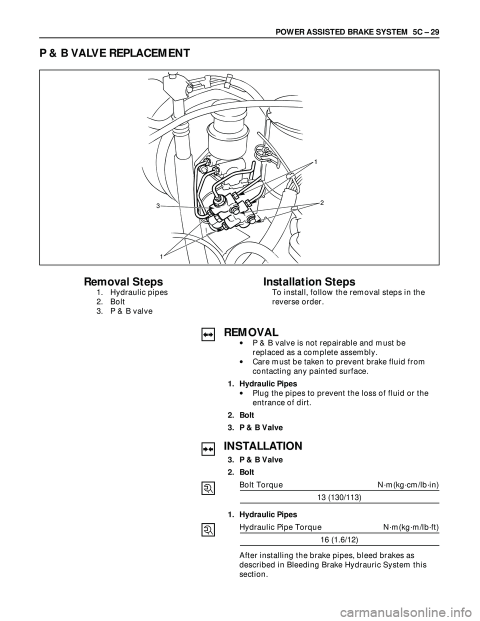
P & B VALVE REPLACEMENT
1
3
1�y�y
2
Removal Steps
1. Hydraulic pipes
2. Bolt
3. P & B valve
Installation Steps
To install, follow the removal steps in the
reverse order.
REMOVAL
•P & B valve is not repairable and must be
replaced as a complete assembly.
•Care must be taken to prevent brake fluid from
contacting any painted surface.
1. Hydraulic Pipes
•Plug the pipes to prevent the loss of fluid or the
entrance of dirt.
2. Bolt
3. P & B Valve
INSTALLATION
3. P & B Valve
2. Bolt
Bolt Torque N·m(kg·cm/lb·in)
13 (130/113)
1. Hydraulic Pipes
Hydraulic Pipe Torque N·m(kg·m/lb·ft)
16 (1.6/12)
After installing the brake pipes, bleed brakes as
described in Bleeding Brake Hydrauric System this
section.
Page 1530 of 3573

00 Ð 30 SERVICE INFORMATION
Fuel Filter Water Draining Procedure
The indicator light will come on when the water level in the
water separator exceeds the specified level.
Drain the water and foreign material from the water separa-
tor with the following procedure.
1. Find a safe place to park the vehicle.
2. Open the engine hood and place a container (Approxi-
mately 0.2 liter capacity) at the end of the vinyl hose
beneath the drain plug on the separator.
3. Loosen the drain plug by turning it counterclockwise
(Approximately 5 turns) and operate the priming pump
up and down about 10 times until water is drained
approximately 0.1 liter.
4. After draining, securely tighten the drain plug by turn-
ing it clockwise and operate the priming pump manu-
ally up and down several times.
5. After starting the engine, check to see that there is no
fuel leak from the drain plug.
Also check to see that the fuel filter water indicator light
has turned off.
If water separator requires frequent draining, have the
fuel tank drained for removal of water at your Isuzu
Dealer.
Air Bleeding
1. Loosen the bleeder screw on the injection pump over-
flow valve.
2. Operate the priming pump until fuel mixed with foam
flows from the bleeder screw.
3. Tighten the bleeder screw.
4. Operate the priming pump several times and check for
fuel leakage.
COOLING SYSTEM
Coolant Level
Check the coolant level and replenish the radiator reserve
tank as necessary.
If the coolant level falls below the ÒMINÓ line, carefully check
the cooling system for leakage. Then add enough coolant to
bring the level up to the ÒMAXÓ line.
NOTE:
Do not overfill the reserve tank.
Page 1671 of 3573
FUEL SYSTEM 6C Ð 5
FUEL FILTER AND WATER SEPARATOR
A cartridge type fuel filter and a water separator are used along with the VE type injection pump.
As the inside of the injection pump is lubricated by the fuel which it is pumping, the fuel must be perfectly
clean. The fuel filter and the water separator remove water particles and other foreign material from the
fuel before it reaches the injection pump.
The water separator has an internal float. When the float reaches the specified level, a warning light comes
on to remind you to drain the water from the water separator.
A diaphragm type priming pump is installed at the top of the water separator. It is used during the water
draining and the air bleeding procedures.
Page 1674 of 3573

6C Ð 8 FUEL SYSTEM
FUEL FILTER CARTRIGE
DISASSEMBLY
·Drain fuel completely from the fuel filter.
·Protect the filter body with cloth and lightly grip with
a vise.
·Remove sedimentor center.
·Remove the cartridge using a filter wrench.
Filter wrench: 5-8840-0253-0(J-22700)
REASSEMBLY
·Install the sedimentor center.
Clean the cartridge mounting surface of filter body
so that the cartridge can be securely.
Apply engine oil thinly to new cartridge o-ring.
·To facilitate bleeding, fill the new cartridge with
light oil.
·Tighten the cartridge until o-ring comes in contact
with the sealing, taking care not to spill the light
oil.
·Retighten 1/3~2/3 using a filter wrench.
Filter wrench: 5-8840-0253-0(J-22700)
Bleeding
·Operate priming pump to send the air in the fuel
system to the injection pump.
·Loosen injection pump bleeding plug, and operate
the priming pump until no bubble is made.
·Tighten the bleeding plug.
·Start the engine, and if it is not started in 10 sec-
onds or less, repeat the bleeding steps.
·Make sure of no fuel leakage, and tighten the
priming pump.
Draining
·When the water in the sedimentor reaches the
specified volume, warning light is actuated.
In this case, follow the draining steps below.
·Set a vinyI hose over the drain plug.
·Loosen the drain plug.
·To drain the water, operate the priming pump
several times.
·After draining, tighten the drain plug.
·Operate the priming pump several times to check
for fuel leakage.
·Check and see the warning light is off.
Page 1850 of 3573
ENGINE FUEL 6C – 5
FUEL FILTER
Legend
(1) Priming Pump
(2) Fuel Filter Cartridge
A cartridge type fuel filter is used along with the piston
type fuel pump on the high pressure oil pump.
The fuel filter removes foreign material from the fuel
before it reaches the fuel pump.
A diaphragm type priming pump is installed at the top of
the fuel filter. It is used during the air bleeding
procedures.
INJECTOR ASSEMBLY
Legend
(1) Oil Passage
(2) Fuel Passage
1. Construction of Fuel Injector
The fuel injector is comprised of the solenoid
section, hydraulic line, and fuel line. Fuel injection is
controlled by the continuity time signal and
continuity start timing signal sent by the ECM
(Electronic Control Module) to the solenoid.
2. Working of Fuel Injector
1) The ECM detects the working of the engine from
its input signals, such as engine speed
accelerator throttle opening, and engine coolant
temperature, sending the optimal signals to the
solenoid.
1
2
041RW017
1
2
055RW018
Page 1853 of 3573

6C – 8 ENGINE FUEL
REASSEMBLY
1. Clean the cartridge mounting surface of the filter
body so that the cartridge can be secured.
Apply engine oil thinly to new cartridge O-ring.
2. To facilitate bleeding, fill the new cartridge with light
oil.
3. Tighten the cartridge until O-ring comes in contact
with the seal, taking care not to spill the light oil.
4. Retighten 1/3 – 2/3 using a filter wrench.
Filter wrench: 5-8840-0203-0
Bleeding
1. Loosen air bleeding plug.
2. Operate priming pump to bleed the air in the fuel
line.
3. Operate the priming pump until the fuel is overflow
from air bleeding plug.
4. Tighten the air bleeding plug.
5. Start the engine, and if it is not started in 10
seconds or less, repeat the bleeding steps.
6. Make sure of no fuel leakage, and tighten the
priming pump.
Legend
(1) Priming Pump
NOTE: In comparison with the conventional engine,
the capacity of fuel passage in the 4JX1 engine is
larger. It takes the priming pump more time to fill the
engine with fuel.
012RW078
1
012RW111
Page 2530 of 3573

�Clutch pedal to dash panel
Torque: 21 N´m (2.1 kg´m/15 lb ft)
�Master cylinder push rod to yok")
CLUTCH7C±21
Torque Specifications
�Master cylinder to dash panel
Torque: 16 N´m (1.6 kg´m/12 lb ft)
�Clutch pedal to dash panel
Torque: 21 N´m (2.1 kg´m/15 lb ft)
�Master cylinder push rod to yoke
Torque: 17 N´m (1.7 kg´m/12 lb ft)
�Clutch pipe to master cylinder
Torque: 20 N´m (2.0 kg´m/14 lb ft)
�Clutch pipe to flex, hose
Torque:
M 10: 16 N´m (1.6 kg´m/12 lb ft)
M 12: 20 N´m (2.0 kg´m/14 lb ft)
�Slave cylinder to case
Torque: 43 N´m (4.4 kg´m/32 lb ft)
�Slave cylinder bleeder screw
Torque: 8 N´m (0.8 kg´m/69 lb in)
�Flexible hose to slave cylinder
Torque: 20 N´m (2.0 kg´m/14 lb ft)
�Clutch pipe to damper cylinder
Torque: 12 N´m (1.2 kg´m/104 lb in)
�Damper cylinder bleeder screw
Torque: 8 N´m (0.8 kg´m/69 lb in)
Bleeding
1. Check the level of clutch fluid in the reservoir and
replenish if necessary.
Bleeding the damper cylinder (except V6 LHD
model).
2. Remove the rubber cap from the bleeder screw and
wipe clean the bleeder screw. Connect a vinyl tube to
the bleeder screw and insert the other end of the vinyl
tube into a transparent container.
3. Pump the clutch pedal repeatedly and hold it
depressed.
203RS005
4. Loosen the bleeder screw to release clutch fluid with
air bubbles into the container, then tighten the bleeder
screw immediately.5. Release the clutch pedal carefully. Repeat the above
operation until air bubbles disappear from the clutch
fluid being pumped out into the container. During the
bleeding operation, keep the clutch fluid reservoir
filled to the specified level. Reinstall the rubber cap.
Bleeding the slave cylinder
6. Repeat step 2 through 5 for bleeding the slave
cylinder.
206RW003
Legend
(1) Slave Cylinder
(2) Bleeder Screw
(3) Vinyl Tube

 Priming Pump
(2) Fuel Filter Cartridge
A cartridge type fuel filter is used along with the piston
type fuel pump on the high pressure oil pump.
The fuel fil")