Page 1540 of 1681
Power Windows (conrd)
- How the Circuit Works
CAUTION: You could iniure your arms, hands,
or fingers if you unintentionally switch the
driver's window to "automatic down,' while
working in that door with the power on. Discon-
nect the window switch connector or the battery
when working in the driver's door.
System Description
The operation of the power windows is controlled by
the main switch in the power window masler switch.
When the main switch is in OFF, only the driver's
door window can be opened or closed. With the main
switch ON, all windows can be opened or closed
either by switches in the master panel, or switches in
the doors. The driver's window switch also has an
automatic down mode which is tumed on by pushing
the switch down to its second position.
The power windows are driven by reversible motors.
Each motor is protected by a built-in circuit breaker.
lf the window switch is held on too long (with the
window obstructed, or after the window is fully up or
down), the circuit breaker opens the circuit. The
circuit breaker resels automaticallV as it cools.
Driver's Window
With the ignition switch in ON (tt), vottage isprovided to the coil ol the power window relay
through fuse 24. The contacts of the power window
relay close, and voltage is applied to the driver's
switch. When you push the power window master
switch to Uq voltage is applied to the driver's power
window motor. (The motor's ground path is backthrough the power window master switch.) The
driver's window motor then drives the window uo.
When you push the switch to DOWN, voltage ls
applied in the opposite direction and the motor
drives the window down.
Automatic Down (Driver's Window)
With the ignition switch in ON (tl), vottage is applied
to the coil of the power window relay. The contacts
of the power window relay close and voltage is
applied to the power window master switch. When
you push the driver's switch to the AUTO DOWN
position, voltage is applied through the drivels
switch to the driver's window motor. The control unit
receives pulses at the pulser input while the motor
is running. When the window is fully down, the
motor stops, and pulses are no longer generated by
the pulser. This is sensed by the control unit at thepulsBr input, and voltage is no longer applied to the
driver's window motor.
Passenger Windows
With the ignition switch in ON (tt), vottage is apptied
to the coil of the power window relay through fuse
24. The contacts of the power window relay then
close, applying voltage to the individual window
switches and the power window master switch. With
the master panel main switch ON, the passenger
windows can be operated from the individual
window switches or from the master Danel switches.
When you push the front passenger's window
switch to UR voltage is applied to the front
passenger's window motor. (The motor is grounded
through the contacts in the front passenger's window
switch and the power window master switch.) The
wndow moves up as long as you hold the switch in
lhe UP position. lf you push the switch to DOWN,
voltage is applied in the opposite direction io the
front passenger's window motor, and the window
moves down as long as you hold the switch in the
DOWN position. The window switches in the other
doors operate similarly.
When you push the front passenger's switch in the
master panel to UP, voltage is applied through the
front passengeas window switch contacts to the
front passenger's window motor (The motor is
grounded through the contacts in the front
passenger's window switch and the power window
master switch.) The window moves up as long asyou hold the switch in the UP position. lf you push
the switch to DOWN, voltage is applied in the
opposite direction to the front passenger's window
motor, and the window moves down as long as you
hold the switch in the DOWN position. The otherpassenger window switches in the master panel
operate similarly.
Refer to the Service Manual (Section 23, Electrical)
for specific tests or troubleshooting procedures.
120-6
Page 1542 of 1681
- How The Circuit Wo
With the ignition switch ON (ll), voltage is applied
through fuse 24 to the coil of the moonroof relay.
The moonroof relay energizes and voltage is
applied from fuse 49 through the closed contacts of
the moonroof relay to the moonroof switch.
Open Operation
When you push the moonroof switch to the OPEN
position, voltage is applied to the moonroof motor.
The moonroot motor is grounded through the
CLOSE contacts of the moonroof switch, and the
motor runs to open the moonroof
Close Operation
When you push moonroof switch to the CLOSE
position, voltage is applied to the moonroof motor.
The moontoof motor is grounded through the OPEN
contacts of the moonroof switch, and the motor runs
to close the moonroof.
Refer to the Service Manual (Section 23, Electrical)
for specific tests or troubleshooting procedures.
122-1
Page 1543 of 1681
Power Door Locks
- Hatchback
T(
t.x
'o""f "
I
t" lf r8 lf e-l'-d;7o
-: --=--
I ",*".o ! "."*n., ! o"n",,
-l=+------+--,J,*.^
Lrcnr
I
tt "tu
l ar"u*,t
"LK FED
I
BLK*HT
I aa"ur,r,
I l3['"l,ii'o' I l3['*1,1t'o'
P,:r:-.^^--^,^.1 llTl'""'�
I I (oP'oN)
l'**'**"::;l | @! !:lX'**'-
'' "'i
[.'{,f - - - - =-d$*--T;.
- - - -
gl "":l ",*:.:["."::["*^ ."n",.1."n,n",
_.{____"lit':l;j".,,
^l .,"";1;,;.;T-------T--T*o',
;"*f t*t," "., ".'" ft;-if,
9,1#,, *- ^';tri::li
"..,
i "*l _ 2y
g:fi;"",," [l il'"8%," "* I-;
l-l
I s"" erouno
Bt^
|a r-< Diskibution. I see Ground
. oaoe 14-7. ,. J coot P:"^T1T19"'
I
n"o" t+ z ,"
f ,t"%%," pase r4_4.
="lj ==l-'---J
c607
DRIVER'SDOORLOCKswtTcH
UNDER-DASHFUSE/RELAYBOXFUSE 1
lR?;'-o"204
7
16WHT/GRN
14
c504
c506
c604
Batteryinput
Unlock Lockrnput inputUnlock Lockinput inputUnlock Lockirput input
raLT GRN I LT BLU
7 7--i
LI GRN I LT 8LU
_ _J_-jl c529 3 A r A COg+ BLK RED ll BLK wHr1 A cos+REO/BIK
PaAIA t18 l----J PHofo 86
HATCH KEY I....T...._TI FRONT I7-'Ft FRONTCYLTNDER | | ,-- llpassENGER,sl | | I PASSENGER'SSil''lt",i" I t-f-J lBeT*'ilS'*'l L-t-J I BA'"'fis8[:Igo_lr8 _ lulllgg!_l rocK I cyLtNDER I uNLocK I r-ocK I swtTcH--|--T---t lswrrclI l-rl-J PHoro 86
130
-1- Gs03 l-CaOt: PHOfO 137 - pHOfO
Page 1546 of 1681
POWERDOOR LOCKCONTROL UNITPHOIO A2
Unlock LockGround input inputUnlockoutpulLOCKoutput
23 GFNwHT 1 cnr wsr 9 SECURITY
""" rt>--fF--36="1?tto";;; g,%03^ FS2;"6 t$2rg (oPT|oN)
_rJt gp:,s". '24
BLU/
ALU/
ALU/FED
BLU/REO
WHT/FED
YEUBED(Not Used)
ORIVER'SDOOR LOCKACTUATORYEUFED
4 yEqFEo
c506
WHI/FEO
YEUBED
YEUFED
'I
YEURED
WHT/REO
2
WHT/RED
'fi
WHT/FED
cs28
c421 llPrrolo 50 YEL RED | "..".o
9,0:1",, '�i,t::|",, 2
veu neo I YEL nED
c633 r Aces+ |Ptloro 36 ,rar"ao t onoto'' "aa"aoY,%?i,u .,.. ".o f, tn"#r, ".,-".o
'r FRoNT rfi lerr Rell
h[},p*i'HfSf^'".t
WHT FEO II WHT FEO
c633 , t gu^q1- 2
RIGHTREARDOORLOCKACTUATOR
"',%13,u 'f iaoros'
wHT REO I WHT REO
ltc4ot 3!cs27 3PHoro 7s 'l( PHoro 8ewHr FED I wHr FED5 wHrlF€D U
c6s9
c528
c506
o:L," wHr/REo
11
WHT/FEO
a
o
130-3
Page 1548 of 1681
- How the Circuit Works
The immobilizer system is designed to prevent the
car f rom being started without the owner's ignition
key. lf an attempt is made to start the car without
the correct key, the immobilizer system will disable
the car's fuel supply.
The immobilizer system consists of the ignition key,
immobilizer receiver unit, immobilizer indicator
light, PGM-FI main relay, fuel pump, and the PCM
or ECM.
With the ignition switch in ON (ll) or START (lll), the
immobilizer receiver unit and the PCM or ECM
receive an "ignition on" signal through fuse 44 and
the PGM-FI main relay. The PCM or ECM then
sends power to the ignition key transponder through
the immobilizer receiver unit. The transponder then
sends a coded signal back to the PCM or ECM
through the receiver unit. lf the signal is correct, the
PCM or ECM will energize the car's fuel supply
system by grounding the PGM-FI main relay. The
immobilizer indicator light flashes a code to indicate
that the correct key has been inserted. lf the
ignition key signal is not correct, the PCM or ECM
will not energize the car's fuel supply system by not
grounding the PGM-Fl main relay. The immobilizer
indicator light then flashes a code to indicate that an
incorrect key has been inserted.
Refer to the Service Manual (Section 23,
Body Electrical) for specific tests and
troubleshooting procedures.
132-1
Page 1549 of 1681
Security System
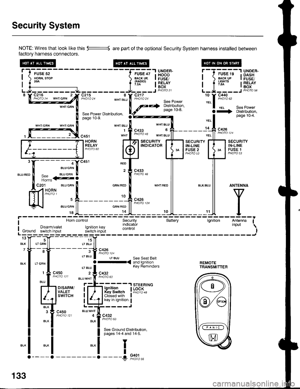
NOTE: Wires that look like this --::= are part of the optional Security System harness installed betlveen
factory harness connectors.
!-l-'*;;--
-----f.-u'?;l
HBB'J' !--T-'u-"-"-13X3"'*-| ) Ho-BN.srop ) B..l\-cj^qp I FUSE/ | ) Flg!!!p I FusE,| 1."^ | lTl"'", I RELAY I a ;'lx'" I RELAY| {--------------- l'* | Box I l -^ lBox
LJ--------.J4---------9----JP4oto21 L-Ja----JPHoro,3"\W27**^ -"hlT'jZn8:,*[:*ift :.1::t*'
seepowerpage 1o-8. a+ Distributjon,See Power Dislribulion. rZ)z----- I page 104.page 10-9.
''"' "t' 1.*"
*', "r:l-
- - - - - -,C **
, f]3,"0u, "1,f ";"3" *",J"11-------;'ff ;;;"
[F=]F;"#,.. kfl
t"ffBr+T'
EilHr{" E
mli
"."".:X-:-S]""'
"T['*-
ll ll
ffi'-"*FL_____r*F_*l
l^y^
c4s1 wnr I t"o'o 'o tn"r ".u | | ".. | | *n' ' '
i Horn control Security Battery lgnition Antenna Ia Horn control Security Battery lgnilion Antenna I
I Drsarm/varet rq indicator 'nPut \
: Ground switch input r.JllXi'lJ;,L control I! Ground switch input s'ivitcn inprlt IL------; ------Jtoy--T|f- -----,;]1
BrK ll rrGRNll LrBLU ll7 Yi- -;-lt- - - - - - -;-:t c426
"-l ,"":l :::lb.i[ri?n'a'fl:. r..rn?.,n| 'eru I Kev Reminders rRANsMlrrER
r
c4so z:L cqgz
:l-il*
",, I
ttu' . *'*'i'f, F;l'o"
rh d.,til i;-fr H{jfJ. I i{",;::*
Ed'"""" LliCir'l':i
":it*t*'
"t--,i[;""
I See Ground Distributron.I pages 14-4 and 14 5.
-.1
I
I
"..1
133
G401
Page 1555 of 1681
Hatch Opener
7WHT/GRN
WHY/GRN
;il
T(
t
IY
Ia
I
a
FUSE 1(POWERDooa Locx)
c504
wHT,cFN See Power---r> Distribution,page 10-2.
c516(ln'line connector;may not be presentin all cars.
UNDER-DASHFUSE/RELAYBOX
See GroundDistribution,page 14-7.
cs27
c758
c758
BLUAA/HT
cs30
c524HATCHOPENERswtTcH
HATCHOPENERACTUATOR
"":il;;,,,
Orr-<
*"L#
BLUAA/HT
134
Page 1558 of 1681
lnterlock System
- How the Circuit Works
Key Interlock
Battery voltage is supplied at all times through f use
33 to the key interlock switch. When the key is in
the ignition, battery voltage is supplied to the key
intedock solenoid and the key interlock circuit in the
interlock control unit. When the A/T gear position
switch is in PABK, ground is provided to the key
interlock circuit. This removes ground from the
interlock solenoid, the solenoid is deenergized, and
the key can be removed from the ignition.
Shift Position Interlock
Battery voltage is supplied at all times lrom fuse 52
to the brake switch. With the ignition in ON (ll) or
START (lll), battery voltage is supplied through luse
25 to the shift lock solenoid. When you push the
brake pedal, battery voltage is applied through the
GRN/VVHT wire to the transmission ('98-�99 models)
or powertrain ('00 model) control module (TCM or
PCM). lf, at the same time, you do not push the
accelerator pedal, a low voltage signal is sent
through the RED/BLK wire to the TCM or PCM. The
TCM or PCM then applies voltage through the
WHT/RED wire to the shift lock circuit in the
interlock control unit. lf the A,/T gear position switch
is in the PARK position, the shift lock circuit
provides ground to the shift lock solenoid. The
solenoid is then energized, and the shift lever can
be moved from the PARK Dosition.
Refer to the Service Manual (Section 23, Electrical)
for specific tests or troubleshooting procedures.
138-2