Page 1483 of 1681

Fans (cont'd)
- How the Gircuit Works
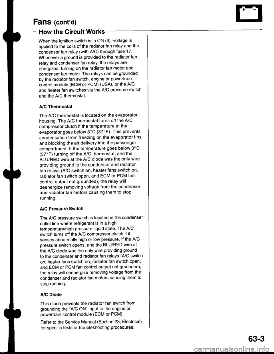
When the ignition switch is in ON (ll), voltage is
applied to the coils of the radiator fan relay and the
condenser fan relay (with A,/C) through fuse 17.
Whenever a ground is provided to the radiator fan
relay and condenser fan relay, the relays are
energized, turning on the radiator fan motor and
condenser fan motor. The relays can be grounded
by the radiator fan switch, engine or powertrain
control module (ECM or PCM) (USA), or the A,/C
and heater lan switches via the A'lC pressure switch
and the A,/C lhermostat.
A,/C Thermostat
The A,/C thermostat is located on the evaporator
housing. The A/C thermostat turns oft the A/C
compressor clutch it the temperature at the
evaporator goes below 3'C (37"F). This prevents
condensalion from freezing on the evaporator fins
and blocking the air delivery into the passenger
compartment. lt the temperature goes below 3'C
(37'F) turning off the A"/C thermostat, and the
BLU/RED wire at the A,/C diode was the only wire
providing ground to the condenser and radiator
fan relays (A,/C switch on, heater fans switch on,
radiator fan switch open, and ECM or PCM fan
controi output not grounded), the relay will
deenergize removing voltage from the condenser
and radiator fan motors causing them to stop
running.
A,/C Pressure Switch
The AJC oressure switch is located in the condenser
outlet line where refrigerant is in a high
temperature/high pressure liquid state. The A,/C
switch turns off the A,/C compressor clutch if it
senses abnormally high or low pressure. lf the A'lC
pressure switch opens, and the BLU/RED wire at
the A/C diode was the only wire providing ground
to the condenser and radiator fan relays (L/C switch
on, heater fans switch on, radiator lan switch open'
and ECM or PCM fan control output not grounded),
the relay will deenergize removing voltage from the
condenser and radiator fan motors causing them to
stop running.
A./C Diode
This diode orevents the radiator fan switch f rom
grounding the "A'lC ON" input to the engine or
powertrain control module (ECM or PCM).
Refer to the Service Manual (Section 23, Electrical)
for specific tests or troubleshooting procedures.
63-3
Page 1484 of 1681
H"ar ffndow Defogger
---.I UNDER.
i-I,;.;;lH8B'J i
illk.**"llieF iL-Ja---J PEoro 21 L
I DASH
i FUSE/I RELAYI Box
FUSE 16NEAR DEFROSI€B NEIAY7.54
__J PHO|O sA
[._
See Dashand ConsoleLights
Y
"ao,"a" I
--g-,1 cser
c2172
ALK/BLU
'T 9#.'9,,BTruBLU
i
"r'u"au !
@cREARwtNDowDEFOGGERswtTcH
See PowerDistribution,pago 1G6.
c422
UNDER-DASHFUSE/RELAYBOX
S€e GroundDistribution,page 14-5.
:ffilfi$Eijc914Hatchback t1
-----l".* o"nf, L----
f ;fl,:" "onn"",o., -",
I not be presenl in allcars.)
BL|(GRN
I
I
I "u.o
l-lFl REARI .5 | WTNDOW
lll
oEFoGGER
,.^f "tt'
"";',u'," i il{:{'}Fl
l'*'**T.lJ: PHoTo 102
c753
1 REARI WINDOW
I DEFOGGERIJ BLIIGRNc771
1
BLK/GFN
rII
G?7.1 L
".of,or"i:
BU( ltGFNA c516
'." ! 1]ll'.llGRN ll pre6e
2 J C525BL|! ll P,lorc
neof czss
msi
lllo'Y c771
BLK
BLK
cs16(ln-line connectorlmay not bepresent in allcars.)
"..1
t
REARwtNDow
swlTcHLIGT'Toila_
ONINDICA.TOR
ry$:F*
::";,=.4
-
: :
-L[; - -
T
- - - - -
I
iiffit]lffi**'
BLKBLU
64
Page 1485 of 1681
- How the Circuit Works
Voltage is applied at all times through f use 50 to
the rear window defogger relay. With the ignition
swrtch in ON (ll), voltage is applied through luse
16 to the rear window defogger relay and the
defogger ON indicator.
When you turn the rear window defogger switch to
ON, a path to ground is provided for the rear
window defogger relay and the defogger ON
indicator through the integrated control unit. The
defogger ON indicator light comes on and the rear
window detogger relay contacts close. Voltage is
applied to the detogger grid on the surface of the
rear window and the grid heats the rear window to
remove any fog lrom the glass.
A timer in the integrated control unit will automatically
tum off the defogger atter 20 to 30 minutes.
Refer to the Service Manual (Section 23, Electrical)
for specific tests or troubleshooting procedures.
64-1
Page 1486 of 1681
Integrated Control Unit
see Rear @Window See Wipef/Washer |-'l----
, See Ground' Distribution,
: pase 14-5.
c439
\
\
I
I
t
I
I
WHT/BLU
c438
YEUREO
'r9,x3
*t
Y
SeeCharoinoSyste'm '
--.-,
See Wiper^Vasher
See EngineOil PressureIndicatorLight
rr{See GroundDishibution,page 14-5.
Y
v---!G401
Window See Wioef/Washer f -'l-- - -'l UNDER-HOODDefogser ,-- | I rUS: +e IFUSE/RELAY
I I I llg:-i***'
1'11f ;'.il::ll ^-.wlhcombined utr?i;,'",,
I I I :,8:[il; * o"' ,n", ",o I
!!!i.t@..!.,*,*..
i
-T--
T-[-- :-;:=::::::{----1-- - - - - - - - -
7'
illli{ry;a';:i {iii:*l i
i, tr---I".!,.*, i, Ljiri'dt'l-t{-:--h i:tf{#;r {
il
L-
See Rear
Defogger
FUSE 26 ,
FFAWASiIEB ' See power
' page 10-5. 6
RearWindowDefoggerTimerCircult
IntermftentWiper RelayCircult
Englns OilPrgssureIndicatolFlasherClrcuit
70
!..
Page 1488 of 1681

Brake System Indicator Light
- USA
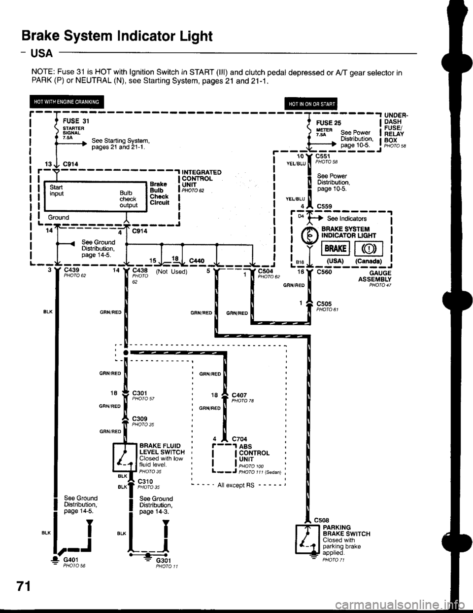
NOTE: Fuse 31 is HOT with lgnition Switch in START (lll) and clutch pedal depressed or A,/T gear selector inPARK (P) or NEUTRAL (N), see Starting System, pages 21 and 21-1.
13 O C914r-V----- -.l INTEGRATED
!r--_.ts__rr,"*" !ERT'"o. | lBtr,i{,fr;
Lj':e--:---J I i;I;:;*;;.;
'of------;-Jclil ! !/e ffiS,'#LT",l< see crouno I I Vr:-:--t r--:=:
ilrF'fi$l ffiiiY@@
-3:".J:iTIS:
I T..T I
Il
! ! YIBRAKEII(DI1
- - - - - - -{L - Js-J=-AL- g1g -.1- - - -{- - i L"jg I _ lyso)_ l"g:f.l_..1
F,o:fo", to IF,flt'3 (Not used) t f,---if r",*%u, tef csoo---.--^g+.rSS
r--T- --- ----r UNDER-
I t FUSE or I ruse zs | 9.4.s!t
i ) 3ffi8" ) 1ry" eeeJo"", ilEiiv
i l3--* ::3"Tii'lH.'ti:i' r il"'li$lr if,g[;,
I | !---r-o v-cl6r-
----.,NrEGRArED i
""lltrt:1'
3ni"iFfi,t-- i !Flif{#r
3i}fi[ | i
"':lln*
, I r:zr=---
*"*'l
.:.:,*,
L--g--3 I' C439
15 -l-lal- el/ t
14 X 91^3,q (Not Used)
; : 816 | IUJA' {LaI|Agtt .J L=g-:__i_-:J
"; " I ll -"," - ll AsslFrr,rBLYGRN/NED I PHO|O4T
c505
GFN/BEO
18
GFN/BEO
GRN/NEO
GFN/FED
18
GFN/FED
I
I
'-l
;.
t
;"x
c301
c309PHOfO 35
c407
4 ^ C704
I GoNTROL
i uNrr
l--J psoro rrr {seaan)
- ' All except RS
See GroundDi$tribution,page 14-5.
PARKINGBRAKE SWITCHClosed withparking brake
Gfound
71
l_ c4ol' PHOIO 56
Page 1489 of 1681

- Canada
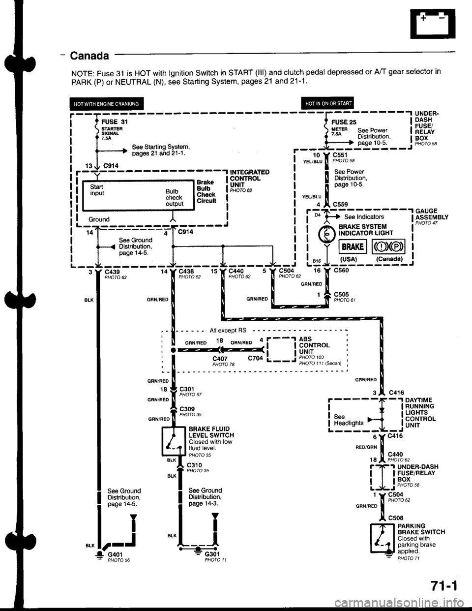
NOTE: Fuse 3l is HOT with lgnition Switch in START (lll) and clutch pedal depressed or A/T gear selector in
PARK (P) or NEUTRAL (N), see Starting System, pages 21 and 21-1.
;;;----
----l;";;-----l
iiSF:'
:'eI[^ ) fg'" see Power | lEiiv
^ seesiarrins sysrem, --- j'[ffi-- j #"1""------'+ pig6 Zr a;d 2r-r. !- - To-v cssr
i r- 3li:Tf8l r---r--_l
| | y tBRAKEil((lJ)(EDt I
L - -r4 - - - - - - - r- - - - - J. - - - - -l - i L= J- g'j'- - S3g1-,
.[Hr*. "IF#1s,, ''f,"c,flls. 'It*'t"i_[
^.^.
*- I o^n".' | | o"n".o L___:;[ s;*,,
lri:
tl
I :-I------ Arrexcept Rs -----------: t
I ii%d#i__jflffi: i I
| """;l
'- ll
I * Vg,l.gl,,
o'""'1.!.
"o'u
i-----f
-1Ri-[iil,'"
I
*"ff;i;-.,.,,"
LEb'r.ji_jb'f,{H*
I l#[i.#rsr
"-"fX;;;;.,
| ].1s*" [Tr P.ls.',ePfiv
|
**1
Lljti';-! see Ground ! See Grouno
'-,oij---------=-*"-,,;---J
i i Anmg"#l''3;' i-
-
l--ffi'Pilr"r-l t ' iiYffi@i
--I -i:"-:-- J-----L---I -i L= J-rs'i-- r"=sr.i
i it"!,8li6l i iq,iit"l :'fl"";'#.,
i
**'?
i
**''; *""*i:;;-
l!."1 IrflBAt['JS*,""
l--J
*^L---l
|y', I Shtrl'l-"
itooo, '---& [+! iPPtreo.: PHoTa s6 PHofall - PHora 71
: | - - --'l uauuc
crourd l ! i t *lA se€ Indicators lfr1s-eyerv
BulbcnecKoutpur
71-1
Page 1490 of 1681
Engine Oil Pressure Indicator Light
lgnition input
L - - - - - *---- ---- --J14 I' Ca14See GroundDistribution,page l4-5.
L------
See Ground
r------- ----__J_--___J
| .---- . to Y cssi
i i vor-mce nEGuLAroR i f,t"t5l|otot ".u"., f
ono'" "
! !i------li il;ffi,r?rl$
i lL--j---.I ! 1*n"'o.u
I L___L___.,i ".,,".u I| 3 lf cile ol csss
I
UNDER-DASHFUSE/RELAYBOX
Ses PovrerDistribution,p,age 1G5.
wHr/BLU | !-;T-------1.;T
c't27 !
-
f+ see IndicatorsPHO|O 36 | I
| ,A low er,rcrxeI { 6l (xL PfiESSURE
s::t.. i Y l.x8i.."i'o'ttr-r
i ,,,1 lr=r,l
L-:g-------
Z J-C.tZz ! H SBe Indicators
GAUGEASSEMBLY
""'.,[r,o_,._
i
eh"#fiFs$.
11
c438
c452
r(RS 4)
YEURED
6
"'"1[,*.,
"rr"ao
I
'-"-[':,':"
l-rlFl ENGTNE OtLI 1 I PRESSURE
l--Il,8yjl?h:^,
Englne Oil Pr6guroIndlcator FlasherClrcull
72
o--< Distrtbution,
Page 1491 of 1681

- How the Circuit Works
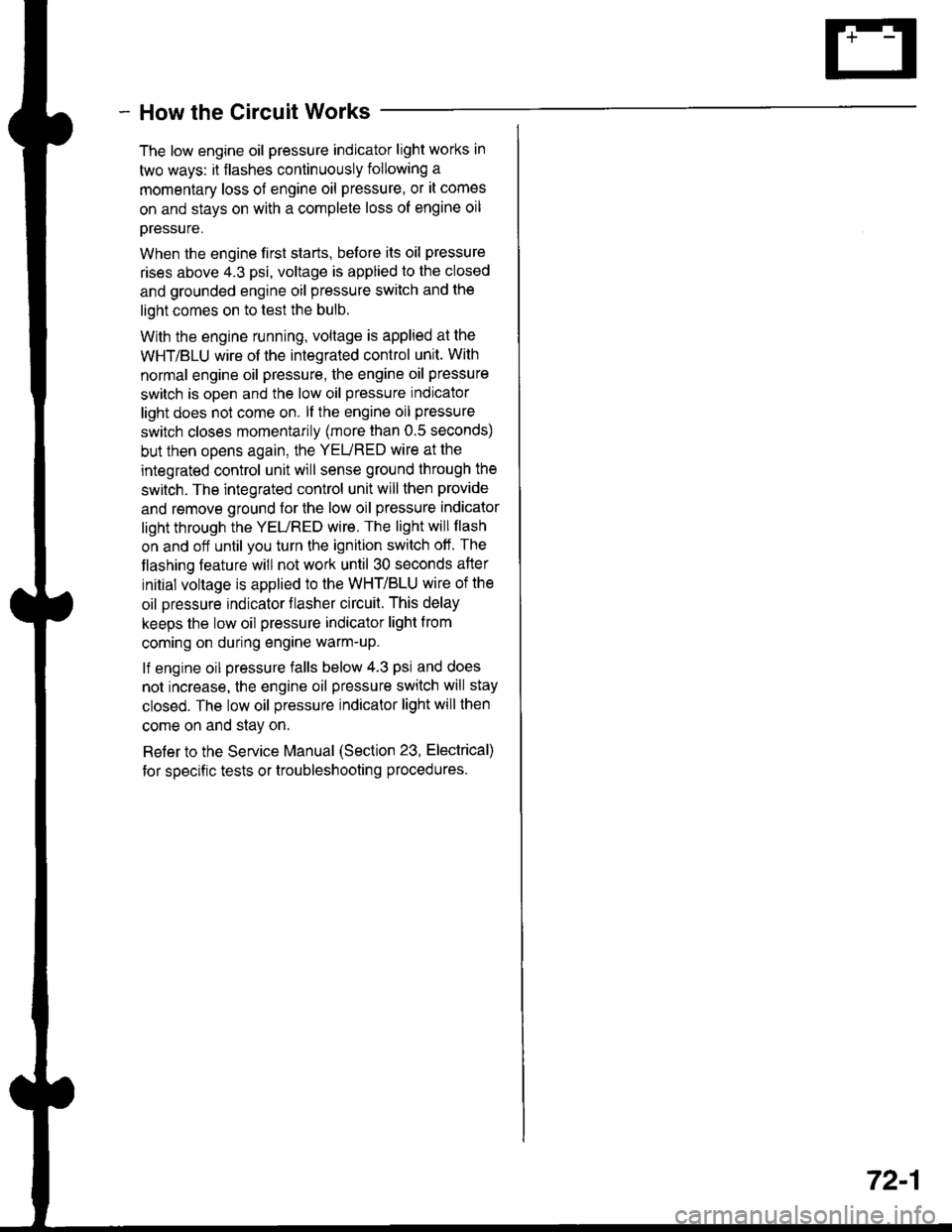
The low engine oil pressure indicator light works in
two ways: il flashes continuously following a
momentary loss of engine oil pressure, or it comes
on and stays on with a complete loss of engine oil
oressure,
When the engine first starts, before its oil pressure
rises above 4.3 psi, voltage is applied to the closed
and grounded engine oil pressure switch and the
light comes on to test the bulb.
With the engine running, voltage is applied at the
WHT/BLU wire of the integrated control unit. With
normal engine oil pressure, the engine oil pressure
switch is open and the low oil pressure indicator
light does not come on. lf the engine oil pressure
switch closes momentarily (more than 0.5 seconds)
but then opens again, the YEURED wire at the
integrated control unit will sense ground through the
switch. The integrated control unit will then provide
and remove ground for the low oil pressure indicator
light through the YEURED wire. The light will flash
on and off until you turn the ignition switch off. The
flashing feature will not work until 30 seconds after
initial voltage is applied to the WHT/BLU wire of the
oil pressure indrcator llasher circuit. This delay
keeps the low oil pressure indicator light from
coming on during engine warm-up.
lf engine oil pressure falls below 4.3 psi and does
not increase, the engine oil pressure switch will stay
closed. The low oil pressure indicator light will then
come on and stay on.
Refer to the Service Manual (Section 23, Electrical)
for specific tests or troubleshooting procedures.
72-1