Page 1492 of 1681
Seat Belt, Lights-on, and lgnition Key Reminders
wHrFEonP,rolo2j
i lll i .._l:["c'xs;"
@,[rsrB", ! | Rtr-r^9,:: I """"1-""
'-----'F--=-'--;fi;'"i
I ffi;'''ffi'' i :seePower
seeHeadriohtf*;ffJiil?l' r i I'l"J:i'J:"t switch. - | BEEPER | | llpage 100-1. | \-7l | | ver-eru I GAUGE
------{ "r'o l-1 . J "r'o i . .I, cuut oss"t"$ElY
! TNTFI:E^TFn I f=tR--
ii
'*:::i"T''*--t
I I ! i
'?tr*aa----'
i t------lI---)t--.&---.L------j i o.o"'u I
i ff{$;{'F1{""0
"l-T-T"*
i
.*r*,
r- - - - - - -
iTs%
-
t
- -
t
- -
f
- - -*"-l
J
- - -
r-
- - -
"'.o ".,
=== = - -
!
Y
I
t
I
See GroundDistribution,page 14-5.
III
i-I+-'.1.1ilg.',8.J39" i-ru;;-
UNDER'DA.H
I rNrEBroR I BOX I
1-l,I:_j
*-"''
i li[::" li[]::'*"
BOXPHOfA 58
i-_I'31_i
,,^sl F,';1",,
| ,1,**",
r----=!i=-'l
F-oc422
----tnilll- -l$H$ffir"
i i'PT:"x':x*
*[-fui'**- i ioiffit.
:i:ltif"i i ilr-zt
! | LeJ-:
LiohtsONinput
Beeper output
Door Key Seat beltswitch switch swiichinput input input
73
II
Page 1494 of 1681
- How the Circuit Works
Do not smoke while working on the fuel system.
Keep open flame away from the work area. Drain
fuel only into an approved container.
A thermistor is mounted in the fuel tank unit. When
the thermistor is cool, its resistance is very high.
When the thermistor is warm, its resistance
decreases. Fuel in the fuel tank transfers heat away
from the thermislor last enough to keep it cool so
the thermistor's resistance stays high and the low
fuel indicator lighl does not come on. When the fuel
level drops below about 2.2 gallons, the thermistor
is no longer immersed in fuel. Without the fuel to
cool it, the thermistor's resistance decreases,
allowing current to flow through the low fuel
indicator light and the thermistor to ground, and lhe
low fuel indicator light comes on.
Refer to the Service Manual (Section 23, Electrical)
for specific tests or troubleshooting procedures.
74-1
Page 1496 of 1681
See Dash andConsole Lights
GAUGEASSEMBLY
(cont'd)
80-1
CRUISEcor{TRoL'NDICATONLIGHT
TcrurFlI cofnot I
r.ow ENGTNE IOIL PRESSURE IINDICATORLIGH'
I\YrlL:J
See Gauges,I'lT Gear PositionIndicator
"ff
I
See CrlControl
See GroundDistribution,page 14'5.
Y
I
.-t
G401PHO|O 56
T
li
'"1
See PGM'FI See Engineoil PressurelndicalorLight
* = '98-'�99 Modets
SeeMaintenanceReminderLight
\. I [,'d['*"' I il]i"fl".,B* I
i,1_* =i^ .l
'*f----l- :{
Page 1503 of 1681
A/T Gear Position Indicator
UNDER.DASHFUSE/RELAYBOXPHOTA 58
POWERTRAIN TRANSMISSION
I D4. I coNrRoL | tr. lcoNrRoL
L$"r:j HS}H Lrulij
frBfii:'
*-1.'-f,"*' *,::-f,"*'c551
Ses PowatDislribution,page 10-5.
See Dashand ConsoleLights
'00 l4odel
't0
:ql
'98'�99 [4odels
c430
c558
410S€e Gaug€s,lndicators
See Dashand ConsolaLights
GAUGEASSEMBLY
A/r IGsa. IPoEltlon :lrdlcator I
I
I
I
I
I
I
I-t**r*",!
Indicdo6 |
I
I
L---ac9
c559
* = 98-99Models
Sgs GroundDistributon,pages 'l4{
and 1+5.
4
GRNAVHT
(" 5)
SeelnterlockSystem
Yi GBN/",i,ll I wHr
'12
GFNA!/HT
c413BLK1
BLK
V
T
I
I- - --a_ G40 t= PHOTO 56a
See PowerDiBaibution.
89
Page 1504 of 1681

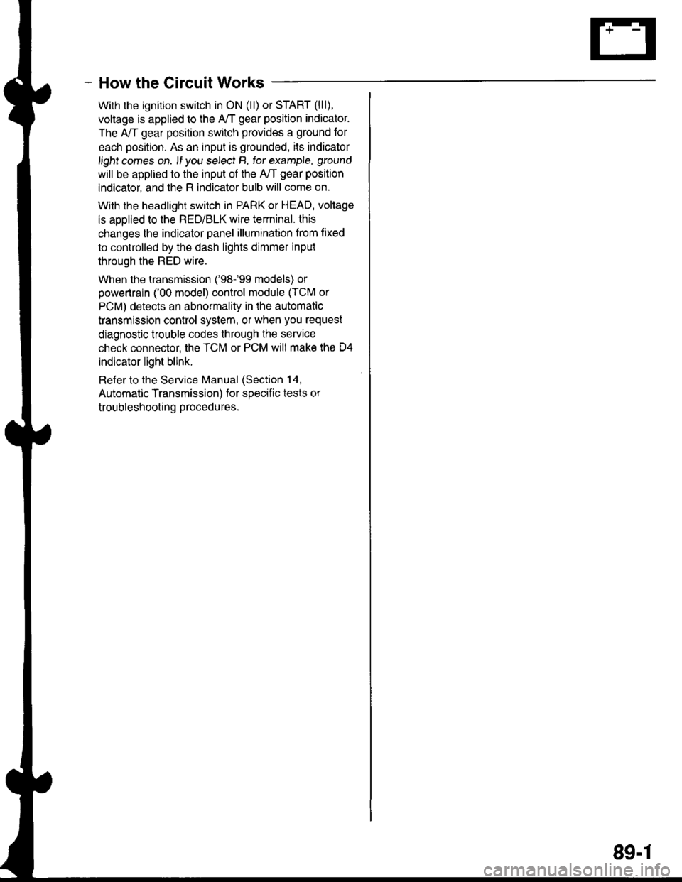
- How the Circuit Works
With the ignition switch in ON (ll) or START (lll),
voltage is applied to the A,/T gear position indicator.
The A,/T gear position switch provides a ground for
each position. As an input is grounded, ils indicator
light comes on. lf you se,ecl B, tor example, ground
will be applied to the input of the A,/T gear position
indicator, and the R indicator bulb will come on.
With the headlight switch in PARK or HEAD, voltage
is applied to the RED/BLK wire terminal. this
changes the indicator panel illumination from lixed
to controlled by the dash lights dimmer inpul
through the RED wire.
When the lransmission ('98.�99 models) or
powertrain ('00 model) control module (TCM or
PCM) detects an abnormality in the automatic
transmission control system, or when you request
diagnostic trouble codes through the service
check connector, the TCM or PCM will make lhe D4
indicator light blink.
Refer to the Service Manual (Section 14,
Automatic Transmission) for soecific tests or
troubleshooting procedures.
89-1
Page 1506 of 1681
tlIr
UNDER-DASHFUSE/RELAYBOXPHO|O 58
c3084GFN/BLK
MOTOR l,enoro ta ).t
t:wrND. l:SHIELD i,WIPER | '
;,-T;t ",,. j i:l Dr
BLU, f
- - - - -
-- ;1lt-
- --.Y
;;".*.- u Y "%93,,aLul "'uio*l ".* | iii.ilii;'
'u A------ jxtIA csozpage 1+3.
r*s31f-----;;;[;'%%- | I *.1ar.ul u""Ti L__j ""'
i,iiirr | 9.oflPl
t:
{-;-- I Z-;"' h''p"" !S?#Rl; i a:wis:h€r t !!lILo-N
)t"-*-d-;'
---
*'d '*'j l$if iy'f'F15" ! lil i i
.-----J-------_-_-_-_-J-^-.----, rs I csoz i:l :'[----- -
",1
*' tnser
[
ilb%s'
il
Mii
""o""1 ffii513:- ".-u'*'f ii
/----;L----::-----------:--------l---f;,-';:--:-V-'q
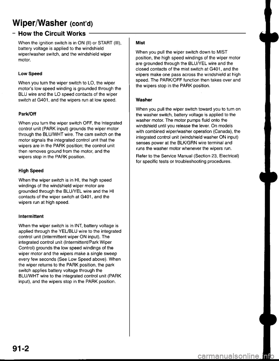
Wiperffasher (contd)
- How the Circuit Works
When the ignition switch is in ON (ll) or START (lll),
battery voltage is applied to lhe windshield
wiper/washer switch, and the windshield wiper
motor.
Low Speed
When you turn the wiper switch to LO, the wiper
motor's low speed winding is grounded through the
BLU wire and the LO speed contacts of the wiper
switch at G401, and the wipers run at low speed.
ParUOfi
When you turn the wiper switch OFF, the integrated
control unit (PARK input) grounds the wiper motor
through the BLUMHT wire. The cam switch on the
motor signals the integrated control unit that the
wipers are in the PARK position; the control unit
then removes ground from the motor, and the
wipers stop in the PARK position.
High Speed
When the wiper switch is in Hl, the high speed
windings ol the windshield wiper motor are
grounded through the BLUI/EL wire and the Hl
contacts of the wiper switch at G401 , and the
wipers run at high speed.
Intermittent
When the wiper switch is in lNT, battery voltage is
applied through the YEUBLU wire to the integrated
control unit (lntermittent wiper ON input). The
integrated control unit (lntermittenvPark Wiper
Control) grounds the low speed windings of the
wiper motor and the wipers make a single sweep
every few seconds (See Low Speed above). When
the wiper returns to the PARK position, the park
switch applies battery voltage through the
BLUMHT wire to the integrated control unit (PARK
input), and the wipers stop in the PARK position.
91-2
Mist
When you pull the wiper switch down to MIST
position, the high speed windings of the wiper motor
are grounded through the BLU//EL wire and the
closed contacts of the mist switch at G401, and the
wipers make one pass across the windshield at high
speed. The PABKOFF tunction then takes over and
the wrpers stop in the PARK position.
Washer
When you pull the wiper switch toward you to turn on
the washer switch, battery voltage is applied to the
washer motor. The motor pumps fluid onto the
windshield until you release the lever. On models
with combined wiper/washer operation (Canada), the
integrated control unit (windshield washer ON input)
senses power al the BLI(GRN wire terminal and
runs the washer motor whenever the wioers run.
Reter to the Service irlanual (Section 23, Electrical)
for specific tests or troubleshooting procedures.
Page 1508 of 1681
Rear WiperMasher
UNDER.DASHFUSE/RELAYBOXPHO|A 58
I
GRNAiTHf
c442:- - ---J
ALK
LT GFN/BLK
lT GFN/BLK
c504
GFN/AIK
c5r6(ln-line connectort maynot be present in all cars.)GRN/BLK
GFN/6LK
1
GRN/BLK
GFN
5GFN
1
LT GFN/BLK
4
c526
c755
LT GFN/BLK
REARwtNDowWIPERMOTOR
GFN
GFN
GRN
c526
c516
2
8LK
(ln-line connector; maynot be present in all cars.)
c422PHafo 56
c435PHOTO 48
Or-(
I
!
See GroundOistribution,page 1+7.
LTGRN/BIK
4G751
.I COMBINATTONRear I WIPERwtndow : swtTcHwiper/ |Washer ISwltch !I
BLU
BLU/BLK
8(RS 12)
BLU/6LK
2LT GRN/BLK
c302
c3r8
REARwrNDowWASHERMOTOR
3
BLK
c435
See Ground Distribution,page 'l4-5.See GroundDiskibution,page 1+3.
BLK?f *'u "* Y f
L_______l'------=,cgot.<
PHA|O 11
92