Page 1561 of 1681

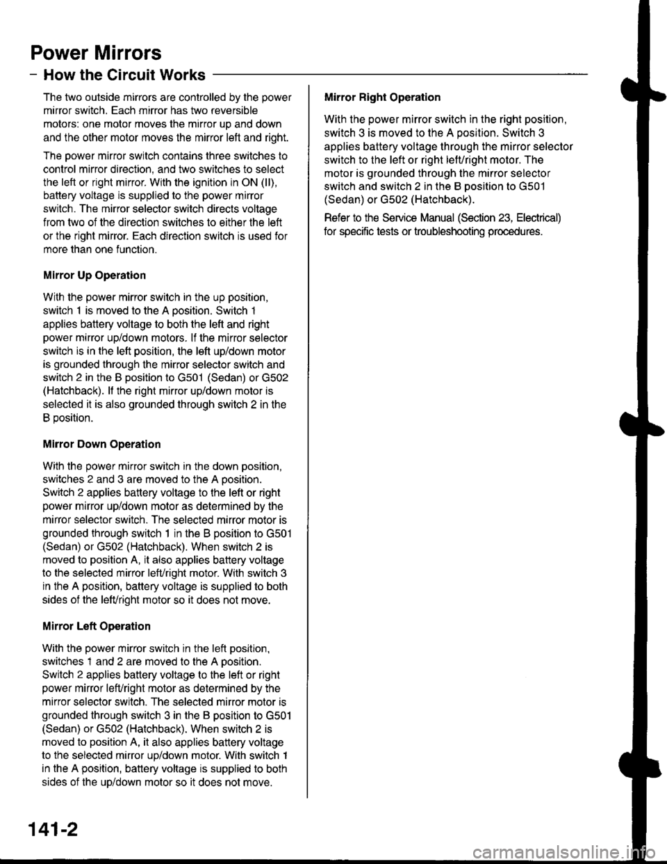
Power Mirrors
- How the Gircuit Works
The two outside mirrors are controlled by the power
minor switch. Each mirror has two reversible
motors: one motor moves the mirror uo and down
and the other motor moves the mirror left and right.
The oower mirror switch contains three switches lo
control mirror direction, and two switches to select
the left or right mirror. With the ignition in ON (ll),
battery voltage is supplied to the power mirror
switch. The mirror selector switch directs voltage
from two of the direction switches to either the left
or the right minor. Each direction switch is used for
more than one function.
Mirror Up Operation
With the power mirror switch in the up position,
switch 1 is moved to the A oosition. Switch 1
applies battery voltage to both the left and right
power mirror up/down motors. lf the mirror selector
switch is in the left position, the left up/down motor
is grounded through the mirror selector switch and
switch 2 in the B position to G501 (Sedan) or G502
(Hatchback). lf the right mirror up/down motor is
selected il is also grounded through switch 2 in the
B position.
Mirror Down Operation
With the power mirror switch in the down position,
switches 2 and 3 are moved to the A position.
Switch 2 applies battery voltage to the left or right
power mirror up/down motor as determined by the
mirror selector switch. The selected mirror motor is
grounded through switch I in the B position to G501
(Sedan) or G502 (Hatchback). When switch 2 is
moved to position A, it also applies battery voltage
to the selected mirror lefyright motor. With switch 3
in the A position, battery voltage is supplied to both
sides of the leruright motor so it does not move.
Mirror Left Operation
With the power mirror switch in the left position,
switches 1 and ? ate moved to the A oosition.
Switch 2 applies battery voltage to the left or right
power mirror lefvright motor as determined by the
mirror selector switch. The selected mirror motor is
grounded through switch 3 in the B position to G501
(Sedan) or G502 (Hatchback). When switch 2 is
moved to position A, it also applies battery voltage
to the selected mirror up/down molor. With switch 1
in the A position, battery voltage is supplied to both
sides of the uD/down motor so it does not move.
Mirror Right Operation
With the power mirror switch in the right position,
switch 3 is moved to the A position. Switch 3
applies battery voltage through the mirror selector
switch to the left or right lefvright motor. The
motor is grounded through the mirror selector
switch and switch 2 in the B oosition to G501
(Sedan) or G502 (Hatchback).
Refer to the Service Manual (Section 23, Electrical)
for specific tests or troubleshooting procedures.
141-2
Page 1563 of 1681
EI
r__1 cD r--1 co
I IPLAYER | | CHANGER
ll ll
;r ;r
STEREORAOTO/CASSETTEPLAYER
with OptionalCD ChangerWith OptionalCD Player
c516 :(ln-line connector;may not be present '
in allcars.) :
1
.r"-+-Ground
150-1
Page 1564 of 1681
Power Antenna
9_5^s,1 -^ oPloNCONNECTOR(ACC)
c505
UNDER.DASHFUSE/RELAYBOXPHOTO 58
ifsEii'-----'1NAD'O
UNDER-DASHFUSEiRELAYBOXPHOTA 58
STEREORADIO/CASSETTEPLAYER
UNDER-HOODFUSE/RELAYBOX
T--;;--+--{> Distribution,
I__i1':__
f
r*.,
I"."
I
I
I
YEUGBN
2
YEUGFN
l"^"
@.
WHT/BEO
1c5tI
POWERANTENNAMOTOR
ANTENNALEAO
er* I
FJ
c518
See GroundDistribution,page 14-7.
iT;;-r
L-tr:-::i6 Y C217
s A c566
i-I*-------t
I r-i- |
LI-t.-*-3E&"{3::J
151
arrxa
Page 1565 of 1681
Clock
I
I
8(RS 7)
WHT/BLU
UNDER-HOODruse lz I FUSE/RELAY
lragr-lle I Pg^I^ ^
{f*'o, a PHafo 21
c2'17
aaaQ
c452
aaaa)'
"-,,[r*"
nnT,i"".'-.)
I
Y
See PowarDistribution,page 10-5.
r--I------1 UNDER-DASHI f FUSE2S I FUSE,RELAY
a J y5t* a"';L,,
| | See Power l
r f+ ?:"i:q*t:"' IL--9,-.-=:-:J10 Y C551
8
WHT/BLU
WHT/BLU
See PowerDistribution,page 10-8.
WHT/BLU
See PowerDistribution,page 10-8.
See Dash andConsole Lights
T
I
"ao,"a* f
--J"*'
CLOCKBattery(memoryJlgnitionDimminginput
Ground
1 Y C561
',54
Page 1596 of 1681

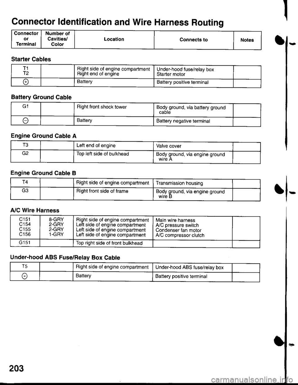
Connector ldentification and Wire Harness Routing
Connector
OT
Terminal
Number of
Cavities/
Color
LocationConnecls toNotesI
fl-
Starter Cables
T1
T2Right side of engine compartmentRight end of engineUnder-hood fuse/relav boxStarter motor
oBatteryBattery positive terminal
Battery Ground Cable
lRight front shock towerBodyground, via battery ground
ABatteryBattery negative terminal
Engine Ground Cable A
T3Left end of engineValve cover
Top left side ol bulkheadBody ground, via engine ground
Engine Ground Cable B
T4Right side of engine compartmentTransmission housing
Right front side of trameBody ground, via engine ground
wrre b
A,/C Wire Harness
Under-hood ABS Fuse/Relay Box Cable
203
c151
c'154utSc
u tco
8-GRY
2-GRY
2-GRY
1-GRY
Right side ol engine compartmentLeft side of engine compartmentLeft srde of engine compartmentLeft side of engine compartment
Main wire harness
A'lC pressure switch
Condenser tan motorA,/C compressor clutch
lrlclTop right side ot front bulkhead
T5Right side of engine compartmentUnderhood ABS fuse/relav box
\,BatteryBattery positive terminal
Page 1597 of 1681
)-
)-
UNDER-HOOD ABSFUSE/RELAY BOX CABLE
BATTERY GROUNDCABLE
ENGINE GROUNDCABLE B
A/C WIRE HARNESS
T3
ENGINE GROUNDCABLE A
)t
203-1
Page 1598 of 1681

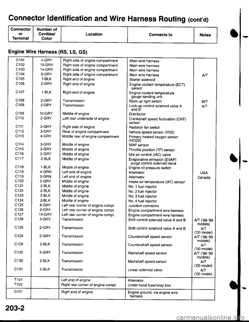
Connector ldentification and Wire Harness Routing (cont,d)
Connector
or
Terminal
Number ot
Cavities/
Color
LocationConnects toNotes
Engine Wire Harness (RS, LS, GS)
c101
c102
c103
c104
c105
c106
c 107
c108
c108
c'1 09
c110
c111
cl12
c113
c'114
c115
c116
c117
c118
c119
c1 19
c120
c121
c122
c123
c124
cl25
cl26
c127
Ql28
c128
c129
c 129
c130
c'l30
c131
4.GRY
1O.GRY
14-GRY
6-GRY
1.BLK
2-GRY
,1-BLK
2-GRY
2.GRY
1O-GRY
2-GRY
2-GRY
3-GRY
4-GRY
3-GRY
3-GRY
2-GRY
2.BLK
.1-BLK
4-GRN
3-GRN
2-GRY
2.BLK
2-BLK
2-BLK
2.BLK
8-GRY
2-GRY
14-GRY
3-GRY
2.GRY
2.GRY
2-BLK
3-GRY
2-BLK
2-BLK
Right side of engine compartment
Right side of engine compartment
Right side ot engine compartment
Right side of engine compartment
Right end of engine
Right end of engine
Right end of engine
Transmission
Transmission
lvliddle ol engine
Lett rear underside of engine
Right side ol engine
Rear of engine compartment
Middle rear ol engine compartment
Middle ol engine
Middle of engine
Middle ol engine
l\4iddle of engine
Middle of engine
Left end ot engine
Lett end of engine
Middle of engine
N,liddle ol engine
Middle of engine
Middle of engine
Middle of engine
Left rear corner of engine compt.
Lelt rear corner of engine compt.
Left rear corner of engine compt.
Transmission
Transmission
Transmission
Transmission
Transmission
Transmission
Transmission
Main wire harness
Main wire harness
Main wire harness
Main wire harness
Starter solenoid
Engine coolant temperature (ECT)sensor
Engine coolant temperaturegauge sending unit
Back-up light switch
Lock-up control solenoid valve Aand B
Distributor
Crankshaft speed fluctuation (CKF)sensor
Radiator fan switch
Vehicle speed sensor (VSS)
Primary heated oxvoen sensor(H02s)
MAP sensor
Throttle position (TP) sensor
ldle air control (lAC) valve
Evaporative emission (EVAP)purge control solenoid valve
Engine oil pressure switch
Alternator
Alternator
Intake air temperature (lAT) sensor
No. I fuel injector
No. 2 fuel injector
No. 3 tuel injector
No. 4 fuel injector
Junction connector
Engine compartment wire harness
Engine compartment wire harness
Shitt control solenoid valve A and B
Shift control solenoid valve A and B
Countershaft speed sensor
Countershatt speed sensor
lvtainshatt speed sensor
Mainshaft speed sensor
Linear solenoid valve
NT
[/VT
A"/T
USA
Canada
A/T (98199models)
AIT('00 model)
A,/T ('98-'�99models)
('00 model)
A,/T f98-'99models)
Atf('00 model)
AN('00 model)
T101
T102
Left end of engine
Right rear corner of engine compt.
Alternator
Under-hood fuse/relay box
G'101Right end ot engineEngine ground, via engine wirenarness
o
I
203-2
Page 1600 of 1681

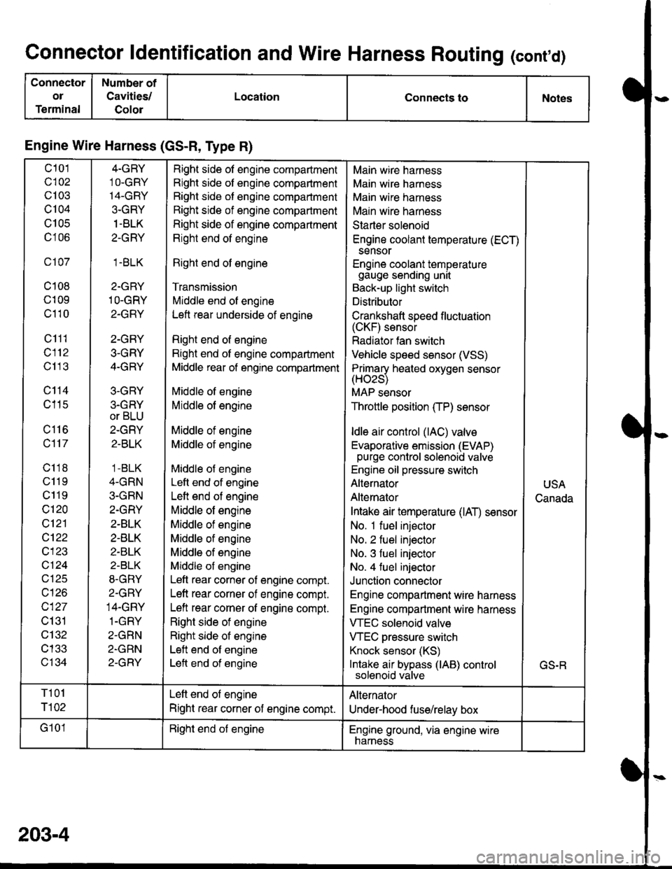
Connector ldentification and Wire Harness Routing (conrd)
Connector
ol
Terminal
Number of
Cavities/
Golor
LocationConnects toNotes
Engine Wire Harness (GS-R, Type R)
c101
c102
c103
c104
U IUC
c106
c107
c108
c109
c110
c111
c112
c113
c114
c115
c116
c117
c118
c11 9
c119
c120
c121
cl22
c123
vtzl
wt10
c127
c131
c132
c133
c134
4-GRY
1O-GRY'I4-GRY
3-GRY
1 -BLK
2-GRY
1.BLK
2-GRY
1O-GRY
2-GRY
2-GRY
3-GRY
4-GRY
3-GRY
3.GRY
or BLU
2-GRY
2-BLK
1 -BLK
4-GRN
3-GRN
2.GRY
2-BLK
2-BLK
2-BLK
2-BLK
8-GRY
2.GRY
14-GRY
1-GRY
2-GRN
2-GRN
2-GRY
Right side of engine compartment
Right side of engine compartment
Bight side of engine compartment
Right side of engine compartment
Right side of engine compartment
Right end of engine
Right end of engine
Transmission
Middle end of engine
Left rear underside of engine
Right end of engine
Right end of engine compartment
Middle rear of engine compartment
Middle of engine
Middle of engine
Middle of engine
Middle of engine
Middle of engine
Left end of engine
Left end of engine
Middle of engine
Middle of engine
Middle of engine
Middle of engine
Middle of engine
Left rear corner of engine compt.
Left rear corner of engine compt.
Left rear corner of engine compt.
Right side of engine
Right side of engine
Left end of engine
Left end of engine
Main wire harness
Main wire harness
Main wire harness
Main wire harness
Starter solenoid
Engine coolant temperature (ECT)
sensor
Engine coolant temperaturegauge sending unit
Back-up light switch
Distributor
Crankshaft speed f luctuation(CKF) sensor
Radiator fan switch
Vehicle speed sensor (VSS)
Primarv heated oxvoen sensor(Hozs)
MAP sensor
Throttle position (TP) sensor
ldle air control (lAC) valve
Evaporative emission (EVAP)purge control solenoid valve
Engine oil pressure switch
Alternator
Alternator
Intake air temperature (lAT) sensor
No. 1 fuel injector
No. 2 fuel injector
No. 3 fuel injector
No. 4 fuel injector
Junction connector
Engine compartment wire harness
Engine compartment wire harness
VTEC solenoid valve
VTEC pressure switch
Knock sensor (KS)
Intake air bypass (lAB) controlsolenoid valve
USA
Canada
GS.R
T101
r102
Left end of engine
Right rear corner of engine compt.
Alternator
Under-hood fuse/relay box
G101Right end of engineEngine ground, via engine wirenarness
203-4