Page 22 of 1807

MT06N-01
D01920
Shift Lever Knob
Upper Console Panel
Shift Lever Boot
RetainerShift Lever Retainer
Shift and Select Lever
Boot No.1
x5
Service Hole
Cover
Starter
Pipe Support Bracket
Service Hole Cover
Ground Cable
Engine Under Cover
Oxygen SensorExhaust Front Pipe Exhaust Tail Pipe Exhaust Center PipePropeller ShaftCrossmember Brace
Heat Insulator Engine Rear
Mounting
Adjusting Washer BushingTransmission Shift Lever
Clutch Release Cylinder
N´m (kgf´cm, ft´lbf)Shift and Select Lever
Boot No.2
Oxygen Sensor Cover
: Specified torqueRear Engine Mounting
Member
� Non-reusable part� Gasket
�
� Gasket
� Gasket��
� Gasket
19 (195, 14)�
72 (730, 53)
12 (120, 9)
79 (805, 58)
49 (500, 36)
19 (195, 14)�
56 (570, 41)
12 (120, 9)
37 (380, 27)
12 (120, 9)
25 (260, 19)13 (135, 10)
39 (400, 29)
5.5 (55, 48 in.´lbf)
13 (130, 9)
13 (130, 9)
5.5 (55, 48 in.´lbf)
Heat Insulator72 (730, 53)
39 (400, 29)
25 (250, 18)19 (195, 14)
19 (195, 14)
7.8 (80, 69 in.´lbf)�
Bushing
�
19 (195, 14)
Normal Roof:
Sport Roof:
58 (590, 43)�
Transmission
Crossmember
Brace
20 (200, 14)
25 (250, 18)
�
58 (590, 43)�
MT-2
- MANUAL TRANSMISSION (V160)MANUAL TRANSMISSION UNIT
1570 Author�: Date�:
1997 SUPRA (RM502U)
MANUAL TRANSMISSION UNIT
COMPONENTS
Page 25 of 1807

Q04136Matchmarks
Q04137
Q04138
Q04341
Q04141
A
B
A
- MANUAL TRANSMISSION (V160)MANUAL TRANSMISSION UNIT
MT-5
1573 Author�: Date�:
1997 SUPRA (RM502U)
15. REMOVE CLUTCH COVER SET BOLT
(a) Remove the 2 bolts and service hole cover.
Torque: 12 N´m (120 kgf´cm, 9 ft´lbf)
(b) Place matchmarks on the flywheel and clutch cover.
(c) Remove the 6 bolts.
Torque: 19 N´m (195 kgf´cm, 14 ft´lbf)
16. JACK UP TRANSMISSION SLIGHTLY
Using a transmission jack, support the transmission.
17. REMOVE REAR ENGINE MOUNTING MEMBER
Remove the 4 nuts, bolts and rear engine mounting member.
Torque:
Nut: 13 N´m (135 kgf´cm, 10 ft´lbf)
Bolt: 25 N´m (260 kgf´cm, 19 ft´lbf)
18. REMOVE STARTER
Lower the engine rear side and remove the 2 bolts and starter.
Torque: 39 N´m (400 kgf´cm, 29 ft´lbf)
19. REMOVE TRANSMISSION
Remove the 5 transmission mounting bolts and transmission
from the engine.
Torque: 72 N´m (730 kgf´cm, 53 ft´lbf)
20. REMOVE SHIFT LEVER RETAINER
Remove the 5 bolts, nut and shift lever retainer from the trans-
mission.
Torque:
Bolt A: 19 N´m (195 kgf´cm, 14 ft´lbf)
Nut B: 25 N´m (250 kgf´cm, 18 ft´lbf)
21. REMOVE ENGINE REAR MOUNTING
Remove the 4 bolts and engine rear mounting from the trans-
mission.
Torque: 25 N´m (250 kgf´cm, 18 ft´lbf)
Page 27 of 1807
MT06R-02
Q04145
Q04146
SST
Q04147
SST
Q04148
SST
Q04149
SST MT-8
- MANUAL TRANSMISSION (V160)OIL SEAL
1576 Author�: Date�:
1997 SUPRA (RM502U)
REPLACEMENT
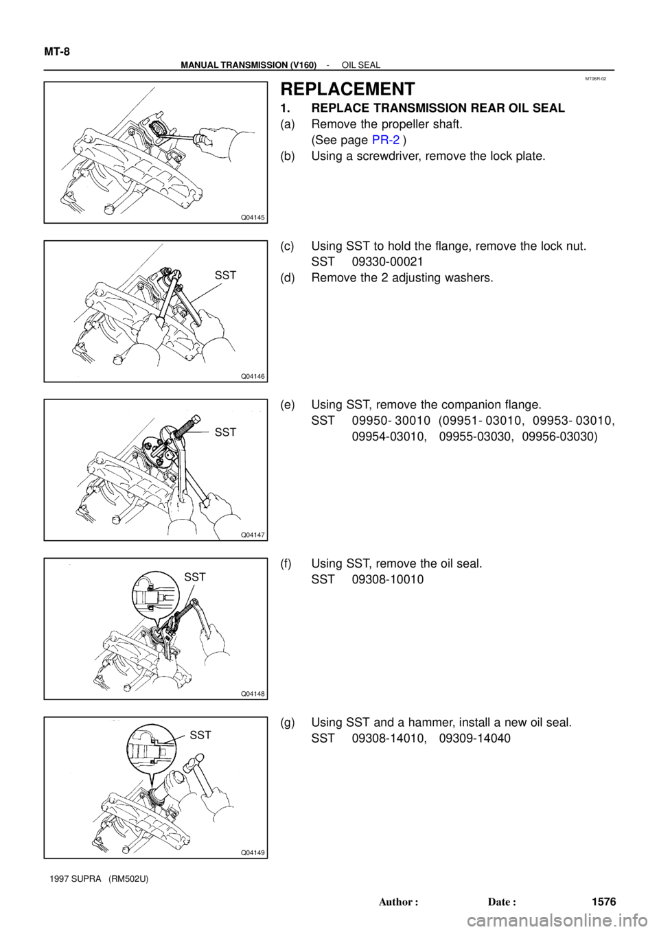
1. REPLACE TRANSMISSION REAR OIL SEAL
(a) Remove the propeller shaft.
(See page PR-2)
(b) Using a screwdriver, remove the lock plate.
(c) Using SST to hold the flange, remove the lock nut.
SST 09330-00021
(d) Remove the 2 adjusting washers.
(e) Using SST, remove the companion flange.
SST 09950- 30010 (09951- 03010, 09953- 03010,
09954-03010, 09955-03030, 09956-03030)
(f) Using SST, remove the oil seal.
SST 09308-10010
(g) Using SST and a hammer, install a new oil seal.
SST 09308-14010, 09309-14040
Page 31 of 1807
PR02H-01
- PROPELLER SHAFTTROUBLESHOOTING
PR-1
1674 Author�: Date�:
1997 SUPRA (RM502U)
TROUBLESHOOTING
PROBLEM SYMPTOMS TABLE
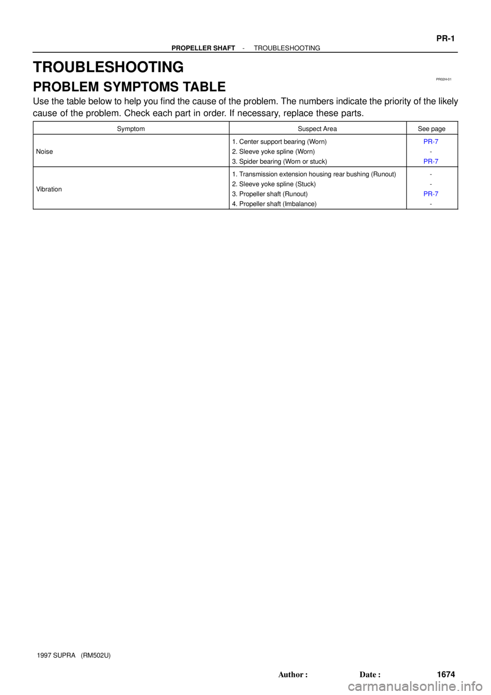
Use the table below to help you find the cause of the problem. The numbers indicate the priority of the likely
cause of the problem. Check each part in order. If necessary, replace these parts.
SymptomSuspect AreaSee page
Noise
1. Center support bearing (Worn)
2. Sleeve yoke spline (Worn)
3. Spider bearing (Worn or stuck)PR-7
-
PR-7
Vibration
1. Transmission extension housing rear bushing (Runout)
2. Sleeve yoke spline (Stuck)
3. Propeller shaft (Runout)
4. Propeller shaft (Imbalance)-
-
PR-7
-
Page 32 of 1807
PR06W-01
R06873
R06872
SST
R07096
120°
Phasemarks
- PROPELLER SHAFTPROPELLER SHAFT ASSEMBLY
PR-1 1
1684 Author�: Date�:
1997 SUPRA (RM502U)
INSTALLATION
1. 2JZ-GE:
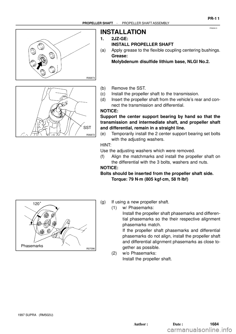
INSTALL PROPELLER SHAFT
(a) Apply grease to the flexible coupling centering bushings.
Grease:
Molybdenum disulfide lithium base, NLGI No.2.
(b) Remove the SST.
(c) Install the propeller shaft to the transmission.
(d) Insert the propeller shaft from the vehicle's rear and con-
nect the transmission and differential.
NOTICE:
Support the center support bearing by hand so that the
transmission and intermediate shaft, and propeller shaft
and differential, remain in a straight line.
(e) Temporarily install the 2 center support bearing set bolts
with the adjusting washers.
HINT:
Use the adjusting washers which were removed.
(f) Align the matchmarks and install the propeller shaft on
the differential with the 3 bolts, washers and nuts.
NOTICE:
Bolts should be inserted from the propeller shaft side.
Torque: 79 N´m (805 kgf´cm, 58 ft´lbf)
(g) If using a new propeller shaft.
(1) w/ Phasemarks:
Install the propeller shaft phasemarks and differen-
tial phasemarks so the their respective alignment
phasemarks match.
If the propeller shaft phasemarks and differential
phasemarks do not align, install the propeller shaft
and differential alignment phasemarks as close to-
gether as possible.
(2) w/o Phasemarks:
Install the propeller shaft.
Page 33 of 1807

R07250
12.5 ± 1 mm (0.492 ± 0.04 in.)
R06873
Z10404
12.5 ± 1 mm (0.492 ± 0.04 in.) PR-12
- PROPELLER SHAFTPROPELLER SHAFT ASSEMBLY
1685 Author�: Date�:
1997 SUPRA (RM502U)
(h) Torque the 2 center support bearing set bolts.
Torque: 49 N´m (500 kgf´cm, 36 ft´lbf)
HINT:
Adjust the center support bearing to keep the dimension, as
shown with the vehicle in the unladen condition.
Under the same condition, check if the center line of the center
support bearing is at right angles to the shaft axial direction.
2. 2JZ-GTE:
INSTALL PROPELLER SHAFT
(a) Apply grease to the flexible coupling centering bushings.
Grease:
Molybdenum disulfide lithium base, NLGI No.1 or
No.2.
(b) Align the matchmarks on the flanges and connect the
flanges with the 4 nuts and washers.
(c) Torque the 4 nuts.
Torque: 56 N´m (570 kgf´cm, 41 ft´lbf)
(d) Insert the propeller shaft from the vehicle's rear and con-
nect the transmission and differential.
NOTICE:
Support the center support bearing by hand so that the
transmission and intermediate shaft, and propeller shaft
and differential, remain in a straight line.
(e) Temporarily install the 2 center support bearing set bolts
with the adjusting washers.
HINT:
Use the adjusting washers which were removed.
(f) Align the matchmarks and install the propeller shaft on
the differential with the 3 bolts, washers and nuts.
NOTICE:
Bolts should be inserted from the propeller shaft side.
Torque: 79 N´m (805 kgf´cm, 58 ft´lbf)
(g) Torque the 2 center support bearing set bolts.
Torque: 49 N´m (500 kgf´cm, 36 ft´lbf)
HINT:
Adjust the center support bearing to keep the dimension, as
shown with the vehicle in the unladen condition.
Under the same condition, check if the center line of the center
support bearing is at right angles to the shaft axial direction.
Page 43 of 1807

R06869Matchmarks
R06867
PR-6
- PROPELLER SHAFTPROPELLER SHAFT ASSEMBLY
1679 Author�: Date�:
1997 SUPRA (RM502U)
(e) Place matchmarks on the transmission companion
flange and propeller shaft flange.
(f) Remove the 4 washers and nuts.
(g) Remove the 2 center support bearing set bolts and ad-
justing washers.
HINT:
Some vehicles are not equipped with and adjusting washer.
NOTICE:
When removing the set bolts, support the center support
bearing by hand so that the transmission and intermediate
shaft, and propeller shaft and differential, remain in a
straight line.
(h) Remove the propeller shaft from the transmission.
(i) Push the rear propeller shaft straight forward to compress
the propeller shaft and pull out the propeller shaft from the
centering pin of the differential.
NOTICE:
Press the propeller shaft straight ahead to keep the trans-
mission and intermediate shaft aligned straight.
(j) Pull the propeller shaft out toward the vehicle's rear.
NOTICE:
The intermediate shaft and propeller shaft should not be
separated.
Page 44 of 1807

PR02K-01
PR0260
R07008
R06873
R01130
R01131
- PROPELLER SHAFTPROPELLER SHAFT ASSEMBLY
PR-7
1680 Author�: Date�:
1997 SUPRA (RM502U)
INSPECTION
1. INSPECT CENTER SUPPORT BEARING
(a) Check if the bearing turns smoothly.
(b) Check for crack in or damage to the cushion.
If the center support bearing is damaged, worn or does not turn
smoothly, replace it.
2. INSPECT FLEXIBLE COUPLINGS
Check for cracks in or damage to rear flexible couplings.
If the flexible coupling is damaged, replace the propeller shaft
assembly.
3. INSPECT FLEXIBLE COUPLING CENTERING BEAR-
ING
Check for damage to the bushing.
If the bushing is damaged, replace the propeller shaft assem-
bly.
4. INSPECT RUNOUT OF INTERMEDIATE SHAFT AND
PROPELLER SHAFT
Maximum runout: 0.8 mm (0.031 in.)
If the runout is greater than the maximum, replace the propeller
shaft assembly.
5. INSPECT SPIDER BEARING
(a) Check if the spider bearing rotates smoothly.
(b) Check if there any play in the spider bearing.
If necessary, replace the propeller shaft assembly.