Page 194 of 1807

N03984
N03985
BE4118
BE4119
BE-38
- BODY ELECTRICALWIPER AND WASHER SYSTEM
2016 Author�: Date�:
1997 SUPRA (RM502U)
(b) Disconnect the negative (-) lead from terminal 3, check
that the motor stops running at the stop position.
If operation is not as specified, replace the motor and relay.
9. INSPECT INTERMITTENT OPERATION
Connect the positive (+) lead from the battery to terminal 1, and
the negative (-) lead to terminal 2 and the motor body, check
that the motor operates intermittently for 9 - 15 seconds.
If operation is not as specified, replace the motor and relay.
10. Front Washer:
INSPECT WASHER MOTOR OPERATION
Connect the positive (+) lead from the battery to terminal 2 and
the negative (-) lead to terminal 1, check that the motor oper-
ates.
NOTICE:
These tests must be performed quickly (within 20 seconds)
to prevent the coil from burning out.
If operation is not as specified, replace the motor.
11. Rear Washer:
INSPECT WASHER MOTOR OPERATION
Connect the positive (+) lead from the battery to terminal 2 and
the negative (-) lead to terminal 3, check that the motor oper-
ates.
NOTICE:
These tests must be performed quickly (within 20 seconds)
to prevent the coil from burning out.
If operation is not as specified, replace the motor.
Page 198 of 1807

I02082I02081
I02080
I02079
I05022
Security Indicator
TRAC OFF Indicator
Low Oil Pressure Warning
Engine Oil Level Warning
Malfunction Indicator
ABS Indicator
No.
Combination Meter (Terminal B2)
ECM
ECM
Low Oil Pressure Warning Switch
Combination Meter (Terminal B4)
TRAC ECU, Traction Solenoid Relay
Ground
Theft Deterrent and Door Lock ECUWire Harness Side
1
2
3
4
5
6
8
9
10
No.Wire Harness Side
GAUGE Fuse
ECU-B Fuse
IGN Fuse
PANEL Fuse
Vehicle Speed Sensor (Terminal 3)
Ground
DOME Fuse
Light Control Rheostat
Combination Meter (Terminal B1)
Generator Terminal
Door Courtesy Switch
Integration Relay (Terminal 9)
Light Failure Sensor Center Airbag Sensor 1
2
3
4
5
6
8
107
11
12
14
15
16
18GAUGE Fuse
PPS ECU, Cruise Control ECU, ECM OD/TRIP
Meter
Open Door Warning
Seat Belt Warning
SRS Warning 8
6 5
3
4
110
2 9
7
10
5
14
18
12
16
15
114
6
1
8
3
2Air Conditioning Amplifier Telltale Light LH:
Telltale Light RH:
Rear Light Warning
Discharge Warning BE-42
- BODY ELECTRICALCOMBINATION METER
2020 Author�: Date�:
1997 SUPRA (RM502U)
2. TELLTALE LIGHT:
Page 211 of 1807
Z18235
Outer Rear View Mirror LH
Mirror DefoggerA/C Control Panel Assembly
Defogger Switch
Outer Rear View Mirror RH
Mirror Defogger
Rear Window Defogger Defogger Relay R/B No.4
MIR-HTR Fuse DEFOG Fuse GAUGE Fuse J/B No.1
�
�
� �
� �
�
BE0EC-01
- BODY ELECTRICALDEFOGGER SYSTEM
BE-55
2033 Author�: Date�:
1997 SUPRA (RM502U)
DEFOGGER SYSTEM
LOCATION
Page 223 of 1807
Z18238
Outer Rear View Mirror LHOuter Rear View Mirror RH
Mirror Defogger Mirror Motor
Mirror Switch
PAD No.2 Fuse�
J/B No.1�
�
BE0EI-01
- BODY ELECTRICALPOWER MIRROR CONTROL SYSTEM
BE-67
2045 Author�: Date�:
1997 SUPRA (RM502U)
POWER MIRROR CONTROL SYSTEM
LOCATION
Page 256 of 1807
BE0ER-01
Z14749
Insert
Front
Teeth on
Cable
BE4674
Twist BE-100
- BODY ELECTRICALANTENNA
2078 Author�: Date�:
1997 SUPRA (RM502U)
INSTALLATION
INSTALL ANTENNA ROD
(a) Insert the cable of the rod until it reaches the bottom.
HINT:
�When inserting the cable, the teeth on the cable must face
toward the rear of the vehicle.
�Insert the cable approx. 400 mm.
(b) Wind the cable to retract the rod by turning the ignition
switch to ºLOCKº position.
HINT:
�If the ignition switch is already in ºLOCKº position, do step
1 (c) first, then turn the ignition switch to ºACCº position.
�In case the cable is not wound, twist it as shown in the il-
lustration.
�Even if the rod has not retracted fully, install the antenna
nut and inspect the antenna rod operation. It will finally re-
tract fully.
(c) Inspect the antenna rod operation by pushing the radio
wave band select buttons.
Page 263 of 1807
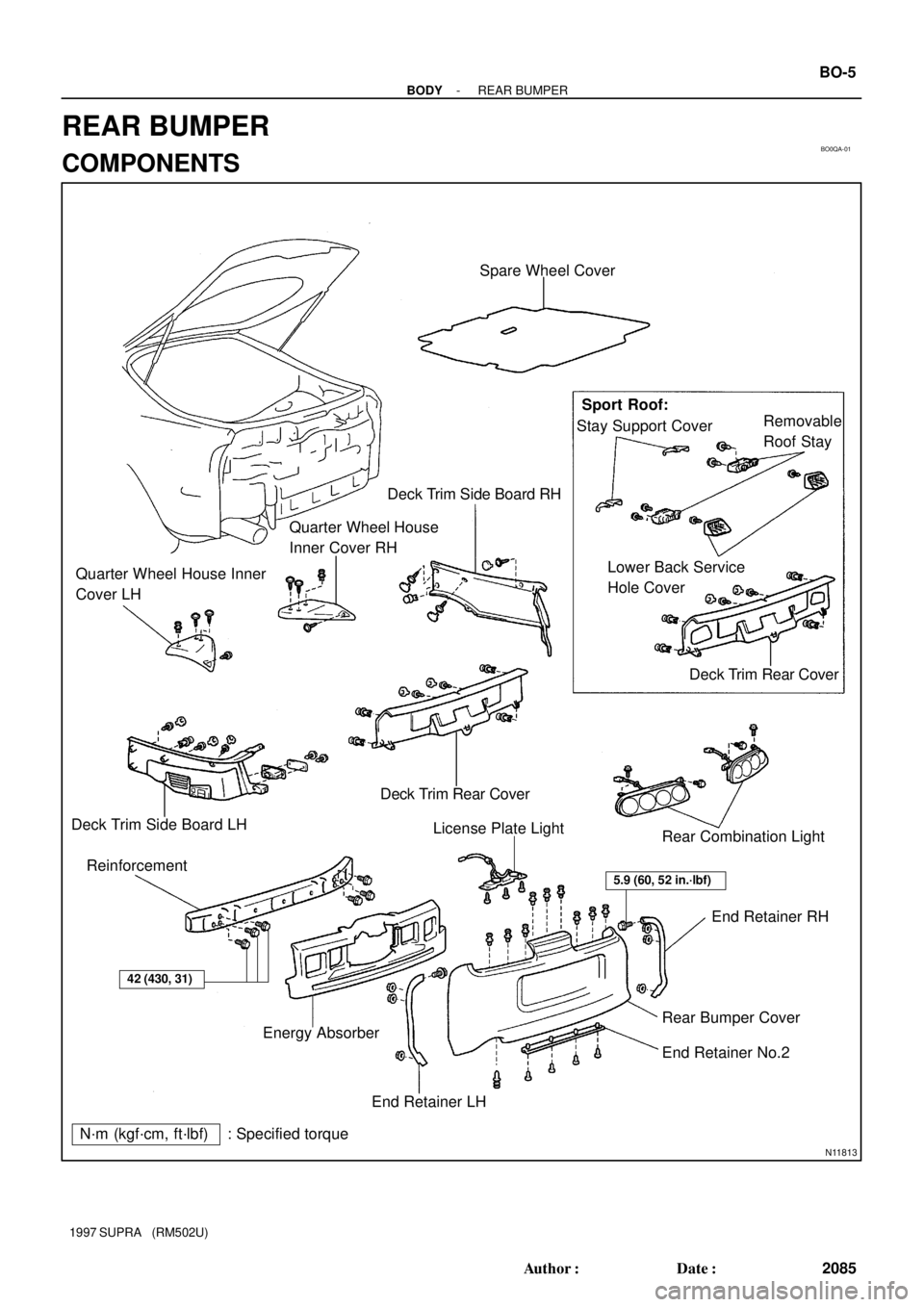
BO0QA-01
N11813
Spare Wheel Cover
Deck Trim Side Board RH
Quarter Wheel House
Inner Cover RH
Quarter Wheel House Inner
Cover LHSport Roof:
Stay Support CoverRemovable
Roof Stay
Lower Back Service
Hole Cover
Deck Trim Rear Cover
Deck Trim Rear Cover
Deck Trim Side Board LH
ReinforcementLicense Plate Light
Rear Combination Light
End Retainer RH
Rear Bumper Cover
End Retainer No.2
End Retainer LH Energy Absorber
42 (430, 31)
5.9 (60, 52 in.´lbf)
N´m (kgf´cm, ft´lbf) : Specified torque
- BODYREAR BUMPER
BO-5
2085 Author�: Date�:
1997 SUPRA (RM502U)
REAR BUMPER
COMPONENTS
Page 264 of 1807
N03433
Centering BoltStandard Bolt
BO0QB-01
N08530
N08531
N08532
BO-6
- BODYHOOD
2086 Author�: Date�:
1997 SUPRA (RM502U)
HOOD
ADJUSTMENT
HINT:
Since the centering bolt is used as the hood hinge and lock set
bolt, the hood and lock cannot be adjusted with it on. Substitute
the standard bolt for the centering bolt.
1. ADJUST HOOD IN FORWARD/REARWARD AND
LEFT/RIGHT DIRECTIONS
Adjust the hood by loosening the hood side hinge bolts.
Torque: 13 N´m (130 kgf´cm, 9.4 ft´lbf)
2. ADJUST FRONT EDGE OF HOOD IN VERTICAL
DIRECTIONS
Adjust the hood by turning the cushions.
3. ADJUST HOOD LOCK
Adjust the lock by loosening bolts.
Torque: 8.8 N´m (90 kgf´cm, 78 in.´lbf)
Page 265 of 1807
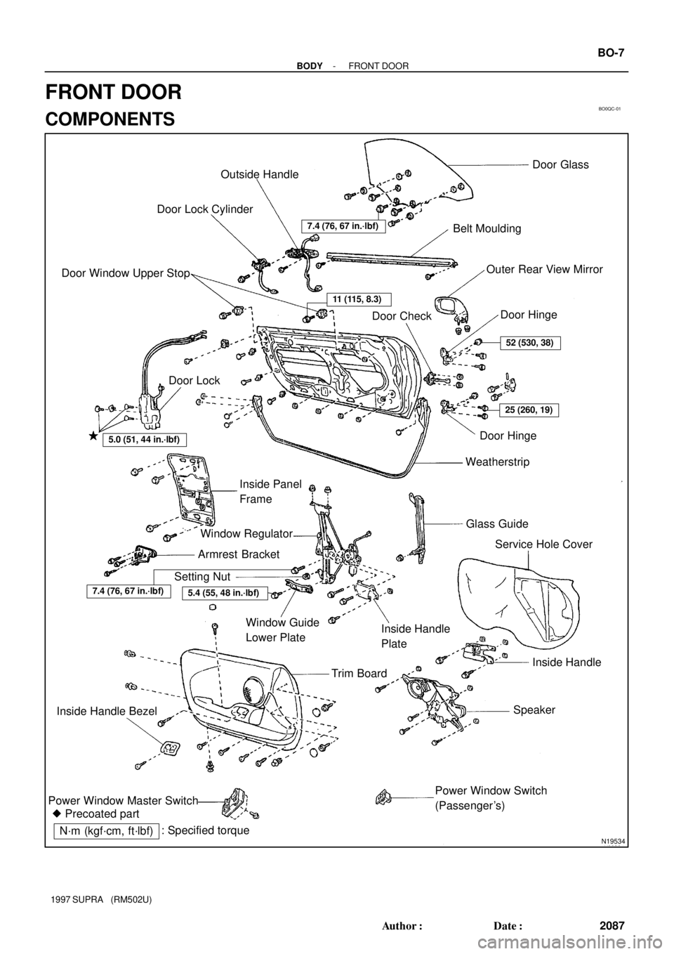
BO0QC-01
N19534
Outside Handle
Door Lock CylinderDoor Glass
Belt Moulding
Outer Rear View Mirror
Door Hinge
Door Check Door Window Upper Stop
Door Lock
Door Hinge
Weatherstrip
Glass Guide
Service Hole Cover Inside Panel
Frame
Window Regulator
Armrest Bracket
Setting Nut
Window Guide
Lower PlateInside Handle
Plate
Trim BoardInside Handle
Speaker
Power Window Switch
(Passenger's) Inside Handle Bezel
Power Window Master Switch
� Precoated part
7.4 (76, 67 in.´lbf)
11 (115, 8.3)
52 (530, 38)
25 (260, 19)
5.0 (51, 44 in.´lbf)
5.4 (55, 48 in.´lbf)7.4 (76, 67 in.´lbf)
N´m (kgf´cm, ft´lbf): Specified torque
- BODYFRONT DOOR
BO-7
2087 Author�: Date�:
1997 SUPRA (RM502U)
FRONT DOOR
COMPONENTS