Page 1486 of 1807

Connect
P12549
- SFI (2JZ-GTE)INJECTOR
SF-27
1353 Author�: Date�:
1997 SUPRA (RM502U)
(i) Connect the TOYOTA hand-held tester to the DLC3.
(j)")
Q08242
TOYOTA Hand-Held Tester
DLC3
P12548
SST (Wire)
Connect
P12549
- SFI (2JZ-GTE)INJECTOR
SF-27
1353 Author�: Date�:
1997 SUPRA (RM502U)
(i) Connect the TOYOTA hand-held tester to the DLC3.
(j) Turn the ignition switch ON and TOYOTA hand-held tes-
ter main switch ON.
NOTICE:
Do not start the engine.
(k) Select the active test mode on the TOYOTA hand-held
tester.
(l) Please refer to the TOYOTA hand-held tester operator's
manual for further details.
(m) If you have no TOYOTA hand-held tester, connect the
positive (+) and negative (-) leads from the battery to the
fuel pump connector.
(n) Connect SST (wire) to the injector and battery for 15 se-
conds, and measure the injection volume with a gra-
duated cylinder. Test each injector 2 or 3 times.
SST 09842-30060
Injection volume:
111 - 141 cm
3 (6.8 - 8.6 cu in.) per 15 sec.
Difference between each injector:
10 cm
3 (0.6 cu in.) or less
If the injection volume is not as specified, replace the injector.
2. INSPECT LEAKAGE
(a) In the condition above, disconnect the tester probes of
SST (wire) from the battery and check the fuel leakage
from the injector.
SST 09842-30060
Fuel drop:
One drop or less per minutes
(b) Turn the ignition switch to LOCK.
(c) Disconnect the negative (-) terminal cable from the bat-
tery.
(d) Remove the SST.
SST 09268-41046
(e) Reconnect the fuel inlet hose to the fuel filter with 2 new
gaskets and the union bolt.
Torque: 29 N´m (300 kgf´cm, 22 ft´lbf)
(f) Reconnect the fuel return hose to the fuel return pipe.
(g) Remove the 6 bolts, 3 injector holders and 6 insulators.
(h) Disconnect the TOYOTA hand- held tester from the
DLC3.
Page 1495 of 1807
MASS AIR FLOW (MAF) METER
1364 Author�: Date�:
1997 SUPRA (RM502U)
INSPECTION
1. INSPECT MAF METER RESISTANCE
Using a")
SF0H4-01
FI6961
E2
THa Ohmmeter
P12997
Voltmeter
VG
E21 Air SF-38
- SFI (2JZ-GTE)MASS AIR FLOW (MAF) METER
1364 Author�: Date�:
1997 SUPRA (RM502U)
INSPECTION
1. INSPECT MAF METER RESISTANCE
Using an ohmmeter, measure the resistance between terminals
THA and E2.
Resistance:
-20°C (-4°F)10 - 20 kW
0°C (32°F)4 - 7 kW
20°C (68°F)2 - 3 kW
40°C (104°F)0.9 - 1.3 kW
60°C (140°F)0.4 - 0.7 kW
If the resistance is not as specified, replace the MAF meter.
2. INSPECT MAF METER OPERATION
(a) Connectfthe MAF meter connector.
(b) Connectfthe negative (-) terminal cable to the battery.
(c) Using a voltmeter, connect the positive (+) tester probe to
terminal VG, and negative (-) tester probe to terminal
E21.
(d) Turn the ignition switch ON.
(e) Blow air into the MAF meter, and check that the voltage
fluctuates.
If operation is not as specified, replace the MAF meter.
(f) Turn the ignition switch OFF.
(g) Disconnect the negative (-) terminal cable from the bat-
tery.
(h) Disconnect the MAF meter connector.
Page 1534 of 1807
SF0I5-01
P11390
Disconnect
P11419
Voltmeter
E2VC
P11984
P12022
Disconnect
- SFI (2JZ-GTE)TURBO PRESSURE SENSOR
SF-79
1405 Author�: Date�:
1997 SUPRA (RM502U)
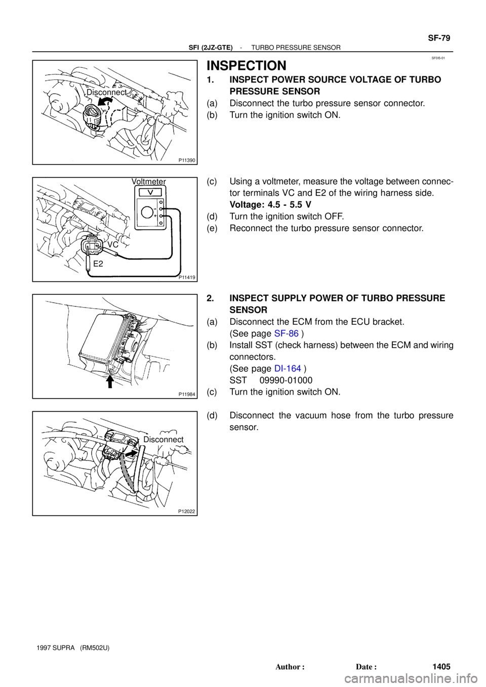
INSPECTION
1. INSPECT POWER SOURCE VOLTAGE OF TURBO
PRESSURE SENSOR
(a) Disconnect the turbo pressure sensor connector.
(b) Turn the ignition switch ON.
(c) Using a voltmeter, measure the voltage between connec-
tor terminals VC and E2 of the wiring harness side.
Voltage: 4.5 - 5.5 V
(d) Turn the ignition switch OFF.
(e) Reconnect the turbo pressure sensor connector.
2. INSPECT SUPPLY POWER OF TURBO PRESSURE
SENSOR
(a) Disconnect the ECM from the ECU bracket.
(See page SF-86)
(b) Install SST (check harness) between the ECM and wiring
connectors.
(See page DI-164)
SST 09990-01000
(c) Turn the ignition switch ON.
(d) Disconnect the vacuum hose from the turbo pressure
sensor.
Page 1542 of 1807

CH03L-01
P11586
Z18809
Except Maintenance-Free Battery
Z18810
Maintenance-Free BatteryVoltmeter
Z11580
Blue
OKWhite
Charging
NecessaryRed
Insufficient
Water Maintenance-Free Battery CH-2
- CHARGINGCHARGING SYSTEM
1525 Author�: Date�:
1997 SUPRA (RM502U)
ON-VEHICLE INSPECTION
1. CHECK BATTERY ELECTROLYTE LEVEL
Check the electrolyte quantity of each cell.
Maintenance-Free Battery:
If under the lower level, replace the battery (or add distilled wa-
ter if possible). Check the charging system.
Except Maintenance-Free Battery:
If under the lower level, add distilled water.
2. Except Maintenance-Free Battery:
CHECK BATTERY SPECIFIC GRAVITY
Check the specific gravity of each cell.
Standard specific gravity: 1.25 - 1.29 at 20°C (68°F)
If the specific gravity is less than specification, charge the bat-
tery.
3. Maintenance-Free Battery:
CHECK BATTERY POSITIVE VOLTAGE
(a) After having driven the vehicle and in the case that 20
minutes have not passed after having stopped the en-
gine, turn the ignition switch ON and turn on the electrical
system (headlight, blower motor, rear defogger etc.) for
60 seconds to remove the surface charge.
(b) Turn the ignition switch OFF and turn off the electrical sys-
tems.
(c) Measure the battery positive voltage between the nega-
tive (-) and positive (+) terminals of the battery.
Standard voltage: 12.5 - 12.9 V at 20°C (68°F)
If the voltage is less than specification, charge the battery.
HINT:
Check the indicator as shown in the illustration.
4. CHECK BATTERY TERMINALS AND FUSES
(a) Check that the battery terminals are not loose or cor-
roded.
If the terminals are corroded, clean the terminals.
(b) Check the fuses for continuity.
Page 1544 of 1807

6. REMOVE ENGINE UNDER COVER
7. VI")
Z03473
Disconnect Wire
from Terminal B Ammeter
Battery
Generator
Voltmeter
P10822Terminal F CH-4
- CHARGINGCHARGING SYSTEM
1527 Author�: Date�:
1997 SUPRA (RM502U)
6. REMOVE ENGINE UNDER COVER
7. VISUALLY CHECK GENERATOR WIRING AND
LISTEN FOR ABNORMAL NOISES
(a) Check that the wiring is in good condition.
(b) Check that there is no abnormal noise from the generator
while the engine is running.
8. CHECK CHARGE WARNING LIGHT CIRCUIT
(a) Warm up the engine and then turn it off.
(b) Turn off all accessories.
(c) Turn the ignition switch ºONº. Check that the charge warn-
ing light is lit.
(d) Start the engine. Check that the light goes off.
If the light does not go off as specified, troubleshoot the charge
light circuit.
9. INSPECT CHARGING CIRCUIT WITHOUT LOAD
HINT:
If a battery/generator tester is available, connect the tester to
the charging circuit as per manufacturer's instructions.
(a) If a tester is not available, connect a voltmeter and amme-
ter to the charging circuit as follows:
�Disconnect the wire from terminal B of the genera-
tor, and connect it to the negative (-) probe of the
ammeter.
�Connect the positive (+) probe of the ammeter to
terminal B of the generator.
�Connect the positive (+) probe of the voltmeter to
terminal B of the generator.
�Ground the negative (-) probe of the voltmeter.
(b) Check the charging circuit as follows:
With the engine running from idling to 2,000 rpm, check
the reading on the ammeter and voltmeter.
Standard amperage: 10 A or less
Standard voltage: 13.2 - 14.8 V
If the voltmeter reading is more than standard voltage, replace
the voltage regulator.
If the voltmeter reading is less than standard voltage, check the
voltage regulator and generator as follows:
�With terminal F grounded, start the engine and
check the voltmeter reading of terminal B.
�If the voltmeter reading is more than standard volt-
age, replace the voltage regulator.
�If the voltmeter reading is less than standard volt-
age, check the generator.
Page 1580 of 1807

REMOVAL
1. REMOVE STEERING WHEEL PAD
NOTICE:
If the airbag connector is disconnected with the ignition
switch")
SR13Y-01
- STEERINGTILT STEERING COLUMN
SR-1 1
1895 Author�: Date�:
1997 SUPRA (RM502U)
REMOVAL
1. REMOVE STEERING WHEEL PAD
NOTICE:
If the airbag connector is disconnected with the ignition
switch at ON or ACC, DTCs will be recorded. Never use air-
bag parts from another vehicle. When replacing parts, re-
place with new parts.
(a) Place the front wheels facing straight ahead.
(b) Using a torx socket wrench, loosen the 2 torx screws.
HINT:
Loosen the 2 screws until the groove along the screw circumfer-
ence catches on the screw case.
(c) Pull the pad out from the steering wheel and disconnect
the airbag connector.
CAUTION:
When storing the pad, keep the upper surface of the pad
facing upward. Never disassemble the pad.
NOTICE:
When removing the pad, take care not to pull the airbag
wire harness.
2. REMOVE STEERING WHEEL
(a) Disconnect the connector.
(b) Remove the wheel set nut.
(c) Place matchmarks on the wheel and main shaft.
(d) Using SST, remove the wheel.
SST 09950-50010 (09951-05010, 09952-05010,
09953-05020, 09954-05020)
3. REMOVE UPPER AND LOWER COLUMN COVERS
Remove 5 screws.
Page 1582 of 1807

DISASSEMBLY
NOTICE:
When using a vise, do not overtighten it.
1. REMOV")
SR13Z-01
R07558
Matchmarks
R07559
Screw
Extractor
- STEERINGTILT STEERING COLUMN
SR-13
1897 Author�: Date�:
1997 SUPRA (RM502U)
DISASSEMBLY
NOTICE:
When using a vise, do not overtighten it.
1. REMOVE IGNITION KEY CYLINDER ILLUMINATION
2. REMOVE INTERMEDIATE SHAFT
Remove the bolt.
3. REMOVE SLIDING YOKE AND SHAFT THRUST STOP-
PER
(a) Remove the bolt.
(b) Shift the stopper.
(c) Place matchmarks on the sliding yoke and main shaft.
4. REMOVE COLUMN LOWER COVER
Loosen the clamp.
5. REMOVE COLUMN UPPER BRACKET AND COLUMN
UPPER CLAMP
(a) Using a centering punch, mark the center of the 2 ta-
pered-head bolts.
(b) Using a 4 - 5 mm (0.16 - 0.20 in.) drill, drill into the 2 ta-
pered-head bolts.
(c) Using a screw extractor, remove the 2 tapered-head
bolts.
6. REMOVE WIRING HARNESS CLAMP AND COLUMN
PROTECTOR
Remove the 2 screws.
7. REMOVE COMPRESSION SPRING
(a) Using a torx socket wrench, remove the screw.
(b) Remove the 2 bushings from the spring.
8. REMOVE 3 TENSION SPRINGS
9. REMOVE STEERING DAMPER
Remove the 2 bolts.
10. REMOVE TURN SIGNAL BRACKET
Remove the 2 bolts.
Page 1585 of 1807

INSPECTION
1. INSPECT COLUMN UPPER BRACKET
Check that the steerin")
SR140-01
R11204
R11203
Screwdriver
Key Cylinder
R01835
SR-16
- STEERINGTILT STEERING COLUMN
1900 Author�: Date�:
1997 SUPRA (RM502U)
INSPECTION
1. INSPECT COLUMN UPPER BRACKET
Check that the steering lock mechanism operates properly.
2. IF NECESSARY, REPLACE KEY CYLINDER
(a) Place the ignition key at the ACC position.
(b) Push down the stop pin with a screwdriver and pull out the
key cylinder.
(c) Install a new key cylinder.
HINT:
Make sure the ignition key is at the ACC position.
3. INSPECT IGNITION SWITCH
(See page BE-13)
4. IF NECESSARY, REPLACE IGNITION SWITCH
(a) Remove the 2 screws.
(b) Install new switch with the 2 screws.
5. INSPECT KEY UNLOCK WARNING SWITCH
(See page BE-13)
6. A/T:
INSPECT KEY INTERLOCK SOLENOID
(See page AT-17, AT-15)
7. IF NECESSARY, REPLACE KEY UNLOCK WARNING
SWITCH
(a) Remove the 2 screws.
(b) Install a new switch with the 2 screws.
8. A/T:
IF NECESSARY, REPLACE KEY INTERLOCK SOLE-
NOID WITH KEY UNLOCK WARNING SWITCH
(a) Remove the 4 screws.
(b) Install a new solenoid and warning switch with the 4
screws.
9. IF NECESSARY, REPLACE BUSHING
(a) Using a screwdriver, depress the 3 projections on the bus-
ing and remove the bushing from the column lower tube.
(b) Align the projections on a new bushing with the holes in
the lower tube. Install the bushing until the projections are
firmly engaged in the holes in the lower tube.