Page 1353 of 1807
IGNITION TIMING
EM-1 1
111 6 Author�: Date�:
1997 SUPRA (RM502U)
IGNITION TIMING")
EM0AA-02
Q08242
TOYOTA Hand-Held Tester
DLC3
P11288
DLC1
TE1
E1
P11943
Green Lead
Wire
- ENGINE MECHANICAL (2JZ-GTE)IGNITION TIMING
EM-1 1
111 6 Author�: Date�:
1997 SUPRA (RM502U)
IGNITION TIMING
INSPECTION
1. WARM UP ENGINE
Allow the engine to warm up to normal operating temperature.
2. CONNECT TOYOTA HAND-HELD TESTER OR OBDII
SCAN TOOL
(a) Connect the TOYOTA hand-held tester or OBDII scan
tool to the DLC3.
(b) Please refer to the TOYOTA hand-held tester or OBDII
scan tool operator's manual for further details.
3. CONNECT TIMING LIGHT TO ENGINE
4. CHECK IDLE SPEED
(a) Race the engine speed at 2,500 rpm for approx. 90 se-
conds.
(b) Check the idle speed.
Idle speed: 650 ± 50 rpm
5. INSPECT IGNITION TIMING
(a) Using SST, connect terminals TE1 and E1 of the DLC1.
SST 09843-18020
(b) Open the igniter connector cover and remove the green
lead wire.
(c) Connect the timing light clip to the green lead wire.
NOTICE:
�Use a timing light that can detect the primary signal.
�After finishing the inspection, make sure the lead wire
is stored inside the connector cover.
(d) Using a timing light, check the ignition timing.
Ignition timing: 10 ± 2° BTDC @ idle
(Transmission in neutral position)
Page 1354 of 1807
EM-12
- ENGINE MECHANICAL (2JZ-GTE)IGNITION TIMING
111 7 Author�: Date�:
1997 SUPRA (RM502U)
(e) Remove the SST from the DLC1.
SST 09843-18020
6. FURTHER CHECK IGNITION TIMING
Ignition timing: 10 - 20° BTDC @ idle
(Transmission in neutral position)
HINT:
The timing mark moves in a range between 10° and 20°.
7. DISCONNECT TIMING LIGHT FROM ENGINE
8. DISCONNECT TOYOTA HAND- HELD TESTER OR
OBDII SCAN TOOL
Page 1376 of 1807

REMOVAL
HINT:
When repairing the oil pump, the oil pan and strainer should be
removed and cleaned.
1. REMOVE ENGIN")
LU0K0-01
P11911
- LUBRICATIONOIL PUMP
LU-9
1456 Author�: Date�:
1997 SUPRA (RM502U)
REMOVAL
HINT:
When repairing the oil pump, the oil pan and strainer should be
removed and cleaned.
1. REMOVE ENGINE WITH TRANSMISSION
(2JZ-GE: See page EM-57)
(2JZ-GTE: See page EM-58)
2. SEPARATE ENGINE AND TRANSMISSION
(2JZ-GE: See page AT-20)
(2JZ-GTE: See page EM-58)
3. INSTALL ENGINE TO ENGINE STAND FOR REMOVAL
4. REMOVE GENERATOR (See page CH-8)
5. REMOVE CRANKSHAFT POSITION SENSOR
(a) Disconnect the sensor connector from the clamp bracket.
(b) Disconnect the sensor connector from the wiring connec-
tor.
(c) 2JZ-GTE:
Disconnect the wire clamp from the cylinder block.
(d) Remove the bolt and position sensor.
6. REMOVE TIMING BELT
(2JZ-GE: See page EM-13)
(2JZ-GTE: See page EM-15)
7. 2JZ-GTE M/T:
REMOVE DRIVE BELT TENSIONER BRACKET
Remove the 2 nuts and tensioner bracket.
8. REMOVE IDLER PULLEY AND CRANKSHAFT TIMING
PULLEY
(2JZ-GE: See page EM-13)
(2JZ-GTE: See page EM-15)
9. REMOVE OIL DIPSTICK AND GUIDE
(a) Remove the bolt.
(b) Pull out the dipstick guide together with the dipstick.
(c) Remove the O-ring from the dipstick guide.
10. REMOVE OIL LEVEL SENSOR
(a) Disconnect the level sensor connector.
(b) Remove the 4 bolts and level sensor.
(c) Remove the gasket from the level sensor.
NOTICE:
Be careful not to drop the oil level sensor when removing
it.
Page 1384 of 1807

(b) Apply seal packing to the No.2 oil pan as shown in the il-
lustration.
Seal")
Z17257
Seal WidthAB
4 - 5 mmA
B
P02404
New Gasket LU-18
- LUBRICATIONOIL PUMP
1465 Author�: Date�:
1997 SUPRA (RM502U)
(b) Apply seal packing to the No.2 oil pan as shown in the il-
lustration.
Seal packing:
Part No. 08826-00080 or equivalent
�Install a nozzle that has been cut to a 4 - 5 mm (0.16
- 0.20 in.) opening.
HINT:
Avoid applying an excessive amount to the surface.
�Parts must be assembled within 5 minutes of ap-
plication. Otherwise the material must be removed
and reapplied.
�Immediately remove nozzle from the tube and rein-
stall cap.
(c) Install the No.2 oil pan with the 14 bolts and 2 nuts.
Torque: 8.8 N´m (90 kgf´cm, 78 in.´lbf)
7. INSTALL OIL LEVEL SENSOR
(a) Install a new gasket to the level sensor.
(b) Install the level sensor with the 4 bolts.
Torque: 5.4 N´m (55 kgf´cm, 48 in.´lbf)
(c) Connect the level sensor connector.
8. INSTALL OIL DIPSTICK GUIDE AND DIPSTICK
(a) Install a new O-ring on the dipstick guide.
(b) Apply new oil to the O-ring.
(c) Connect the dipstick guide end to the dipstick tube of the
oil pan.
(d) Install the dipstick guide with the bolt.
(e) Install the dipstick.
9. INSTALL CRANKSHAFT TIMING PULLEY AND IDLER
PULLEY
(2JZ-GE: See page EM-19)
(2JZ-GTE: See page EM-21)
10. 2JZ-GTE M/T:
INSTALL DRIVE BELT TENSIONER BRACKET
Torque: 27 N´m (280 kgf´cm, 20 ft´lbf)
11. INSTALL TIMING BELT
(2JZ-GE: See page EM-19)
(2JZ-GTE: See page EM-21)
12. INSTALL CRANKSHAFT POSITION SENSOR
Torque: 9.0 N´m (90 kgf´cm, 80 in.´lbf)
13. INSTALL GENERATOR (See page CH-18)
14. REMOVE ENGINE STAND FROM ENGINE
15. ASSEMBLY ENGINE AND TRANSMISSION
(2LZ-GE: See page AT-24)
(2JZ-GTE: See page EM-65)
16. INSTALL ENGINE WITH TRANSMISSION
(2JZ-GE: See page EM-57)
(2JZ-GTE: See page EM-65)
Page 1404 of 1807
PP0QD-01
PP-8
- PREPARATIONENGINE MECHANICAL (2JZ-GTE)
54 Author�: Date�:
1997 SUPRA (RM502U)
ENGINE MECHANICAL (2JZ-GTE)
SST (Special Service Tools)
09201-10000Valve Guide Bushing Remover &
Replacer Set
(09201-01060)Valve Guide Bushing Remover &
Replacer 6
09202-70020Valve Spring Compressor
(09202-00010)Attachment
09213-70010Crankshaft Pulley Holding Tool
09222-30010Connecting Rod Bushing Remover
& Replacer
09223-15030Oil Seal & Bearing ReplacerCrankshaft rear oil seal
09248-55040Valve Clearance Adjust Tool Set
(09248-05410)Valve Lifter Press
(09248-05420)Valve Lifter Stopper
09316-6001 1Transmission & Transfer Bearing
Replacer
(09316-0001 1)Replacer PipeCrankshaft front oil seal
Camshaft oil seal
Page 1420 of 1807

UNDER HOOD
GENERAL MAINTENANCE
1. GENERAL NOTES
�Maintenance items may vary from country to country. Check the owners m")
MA01F-02
MA-4
- MAINTENANCEUNDER HOOD
41 Author�: Date�:
1997 SUPRA (RM502U)
UNDER HOOD
GENERAL MAINTENANCE
1. GENERAL NOTES
�Maintenance items may vary from country to country. Check the owner's manual supplement in which
the maintenance schedule is shown.
�Every service item in the periodic maintenance schedule must be performed.
�Periodic maintenance service must be performed according to whichever interval in the periodic main-
tenance schedule occurs first, the odometer reading (miles) or the time interval (months).
�Maintenance service after the last period should be performed at the same interval as before unless
otherwise noted.
�Failure to do even one item an cause the engine to run poorly and increase exhaust emissions.
2. WINDSHIELD WASHER FLUID
Check that there is sufficient fluid in the tank.
3. ENGINE COOLANT LEVEL
Check that the coolant level is between the ºFULLº and ºLOWº lines on the see-through reservoir.
4. RADIATOR AND HOSES
(a) Check that the front of the radiator is clean and not blocked with leaves, dirt or bugs.
(b) Check the hoses for cracks, kinks, rot or loose connections.
5. BATTERY ELECTROLYTE LEVEL
Check that the electrolyte level of all battery cells is between the upper and lower level lines on the case.
6. BRAKE AND CLUTCH FLUID LEVELS
Check that the brake and clutch fluid levels are near the upper level line on the see-through reservoirs.
7. ENGINE DRIVE BELT
Check drive belt for fraying, cracks, wear or oil contamination.
8. ENGINE OIL LEVEL
Check the level on the dipstick with the engine turned off.
9. POWER STEERING FLUID LEVEL
�Check the level on the dipstick.
�The level should be in the ºHOTº or ºCOLDº range depending on the fluid temperature.
10. AUTOMATIC TRANSMISSION FLUID LEVEL
(a) Park the vehicle on a level surface.
(b) With the engine idling and the parking brake applied, shift the selector into all positions from ºPº to ºLº,
and then shift into ºPº position.
(c) Pull out the dipstick and wipe off the fluid with a clean rag. Re-insert the dipstick and check that the
fluid level is in the HOT range.
(d) Do this check with the fluid at normal driving temperature (70 - 80°C, 158 - 176°F).
HINT:
Wait until the engine cools down (approx. 30 min.) before checking the fluid level after extended driving at
high speeds, in hot weather, in heavy traffic or pulling a trailer.
11. EXHAUST SYSTEM
If any change in the sound of the exhaust or smell of the exhaust fumes is noticed, have the cause located
and corrected.
Page 1422 of 1807

13. ACCELERATOR PEDAL
Check the pedal for smooth operation and uneven pedal effort or catching.
14. CLUTCH PEDAL (See page CL-")
- MAINTENANCEINSIDE VEHICLE
MA-3
40 Author�: Date�:
1997 SUPRA (RM502U)
13. ACCELERATOR PEDAL
Check the pedal for smooth operation and uneven pedal effort or catching.
14. CLUTCH PEDAL (See page CL-3)
(a) Check the pedal for smooth operation.
(b) Check that the pedal has the proper freeplay.
15. BRAKE PEDAL (See page BR-7 )
(a) Check the pedal for smooth operation.
(b) Check that the pedal has the proper reserve distance and freeplay.
(c) Check the brake booster function.
16. BRAKES
At a safe place, check that the brakes do not pull to one side when applied.
17. PARKING BRAKE (See page BR-9)
(a) Check that the lever has the proper travel.
(b) On a safe incline, check that the vehicle is held securely with only the parking brake applied.
18. AUTOMATIC TRANSMISSION ºPARKº MECHANISM
(a) Check the lock release button of the selector lever for proper and smooth operation.
(b) On a safe incline, check that the vehicle is held securely with the selector lever in ºPº position and all
brakes released.
Page 1424 of 1807
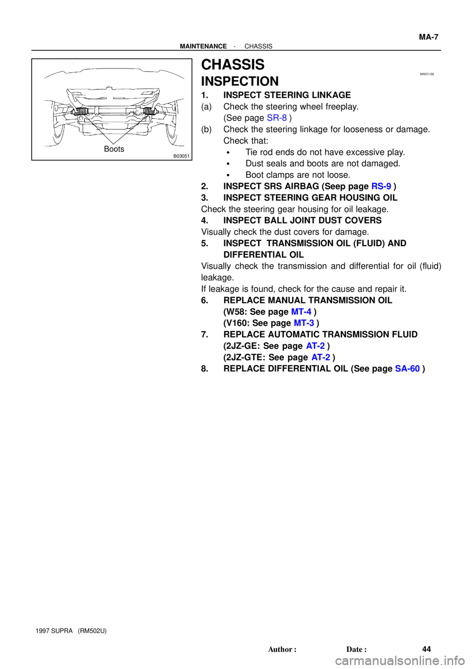
B03051Boots
MA01I-02
- MAINTENANCECHASSIS
MA-7
44 Author�: Date�:
1997 SUPRA (RM502U)
CHASSIS
INSPECTION
1. INSPECT STEERING LINKAGE
(a) Check the steering wheel freeplay.
(See page SR-8)
(b) Check the steering linkage for looseness or damage.
Check that:
�Tie rod ends do not have excessive play.
�Dust seals and boots are not damaged.
�Boot clamps are not loose.
2. INSPECT SRS AIRBAG (Seep page RS-9)
3. INSPECT STEERING GEAR HOUSING OIL
Check the steering gear housing for oil leakage.
4. INSPECT BALL JOINT DUST COVERS
Visually check the dust covers for damage.
5. INSPECT TRANSMISSION OIL (FLUID) AND
DIFFERENTIAL OIL
Visually check the transmission and differential for oil (fluid)
leakage.
If leakage is found, check for the cause and repair it.
6. REPLACE MANUAL TRANSMISSION OIL
(W58: See page MT-4)
(V160: See page MT-3)
7. REPLACE AUTOMATIC TRANSMISSION FLUID
(2JZ-GE: See page AT-2)
(2JZ-GTE: See page AT-2)
8. REPLACE DIFFERENTIAL OIL (See page SA-60)