Page 1477 of 1807
INJECTOR
1344 Author�: Date�:
1997 SUPRA (RM502U)
INJECTOR
ON-VEHICLE INSPECTION
1. INSPECT INJECTOR OPERATION
Check operation")
P11358Sound Scope
SF0GQ-01
P11359
P11416
Ohmmeter SF-18
- SFI (2JZ-GTE)INJECTOR
1344 Author�: Date�:
1997 SUPRA (RM502U)
INJECTOR
ON-VEHICLE INSPECTION
1. INSPECT INJECTOR OPERATION
Check operation sound from each injector.
(1) With the engine running or cranking, use a sound
scope to check that there is normal operating noise
in proportion to engine speed.
(2) If you have no sound scope, you can check the in-
jector transmission operation with your finger.
If no sound is heard or unusual vibration is felt, check the wiring
connector, injector or injection signal from the ECM.
2. INSPECT INJECTOR RESISTANCE
(a) Disconnect the throttle body without disconnecting the
water bypass hoses from the air intake chamber.
(See page SF-42)
(b) Disconnect the 6 injector connectors.
(c) Using an ohmmeter, measure the resistance between the
injector terminals.
Resistance: Approx. 1.95 W at 20°C (68°F)
If the resistance is not as specified, replace the injector.
(d) Reconnect the 6 injector connectors.
(e) Reinstall the throttle body to the air intake chamber.
(See page SF-48)
Page 1479 of 1807
 (2) (3)(4) SF-20
- SFI (2JZ-GTE)INJECTOR
1346 Author�: Date�:
1997 SUPRA")
SF0GS-02
P12565
Pull
O-Ring
S00910
Engine Wire Clamp
O-Ring
Pull
Fuel
Return
Hose
P11322
Chamber
StagCable
Bracket
P11321(1) (2) (3)(4) SF-20
- SFI (2JZ-GTE)INJECTOR
1346 Author�: Date�:
1997 SUPRA (RM502U)
REMOVAL
1. REMOVE ENGINE UNDER COVER
2. REMOVE THROTTLE BODY
(See page SF-43)
3. REMOVE OIL DIPSTICK AND GUIDE FOR A/T
(a) Remove the bolt.
(b) Pull out the dipstick guide together with the dipstick.
HINT:
At the time of installation, please refer to the following items.
Apply clean transmission oil to the O-ring, and push in the dip-
stick guide.
(c) Remove the O-ring from the dipstick guide.
HINT:
At the time of installation, please refer to the following items.
Use a new O-ring.
4. REMOVE OIL DIPSTICK AND GUIDE FOR ENGINE
(a) Disconnect the fuel return hose from the clamp of the dip-
stick guide.
(b) Remove the bolt.
(c) Pull out the dipstick guide together with the dipstick.
HINT:
At the time of installation, please refer to the following items.
Apply clean engine oil to the O-ring, and push in the dipstick
guide.
(d) Remove the O-ring from the dipstick guide.
HINT:
At the time of installation, please refer to the following items.
Use a new O-ring.
5. REMOVE AIR INTAKE CHAMBER STAY
Remove the bolt, nut and chamber stay.
Torque: 19 N´m (195 kgf´cm, 14 ft´lbf)
6. DISCONNECT CONTROL CABLE BRACKET FROM
AIR INTAKE CHAMBER
Remove the 2 bolts, and disconnect the cable bracket from the
air intake chamber.
Torque: 19 N´m (195 kgf´cm, 14 ft´lbf)
7. DISCONNECT CONNECTORS AND HOSES
(a) Disconnect these connectors:
(1) IAC valve connector
(2) Turbo pressure sensor connector
(3) VSV connector for fuel pressure control
(4) VSV connector for EGR
Page 1496 of 1807
THROTTLE BODY
1366 Author�: Date�:
1997 SUPRA (RM502U)
THROTTLE BODY
ON-VEHICLE INSPECTION
1. INSPECT THROTT")
P11325
SF0H6-01
P12079
P12560
Turn
Dashpot
Adjusting Screw
Push Rod SF-40
- SFI (2JZ-GTE)THROTTLE BODY
1366 Author�: Date�:
1997 SUPRA (RM502U)
THROTTLE BODY
ON-VEHICLE INSPECTION
1. INSPECT THROTTLE BODY
(a) Check that the throttle linkage moves smoothly.
(b) Check the vacuum at the purge port.
�Start the engine.
�Check the vacuum with your finger.
Port nameAt idleAt 3,000 rpm
PurgeNo vacuumVacuum
2. INSPECT DASHPOT
(a) Warm up engine.
Allow the engine to warm up to normal operating tempera-
ture.
(b) Check idle speed.
Idle speed (Transmission in neutral position):
650 ± 50 rpm
(c) Check and adjust dashpot setting speed.
(1) Disconnect the control cables from the throttle
body.
(2) Turn the throttle linkage until the dashpot adjusting
screw starts to separate from the push rod. Then
keep the throttle linkage at that position.
(3) Check that the dashpot is set.
Dashpot setting speed: 2,300 ± 400 rpm
(4) Reconnect the control cables to the throttle body.
(d) Check VTV operation
(1) Maintain the engine speed at 3,500 rpm.
(2) Release the throttle valve, and check that the en-
gine returns to idle in a few seconds.
Page 1497 of 1807
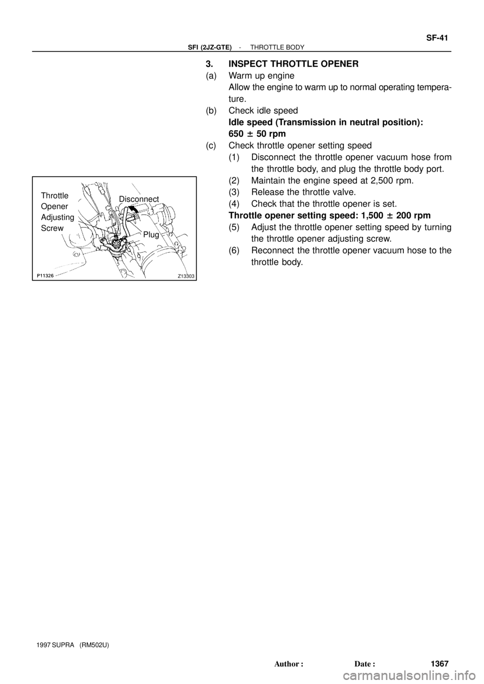
Z13303
Disconnect
PlugThrottle
Opener
Adjusting
Screw
- SFI (2JZ-GTE)THROTTLE BODY
SF-41
1367 Author�: Date�:
1997 SUPRA (RM502U)
3. INSPECT THROTTLE OPENER
(a) Warm up engine
Allow the engine to warm up to normal operating tempera-
ture.
(b) Check idle speed
Idle speed (Transmission in neutral position):
650 ± 50 rpm
(c) Check throttle opener setting speed
(1) Disconnect the throttle opener vacuum hose from
the throttle body, and plug the throttle body port.
(2) Maintain the engine speed at 2,500 rpm.
(3) Release the throttle valve.
(4) Check that the throttle opener is set.
Throttle opener setting speed: 1,500 ± 200 rpm
(5) Adjust the throttle opener setting speed by turning
the throttle opener adjusting screw.
(6) Reconnect the throttle opener vacuum hose to the
throttle body.
Page 1624 of 1807

62
- STEERINGPROGRESSIVE POWER STEERING (PPS)
SR-55
1939 Author�: Date�:
1997 SUPRA (RM502U)
(e) Inspect the PPS solenoid valve circuit.
(")
F03098
Wire Harness Side:
R07587
62
R07587
37 mph (60 km/h)
62
- STEERINGPROGRESSIVE POWER STEERING (PPS)
SR-55
1939 Author�: Date�:
1997 SUPRA (RM502U)
(e) Inspect the PPS solenoid valve circuit.
(1) Disconnect the PPS ECU connector.
(2) Check continuity between the terminals of the con-
nector on wire harness side, as shown in the illustra-
tion.
Tester connectionSpecified condition
1 - 6No continuity
2 - 6No continuity
If it is not as specified, repair or replace wire harness or connec-
tor.
(3) Connect the PPS ECU connector.
4. INSPECT PPS ECU
(a) Jack up the vehicle and support it on stands.
(b) Start the engine.
(c) Measure the voltage of ECU.
(1) Using a voltmeter, measure the voltage between
ECU terminals 2 and 6 while the engine is idling.
Standard voltage: 0.15 - 0.20 V
(2) Place the transmission in gear and while running at
about 62 mph (100 km/h), measure the voltage be-
tween ECU terminals 2 and 6.
Standard voltage:
2JZ-GE: 0.06 - 0.17 v
2JZ-GTE: 0.07 - 0.17 v
If no voltage, try another ECU for SUPRA.
(d) Lower the vehicle.
Page 1731 of 1807

165 Author�: Date�:
1997 SUPRA (RM502U) Fuel pipe support x Cylinder block
2829021
Oil filter bracket x Cylinder block8890065
No.2 water bypa")
SS-8
- SERVICE SPECIFICATIONSENGINE MECHANICAL (2JZ-GE)
165 Author�: Date�:
1997 SUPRA (RM502U) Fuel pipe support x Cylinder block
2829021
Oil filter bracket x Cylinder block8890065
No.2 water bypass pipe x Water pump, Cylinder block2121015
Flywheel (M/T) x x Crankshaft 1st
2nd49
Turn 90°500
Turn 90°36
Turn 90°
Drive plate (A/T) x Crankshaft8385061
Clutch cover x Flywheel M/T1919514
Cylinder block x Transmission 14 mm head
17 mm head39
72400
73029
43
Drive plate x Torque converter clutch A/T3334025
Oil cooler tube x Union for transmission A/T3435025
Rear support member x Body2526019
Rear support member x Engine rear mounting insulator1313510
Front suspension crossmember x Engine mounting insulator5960043
Transmission shift lever x Shift lever retainer M/T1919514
Transmission control rod x Shift lever A/T131309
No.2 front exhaust pipe x Exhaust manifold6263046
Pipe support bracket x Transmission4344032
No.2 front exhaust pipe x Front exhaust pipe5859043
Clutch release cylinder x Transmission M/T131309
Ground strap (M/T) x Transmission3738027
A/C compressor x Cylinder block Stud bolt
Bolt and nut26
52265
53019
38
PS pump bracket x A/C compressor5859043
PS pump bracket x Cylinder block3940029
Fuel inlet hose x Fuel pipe support2930022
Front exhaust pipe x Center exhaust pipe5859043
Center exhaust pipe x Tailpipe1919514
Heated oxygen sensor x Front exhaust pipe2020014
Page 1736 of 1807

SS-13
170 Author�: Date�:
1997 SUPRA (RM502U) No.2 water bypass pipe x Water pump, Cylinder block
2121015
Flywheel (M/T) x x Crankshaft 1st
2nd49")
- SERVICE SPECIFICATIONSENGINE MECHANICAL (2JZ-GTE)
SS-13
170 Author�: Date�:
1997 SUPRA (RM502U) No.2 water bypass pipe x Water pump, Cylinder block
2121015
Flywheel (M/T) x x Crankshaft 1st
2nd49
Turn 90°500
Turn 90°36
Turn 90°
Drive plate (A/T) x Crankshaft8385061
Clutch cover x Flywheel M/T1919514
Cylinder block x Transmission 14 mm head
17 mm head39
72400
73029
43
Clutch service hole cover x Clutch housing 2JZ-GTE M/T121209
Drive plate x Torque converter clutch A/T3334025
Oil cooler tube x Union for transmission A/T3435025
Rear support member x Body2526019
Rear support member x Engine rear mounting insulator1313510
Front suspension crossmember x Engine mounting insulator5960043
Transmission shift lever x Shift lever retainer M/T1919514
Transmission control rod x Shift lever A/T131309
No.2 front exhaust pipe x Exhaust manifold6263046
Pipe support bracket x Transmission4344032
No.2 front exhaust pipe x Front exhaust pipe5859043
Clutch release cylinder x Transmission M/T131309
Clutch line tube (M/T) x No.1 oil pan3738027
Ground strap (M/T) x Transmission3738027
A/C compressor x Cylinder block Stud bolt
Bolt and nut26
52265
53019
38
PS pump bracket x A/C compressor5859043
PS pump bracket x Cylinder block3940029
Fuel inlet hose x Fuel pipe support2930022
Rear center floor crossmember brace x Body2829021
Front exhaust pipe x Center exhaust pipe5859043
Center exhaust pipe x Tailpipe1919514
Heated oxygen sensor x Front exhaust pipe2020014
Page 1738 of 1807

SS-15
172 Author�: Date�:
1997 SUPRA (RM502U)
TORQUE SPECIFICATION
Part tightenedN´mkgf´cmft´lbf
Front lower arm bracket stay x Front susp")
SS0DP-02
- SERVICE SPECIFICATIONSTURBOCHARGING (2JZ-GTE)
SS-15
172 Author�: Date�:
1997 SUPRA (RM502U)
TORQUE SPECIFICATION
Part tightenedN´mkgf´cmft´lbf
Front lower arm bracket stay x Front suspension Bolt
Nut44
59450
60033
43
Upper front crossmember extension x Front suspension Bolt
Nut29
33300
34022
25
Front exhaust pipe x No.2 front exhaust pipe5859043
Pipe support bracket x Transmission4344032
No.2 front exhaust pipe x Exhaust gas control valve6263046
No.1 air tube x No.1 turbocharger2121015
No.4 air tube x No.1 turbocharger2121015
Intake air control valve x No.2 turbocharger2121015
Exhaust bypass pipe x Exhaust gas control valve2525018
Exhaust bypass pipe x Turbine outlet elbow2525018
Exhaust gas control valve stay x Cylinder block4344032
Exhaust gas control valve stay x Exhaust gas control valve4344032
Main heated oxygen sensor x Exhaust gas control valve2020014
Exhaust gas control valve x Turbine outlet elbow6970051
Turbocharger stay x Cylinder block4344032
Turbocharger stay x Turbocharger4344032
Turbo oil pipe x Cylinder block3940029
Turbo oil pipe x Turbocharger2121015
Turbocharger x Exhaust manifold5455040
No.2 air tube x No.2 turbocharger2121015
Side bearing housing plate x Turbocharger8.89078 in.´lbf
Turbo water pipe x Turbocharger8.89078 in.´lbf
Turbocharger x Turbine outlet elbow2525018
CAC duct x CAC4.95043 in.´lbf
CAC x Body1313510