Page 1344 of 1807
CYLINDER BLOCK
1197 Author�: Date�:
1997 SUPRA (RM502U)
(d) Retighten")
P02420
90°Painted Mark
90°
P02197
Seal Width
2 - 3 mm
Seal
Packing
P02104
Z16761
Adhesive EM-92
- ENGINE MECHANICAL (2JZ-GTE)CYLINDER BLOCK
1197 Author�: Date�:
1997 SUPRA (RM502U)
(d) Retighten the connecting rod cap bolts 90° in the numeri-
cal order shown.
(e) Check that the painted mark is now at a 90° angle to the
front.
(f) Check that the crankshaft turns smoothly.
14. CHECK CONNECTING ROD THRUST CLEARANCE
(See page EM-79)
15. INSTALL REAR OIL SEAL RETAINER
(a) Remove any old packing (FIPG) material and be careful
not to drop any oil on the contact surfaces of the retainer
and cylinder block.
�Using a razor blade and gasket scraper, remove all
the old packing (FIPG) material from the gasket sur-
faces and sealing groove.
�Thoroughly clean all components to remove all de-
bris.
�Using a non-residue solvent, clean both sealing
surfaces.
(b) Apply seal packing to the retainer as shown in the illustra-
tion.
Seal packing:
Part No. 08826-00080 or equivalent
�Install a nozzle that has been cut to a 2 - 3 mm (0.08
- 0.12 in.) opening.
�Parts must be assembled within 3 minutes of ap-
plication. Otherwise the material must be removed
and reapplied.
�Immediately remove nozzle from the tube and rein-
stall cap.
(c) Install the retainer with the 6 bolts.
Torque: 6.0 N´m (60 kgf´cm, 53 in.´lbf)
16. INSTALL OIL PUMP (See page LU-16)
17. INSTALL WATER PUMP (See page CO-1 1)
18. INSTALL CRANKSHAFT POSITION SENSOR
Torque: 9.0 N´m (90 kgf´cm, 80 in.´lbf)
19. INSTALL RH ENGINE MOUNTING BRACKET AND
INSULATOR ASSEMBLY
Torque: 59 N´m (590 kgf´cm, 44 ft´lbf)
20. INSTALL ENGINE COOLANT DRAIN PLUG
Torque: 30 N´m (300 kgf´cm, 22 ft´lbf)
21. INSTALL UNION FOR OIL COOLER HOSE
(a) Apply adhesive to 2 or 3 threads of the union.
Adhesive:
Part No. 08833-00070, THREE BOND 1324,
or equivalent
(b) Install the union.
Torque: 40 N´m (400 kgf´cm, 30 ft´lbf)
Page 1386 of 1807
LU04R-01
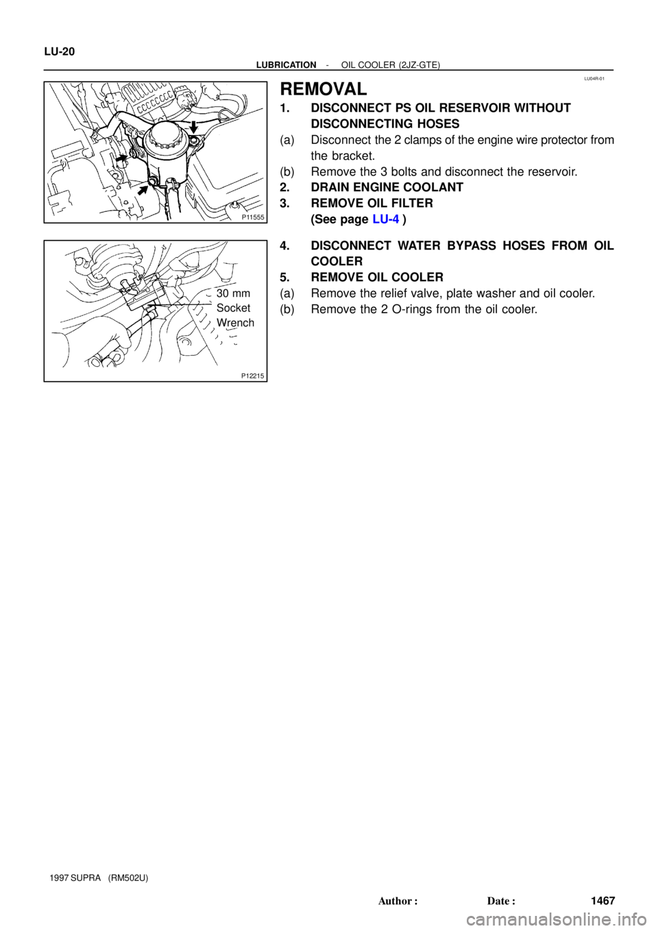
P11555
P12215
30 mm
Socket
Wrench LU-20
- LUBRICATIONOIL COOLER (2JZ-GTE)
1467 Author�: Date�:
1997 SUPRA (RM502U)
REMOVAL
1. DISCONNECT PS OIL RESERVOIR WITHOUT
DISCONNECTING HOSES
(a) Disconnect the 2 clamps of the engine wire protector from
the bracket.
(b) Remove the 3 bolts and disconnect the reservoir.
2. DRAIN ENGINE COOLANT
3. REMOVE OIL FILTER
(See page LU-4)
4. DISCONNECT WATER BYPASS HOSES FROM OIL
COOLER
5. REMOVE OIL COOLER
(a) Remove the relief valve, plate washer and oil cooler.
(b) Remove the 2 O-rings from the oil cooler.
Page 1388 of 1807
LU04T-02
P11208
New O-Ring LU-22
- LUBRICATIONOIL COOLER (2JZ-GTE)
1469 Author�: Date�:
1997 SUPRA (RM502U)
INSTALLATION
1. INSTALL OIL COOLER
(a) Install 2 new O-rings to the oil cooler.
(b) Apply a light coat of engine oil on the threads and under
the head of the relief valve.
(c) Temporarily install the oil cooler with the plate washer and
relief valve.
(d) Tighten the relief valve.
Torque: 78 N´m (800 kgf´cm, 58 ft´lbf)
2. CONNECT WATER BYPASS HOSES TO OIL
COOLER
3. CONNECT PS OIL RESERVOIR
4. INSTALL OIL FILTER
5. FILL WITH ENGINE COOLANT
6. START ENGINE AND CHECK FOR LEAKS
7. CHECK ENGINE OIL LEVEL
Page 1420 of 1807

UNDER HOOD
GENERAL MAINTENANCE
1. GENERAL NOTES
�Maintenance items may vary from country to country. Check the owners m")
MA01F-02
MA-4
- MAINTENANCEUNDER HOOD
41 Author�: Date�:
1997 SUPRA (RM502U)
UNDER HOOD
GENERAL MAINTENANCE
1. GENERAL NOTES
�Maintenance items may vary from country to country. Check the owner's manual supplement in which
the maintenance schedule is shown.
�Every service item in the periodic maintenance schedule must be performed.
�Periodic maintenance service must be performed according to whichever interval in the periodic main-
tenance schedule occurs first, the odometer reading (miles) or the time interval (months).
�Maintenance service after the last period should be performed at the same interval as before unless
otherwise noted.
�Failure to do even one item an cause the engine to run poorly and increase exhaust emissions.
2. WINDSHIELD WASHER FLUID
Check that there is sufficient fluid in the tank.
3. ENGINE COOLANT LEVEL
Check that the coolant level is between the ºFULLº and ºLOWº lines on the see-through reservoir.
4. RADIATOR AND HOSES
(a) Check that the front of the radiator is clean and not blocked with leaves, dirt or bugs.
(b) Check the hoses for cracks, kinks, rot or loose connections.
5. BATTERY ELECTROLYTE LEVEL
Check that the electrolyte level of all battery cells is between the upper and lower level lines on the case.
6. BRAKE AND CLUTCH FLUID LEVELS
Check that the brake and clutch fluid levels are near the upper level line on the see-through reservoirs.
7. ENGINE DRIVE BELT
Check drive belt for fraying, cracks, wear or oil contamination.
8. ENGINE OIL LEVEL
Check the level on the dipstick with the engine turned off.
9. POWER STEERING FLUID LEVEL
�Check the level on the dipstick.
�The level should be in the ºHOTº or ºCOLDº range depending on the fluid temperature.
10. AUTOMATIC TRANSMISSION FLUID LEVEL
(a) Park the vehicle on a level surface.
(b) With the engine idling and the parking brake applied, shift the selector into all positions from ºPº to ºLº,
and then shift into ºPº position.
(c) Pull out the dipstick and wipe off the fluid with a clean rag. Re-insert the dipstick and check that the
fluid level is in the HOT range.
(d) Do this check with the fluid at normal driving temperature (70 - 80°C, 158 - 176°F).
HINT:
Wait until the engine cools down (approx. 30 min.) before checking the fluid level after extended driving at
high speeds, in hot weather, in heavy traffic or pulling a trailer.
11. EXHAUST SYSTEM
If any change in the sound of the exhaust or smell of the exhaust fumes is noticed, have the cause located
and corrected.
Page 1427 of 1807

ENGINE
INSPECTION
1. REPLACE TIMING BELT
(2JZ-GE: See page EM-17)
(2JZ-GTE: See page EM-19)
2. INSPECT DRIVE BELT
(S")
MA0688
MA01G-01
- MAINTENANCEENGINE
MA-5
42 Author�: Date�:
1997 SUPRA (RM502U)
ENGINE
INSPECTION
1. REPLACE TIMING BELT
(2JZ-GE: See page EM-17)
(2JZ-GTE: See page EM-19)
2. INSPECT DRIVE BELT
(See page CH-2)
3. REPLACE SPARK PLUGS
(2JZ-GE: See page IG-1)
(2JZ-GTE: See page IG-1)
4. INSPECT AIR FILTER
(a) Remove the air filter.
(b) Visually check that the air filter is not excessively dam-
aged or oily.
If necessary, replace the air filter.
(c) Clean the filter with compressed air.
First blow from the inside thoroughly, then blow off the
outside of the filter.
(d) Reinstall the air filter and air cleaner case.
5. REPLACE AIR FILTER
Replace the air filter with a new one.
6. REPLACE ENGINE OIL AND OIL FILTER
(See page LU-4)
7. REPLACE ENGINE COOLANT
(See page CO-2)
8. INSPECT CHARCOAL CANISTER
(2JZ-GE: See page EC-5)
(2JZ-GTE: See page EC-5)
9. REPLACE GASKET IN FUEL TANK CAP
(2JZ-GE: See page EC-5)
(2JZ-GTE: See page EC-5)
10. INSPECT FUEL LINES AND CONNECTIONS
(2JZ-GE: See page SF-32)
(2JZ-GTE: See page SF-34)
11. INSPECT EXHAUST PIPES AND MOUNTINGS
Visually check the pipes, hangers and connections for severe
corrosion, leaks or damages.
12. ADJUST VALVE CLEARANCE
(2JZ-GE: See page EM-4)
(2JZ-GTE: See page EM-4)
Page 1499 of 1807
P11327
(4) (3)
(2)
(!) (5)
(6)
P11328
SF0H8-01
P11329
(1)
(2)
(3)
(4)
- SFI (2JZ-GTE)THROTTLE BODY
SF-43
1369 Author�: Date�:
1997 SUPRA (RM502U)
REMOVAL
1. DRAIN ENGINE COOLANT
2. REMOVE THROTTLE BODY
(a) Disconnect the hose, cables and connectors from the
throttle body:
(1) Air hose
(2) Accelerator cable
(3) Cruise control actuator cable
(4) Throttle position sensor connector
(5) Sub-throttle position sensor connector
(6) Sub-throttle actuator connector
(b) Remove the 2 bolts and 2 nuts, and disconnect the
throttle body from the air intake chamber.
Torque: 21 N´m (210 kgf´cm, 15 ft´lbf)
(c) Remove the gasket.
HINT:
Use a new gasket.
(d) Disconnect these hoses from the throttle body, and re-
move the throttle body:
(1) EVAP hose
(2) Water bypass hose (from No.4 water bypass pipe)
(3) Water bypass hose (from cylinder head)
(4) PS air hose
Page 1506 of 1807
SF0HD-01
P11386Connector
P11418(1)(2)
(3)
P12820
Check Valve
Seal
Washer
- SFI (2JZ-GTE)IDLE AIR CONTROL (IAC) VALVE
SF-51
1377 Author�: Date�:
1997 SUPRA (RM502U)
REMOVAL
1. DRAIN ENGINE COOLANT
2. DISCONNECT IAC VALVE CONNECTOR
3. REMOVE IAC VALVE
(a) Remove the 2 bolts, and disconnect the IAC valve from
the air intake chamber.
(b) Remove the gasket
.
(c) Disconnect these hoses from the IAC valve, and remove
the IAC valve:
(1) Air hose
(2) Water bypass hose (from No.2 water bypass pipe)
(3) Water bypass hose (from No.4 water bypass pipe)
(d) Remove the seal washer and check valve.
Page 1508 of 1807
SF0HF-01
P11387
Check Valve
Seal
WasherInside
- SFI (2JZ-GTE)IDLE AIR CONTROL (IAC) VALVE
SF-53
1379 Author�: Date�:
1997 SUPRA (RM502U)
INSTALLATION
1. INSTALL IAC VALVE
(a) Install the check valve and seal washer.
NOTICE:
Be careful of the check valve and seal washer installation
direction.
(b) Connect these hoses:
�Air hose
�Water bypass hose (from No.2 water bypass
pipe)
�Water bypass hose (from No.4 water bypass
pipe)
(c) Install a new gasket and the IAC valve with the 2 bolts.
Torque: 21 N´m (210 kgf´cm, 15 ft´lbf)
2. CONNECT IAC VALVE CONNECTOR
3. FILL WITH ENGINE COOLANT