Page 1218 of 1807

229
AIR CONDITIONING
5. AIR CONDITIONING OPERATION
THE A/C AMPLIFIER RECEIVES VARIOUS SIGNALS, I.E., THE ENGINE RPM FROM THE IGNITER, OUTLET
TEMPERATURE SIGNAL FROM THE A/C THERMISTOR, COOLANT TEMPERATURE FROM THE ENGINE COOLANT
TEMP. SENSOR AND THE LOCK SIGNAL FROM THE A/C COMPRESSOR, ETC.
WHEN THE ENGINE IS STARTED AND THE A/C SW (HEATER CONTROL SW) IS ON, A SIGNAL IS INPUT TO THE A/C
AMPLIFIER. AS A RESULT, THE GROUND CIRCUIT IN A/C AMPLIFIER IS CLOSED AND CURRENT FLOWS FROM HTR
FUSE TO TERMINAL 1 OF THE A/C MAGNETIC CLUTCH RELAY � TERMINAL 2 ��TERMINAL ACMG OF THE ENGINE
CONTROL MODULE ��TERMINAL A/C ��TERMINAL MGC OF THE A/C AMPLIFIER ��TERMINAL GND �
GROUND, TURNING THE RELAY ON, SO THAT THE A/C MAGNETIC CLUTCH IS ON AND THE A/C AMPLIFIER
OPERATES.
AT THE SAME TIME, THE ENGINE CONTROL MODULE DETECTS THE MAGNETIC CLUTCH IS ON AND THE A/C
AMPLIFIER IS OPERATING AND OPENS DIRECTION TO AVOID LOWERING THE ENGINE RPM DURING A/C
OPERATING.
WHEN ANY OF THE FOLLOWING SIGNALS ARE INPUT TO THE A/C AMPLIFIER, THE A/C AMPLIFIER OPERATES TO
TURN OFF THE AIR CONDITIONING.
*ENGINE RPM SIGNAL IS HIGH.
*COOLANT TEMP. SIGNAL IS HIGH.
*A SIGNAL THAT THE TEMPERATURE AT THE AIR OUTLET IS LOW.
*A SIGNAL THAT THERE IS A LARGE DIFFERENCE BETWEEN ENGINE SPEED AND COMPRESSOR SPEED.
*A SIGNAL THAT THE REFRIGERANT PRESSURE IS ABNORMALLY HIGH OR LOW.
Page 1219 of 1807
E 9
E 9
E 2 22
22 22265 12
3
52 31
23 41531 42
22 22
1 2 4
21 IK1 3IK12EA1 1
IK1 1 IB4 1
IF15
IF313 IB23
EB IGA 2A3
B 2B1A1 FROM POWER SOURCE SYSTEM (
SEE PAGE 56)
R- L
R- L
R- L
R- L
R- LR- L
W- G
L- W
L
L
II1 10
LL L- W
L L- W
L
R- L B
R- L R- L L- R
L- W W- B
L- R L- R
L B
BR
W- B W- B
L
R- L
L- BL W- B
W- BW- BL- R W- R LL
W- G
R- L 22 11
(
*1) (
*1)
(
*1)
50A
HTR30A
FAN
RADIATOR FAN
RELAY NO. 2
RADIATOR FAN
RELAY NO. 1
HEATER
RELAY
A/C MAGNETIC
CLUTCH RELAY
A/C SINGLE
PRESSURE SW A/C MAGNETIC
CLUTCH A 4
ENGINE COOLANT
TEMP. SW E 5
B 3
BLOWER MOTOR +B SI
M+ M- GNDBLOWER MOTOR
CONTROL RELAYB B 4 , B 5AE 9 : * 1
E21 : * 2
E11 : * 1
E26 : * 2R 2
R 3
A 3
A 2
A 3 A
EA E 5
W- B
L- B
W- B W- B W- B
7. 5A
HTR
1A 51K2
M
230
RADIATOR FAN AND AUTOMATIC
Page 1223 of 1807
I12 I12I13
I13 I13 I13
I19 I14 I12 2 1
2 1
2 1 2 1
2 1 IB6 11 IB63II120
II1 26 IF3 7IF38
IG1 6IG13IG17IG11 IG1 11 IG1 4IG15 2 1
A 2A17 A5A6C22 B10 A7C8C9 A 16BR- W
V- W V- W BR- W
V- W BR- W BR- W
BR- W
L- W L- W L- W L- W
BR- W
Y- G
GR- R L- W BR- W
L- W
V- W
G
L- W
L- W
LG
V- W L- Y
Y- L
WV- W LG- R LG- R
W Y- L L- YLG G- Y G- YG GR - RY- G BR- W
L- W G
L- W
L- W
G- YG- Y L- W
V- W
LG
BR- W
Y- L
W
534 2 1
G
V- W (
*1)
S5 TS TR TA M LOCK- I N TPO TE AOD AOFTW
A /C ROOM
TEMP. SENSOR A16 A/C SOLAR SENSOR A17
A/C AMBIENT
TEMP. SENSOR A 1
A/C LOCK SENSOR
[A/C MAGNETIC CLUTCH] A 4
AIR VENT MODE
CONTROL SE RVO MOTOR A26
A/C EVAPORATOR
TEMP. SENSOR A15
ENGINE COOLANT
TEMP. SENSOR
(
A/C SYSTEM) E11
A/C AMPLI FIERA A12 , A13C
L- W
B , A14
L- W (
*2)
M DEF
FACE
234
RADIATOR FAN AND AUTOMATIC
Page 1275 of 1807

S02980
FilterCap
S02981
Vacuum Gauge
EC047-02
- EMISSION CONTROL (2JZ-GTE)EXHAUST GAS RECIRCULATION (EGR) SYSTEM
EC-7
1244 Author�: Date�:
1997 SUPRA (RM502U)
EXHAUST GAS RECIRCULATION
(EGR) SYSTEM
INSPECTION
1. CHECK AND CLEAN FILTER IN EGR VACUUM
MODULATOR
(a) Remove the cap and 2 filters.
(b) Check the filter for contamination or damage.
(c) Using compressed air, clean the filter.
(d) Reinstall the 2 filters and cap.
HINT:
Install the filter with the coarser surface facing the atmospheric
side (outward).
2. INSTALL VACUUM GAUGE
Using a 3-way connector, connect a vacuum gauge to the hose
between the EGR valve and EGR vacuum modulator.
3. INSPECT SEATING OF EGR VALVE
Start the engine and check that the engine starts and runs at
idle.
4. INSPECT VSV OPERATION WITH COLD ENGINE
(a) M/T
The coolant temperature should be below 50°C (122°F).
(1) Start the engine and check idling.
(2) When idling with the lever shifting in the N position,
press accelerator pedal slowly to hold the engine
speed at 1,600 - 1,800 rpm.
(3) Check that the vacuum gauge indicates zero.
(b) A/T
The coolant temperature should be below 65°C (149°F).
(1) Chock the 4 wheels.
(2) Fully apply the parking brake.
(3) Connect a tachometer to the engine.
(4) Start the engine and check idle.
(5) Keep your foot pressed firmly on the brake pedal.
(6) Shift into the D position. Press the accelerator pedal
slowly to hold the engine speed at 1,600 - 1,800
rpm.
(7) Check that the vacuum gauge indicates zero.
5. INSPECT VSV OPERATION WITH HOT ENGINE
(a) M/T
Warm up the engine. The coolant temperature in 50°C
(122°F) or more.
(1) When idling with the lever shifting in the N position,
press accelerator pedal slowly to hold the engine
speed at 1,600 - 1,800 rpm.
(2) Check that the vacuum gauge indicates low vacu-
um momentarily.
Page 1276 of 1807

S02982
To Intake
Manifold
S02983
Engine Stopped
Air PQ
S02984
Engine at
3,500 rpm
Air PQ EC-8
- EMISSION CONTROL (2JZ-GTE)EXHAUST GAS RECIRCULATION (EGR) SYSTEM
1245 Author�: Date�:
1997 SUPRA (RM502U)
(b) A/T
Warm up the engine. The coolant temperature in 65°C
(149°F) or more.
(1) Chock the 4 wheels.
(2) Fully apply the parking brake.
(3) Connect a tachometer to the engine.
(4) Start the engine and check idling.
(5) Keep your foot pressed firmly on the brake pedal.
(6) Shifting into the D position. Press the accelerator
pedal slowly to hold the engine speed at 1,600 -
1,800 rpm.
(7) Check that the vacuum gauge indicates low vacu-
um.
6. REMOVE VACUUM GAUGE
Remove the vacuum gauge, and reconnect the vacuum hoses
to their proper locations.
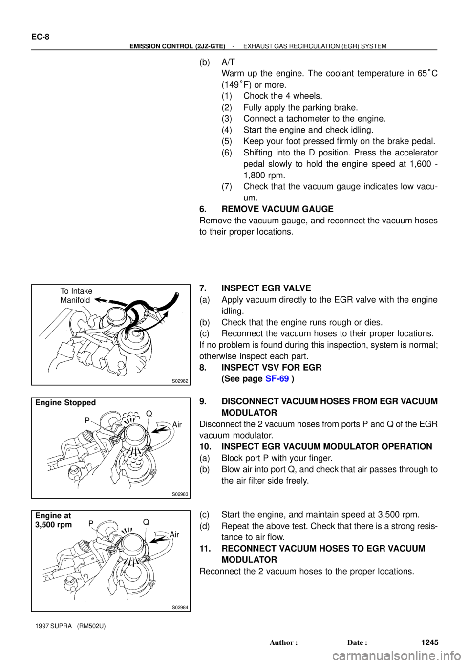
7. INSPECT EGR VALVE
(a) Apply vacuum directly to the EGR valve with the engine
idling.
(b) Check that the engine runs rough or dies.
(c) Reconnect the vacuum hoses to their proper locations.
If no problem is found during this inspection, system is normal;
otherwise inspect each part.
8. INSPECT VSV FOR EGR
(See page SF-69)
9. DISCONNECT VACUUM HOSES FROM EGR VACUUM
MODULATOR
Disconnect the 2 vacuum hoses from ports P and Q of the EGR
vacuum modulator.
10. INSPECT EGR VACUUM MODULATOR OPERATION
(a) Block port P with your finger.
(b) Blow air into port Q, and check that air passes through to
the air filter side freely.
(c) Start the engine, and maintain speed at 3,500 rpm.
(d) Repeat the above test. Check that there is a strong resis-
tance to air flow.
11. RECONNECT VACUUM HOSES TO EGR VACUUM
MODULATOR
Reconnect the 2 vacuum hoses to the proper locations.
Page 1321 of 1807

Z09735
B B
A
- ENGINE MECHANICAL (2JZ-GTE)ENGINE UNIT
EM-69
1174 Author�: Date�:
1997 SUPRA (RM502U)
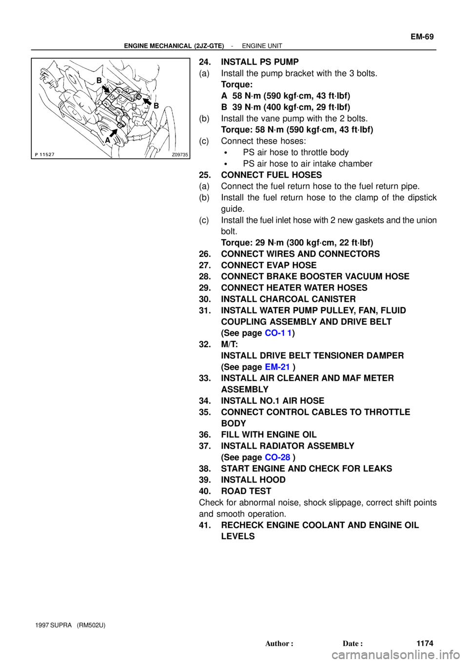
24. INSTALL PS PUMP
(a) Install the pump bracket with the 3 bolts.
Torque:
A 58 N´m (590 kgf´cm, 43 ft´lbf)
B 39 N´m (400 kgf´cm, 29 ft´lbf)
(b) Install the vane pump with the 2 bolts.
Torque: 58 N´m (590 kgf´cm, 43 ft´lbf)
(c) Connect these hoses:
�PS air hose to throttle body
�PS air hose to air intake chamber
25. CONNECT FUEL HOSES
(a) Connect the fuel return hose to the fuel return pipe.
(b) Install the fuel return hose to the clamp of the dipstick
guide.
(c) Install the fuel inlet hose with 2 new gaskets and the union
bolt.
Torque: 29 N´m (300 kgf´cm, 22 ft´lbf)
26. CONNECT WIRES AND CONNECTORS
27. CONNECT EVAP HOSE
28. CONNECT BRAKE BOOSTER VACUUM HOSE
29. CONNECT HEATER WATER HOSES
30. INSTALL CHARCOAL CANISTER
31. INSTALL WATER PUMP PULLEY, FAN, FLUID
COUPLING ASSEMBLY AND DRIVE BELT
(See page CO-1 1)
32. M/T:
INSTALL DRIVE BELT TENSIONER DAMPER
(See page EM-21)
33. INSTALL AIR CLEANER AND MAF METER
ASSEMBLY
34. INSTALL NO.1 AIR HOSE
35. CONNECT CONTROL CABLES TO THROTTLE
BODY
36. FILL WITH ENGINE OIL
37. INSTALL RADIATOR ASSEMBLY
(See page CO-28)
38. START ENGINE AND CHECK FOR LEAKS
39. INSTALL HOOD
40. ROAD TEST
Check for abnormal noise, shock slippage, correct shift points
and smooth operation.
41. RECHECK ENGINE COOLANT AND ENGINE OIL
LEVELS
Page 1322 of 1807

EM0AN-03
S00635
Piston Ring (No.1 Compression)
Piston Ring (Side Rail and Expander)
� Snap RingPiston Ring (No.2 Compression)
� Snap RingPistonPiston Pin
� Connecting Rod Bushing
Connecting Rod
Connecting Rod Bearing
Connecting
Rod Cap
No.2 Water Bypass
Pipe with Hose
� Gasket
x 8
Flywheel (M/T)
Engine Coolant Drain Plug
Rear Oil Seal
Retainer
� Oil Seal
x 6x 8 �
Front Spacer
Rear Plate
Drive Plate (A/T)
Crankshaft Position Sensor
Cylinder Block� O-Ring
Water Pump
x 6
Generator
�
� Crankshaft
Front Oil Sealx 9 Oil Pump
Idler Pulley
� O-RingKnock Sensor 2
Fuel Pipe Supportx 6
Oil Nozzle
Knock
Sensor 1
LH Engine Mounting
Bracket and
Insulator Assembly
Crankshaft
� O-Ring
Oil Cooler
Oil Filter� Gasket � O-Ring
Oil Filter Bracket
� O-RingMain Bearing
Crankshaft Thrust
Washer
Main Bearing Cap
Turbo Oil
Outlet Pipe
� Gasket
No.1 Oil Pan
� Gasket
x 16x 6
x 5
x 14
� GasketRH Engine Mounting
Bracket and Insulator
Assembly
Oil Level Sensor
Oil Strainer
No.2 Oil Pan
Drain Plug
� Non-reusable part
� Precoated part
� Gasket
EM-70
- ENGINE MECHANICAL (2JZ-GTE)CYLINDER BLOCK
1175 Author�: Date�:
1997 SUPRA (RM502U)
CYLINDER BLOCK
COMPONENTS
Page 1323 of 1807

EM0AO-02
P02447
P04467
P12207Knock Sensor
Union for Oil Cooler HoseOil Pressure
Switch
SST
- ENGINE MECHANICAL (2JZ-GTE)CYLINDER BLOCK
EM-71
1176 Author�: Date�:
1997 SUPRA (RM502U)
DISASSEMBLY
1. M/T:
REMOVE FLYWHEEL
2. A/T:
REMOVE DRIVE PLATE
3. INSTALL ENGINE TO ENGINE STAND FOR
DISASSEMBLY
4. REMOVE GENERATOR
5. REMOVE TIMING BELT AND PULLEYS
(See page EM-15)
6. REMOVE CYLINDER HEAD (See page EM-29)
7. REMOVE OIL COOLER (See page LU-20)
8. REMOVE NO.2 WATER BYPASS PIPE WITH HOSE
Remove the 2 bolts, 2 nuts, water bypass pipe and gasket.
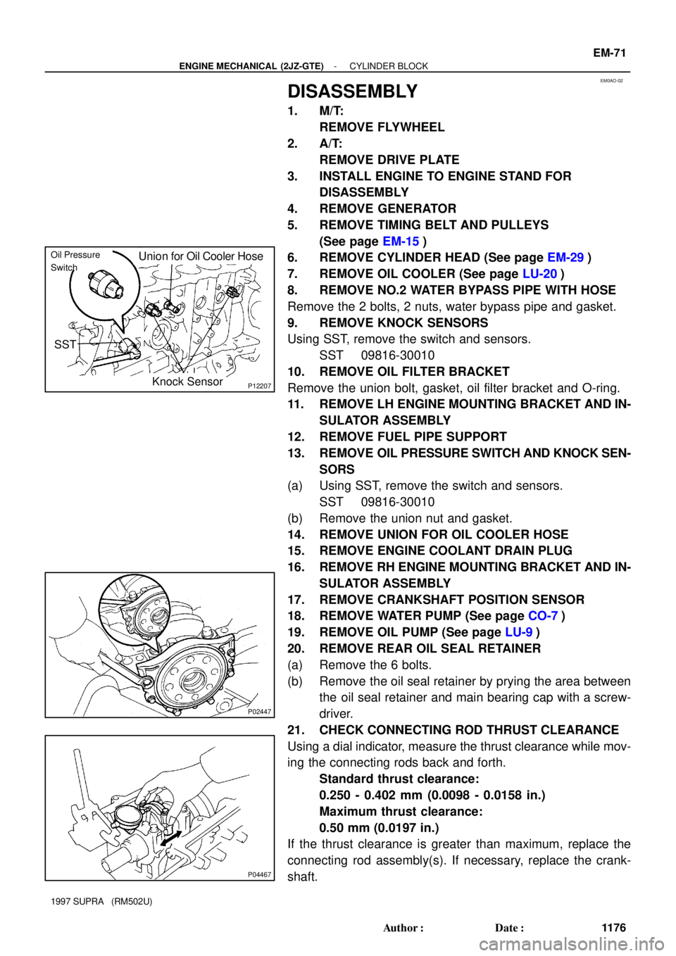
9. REMOVE KNOCK SENSORS
Using SST, remove the switch and sensors.
SST 09816-30010
10. REMOVE OIL FILTER BRACKET
Remove the union bolt, gasket, oil filter bracket and O-ring.
11. REMOVE LH ENGINE MOUNTING BRACKET AND IN-
SULATOR ASSEMBLY
12. REMOVE FUEL PIPE SUPPORT
13. REMOVE OIL PRESSURE SWITCH AND KNOCK SEN-
SORS
(a) Using SST, remove the switch and sensors.
SST 09816-30010
(b) Remove the union nut and gasket.
14. REMOVE UNION FOR OIL COOLER HOSE
15. REMOVE ENGINE COOLANT DRAIN PLUG
16. REMOVE RH ENGINE MOUNTING BRACKET AND IN-
SULATOR ASSEMBLY
17. REMOVE CRANKSHAFT POSITION SENSOR
18. REMOVE WATER PUMP (See page CO-7)
19. REMOVE OIL PUMP (See page LU-9)
20. REMOVE REAR OIL SEAL RETAINER
(a) Remove the 6 bolts.
(b) Remove the oil seal retainer by prying the area between
the oil seal retainer and main bearing cap with a screw-
driver.
21. CHECK CONNECTING ROD THRUST CLEARANCE
Using a dial indicator, measure the thrust clearance while mov-
ing the connecting rods back and forth.
Standard thrust clearance:
0.250 - 0.402 mm (0.0098 - 0.0158 in.)
Maximum thrust clearance:
0.50 mm (0.0197 in.)
If the thrust clearance is greater than maximum, replace the
connecting rod assembly(s). If necessary, replace the crank-
shaft.