Page 1074 of 3342

TOOTH CONTACT PATTERN
Condition Contact pattern Adjustment
Correct tooth contact
Tooth contact pattern slightly shifted
towards toe under no load rotation.
(When loaded, contact pattern moves
toward heel.)
B3M0317A
Face contact
Backlash is too large.This may cause noise and chipping at
tooth ends.
B3M0319
Increase thickness of drive pinion height
adjusting shim in order to bring drive
pinion closer to crown gear center.
B3M0323
Flank contact
Backlash is too small.This may cause noise and stepped wear
on surfaces.
B3M0320
Reduce thickness of drive pinion height
adjusting shim in order to move drive
pinion away from crown gear.
B3M0324
Toe contact
Contact area is small.This may cause chipping at toe ends.
B3M0321
Adjust as for flank contact.
B3M0324
Heel contact
Contact area is small.This may cause chipping at heel ends.
B3M0322
Adjust as for face contact.
B3M0323
: Adjusting direction of drive pinion
: Adjusting direction of crown gear
36
3-4SERVICE PROCEDURE
2. Rear Differential
Page 1075 of 3342
 Install rear cover and tighten bolts to specified torque.
Tightening torque:
29±5 N⋅m (3.0±0.5 kg-m, 21.7±3.6 ft-lb)
F: INSTALLATION
To install, reverse the removal sequence.
1) Insta")
G3M1050
19) Install rear cover and tighten bolts to specified torque.
Tightening torque:
29±5 N⋅m (3.0±0.5 kg-m, 21.7±3.6 ft-lb)
F: INSTALLATION
To install, reverse the removal sequence.
1) Install the air breather cap tapping with a plastic ham-
mer.
CAUTION:
Be sure to install new air breather cap.
2) Position front member on body by passing it under park-
ing brake cable and securing to rear differential.
NOTE:
When installing rear differential front member, do not con-
fuse the installation sequence of the upper and lower stop-
pers.
G3M1026
3) Install DOJ of rear drive shaft into rear differential.
to 3-4 [W2A2].>
ST 28099PA090 SIDE OIL SEAL PROTECTOR
G3M1051
4) Installing procedure hereafter is in the reverse order of
removal.
5) After installation, fill differential carrier with gear oil to
the upper plug level.
CAUTION:
Apply fluid packing to plug.
Fluid packing:
THREE BOND 1205 or equivalent
Oil capacity:
0.8�(0.8 US qt, 0.7 Imp qt)
Tightening torque:
44±4 N⋅m (4.5±0.4 kg-m, 32.5±2.9 ft-lb)
37
3-4SERVICE PROCEDURE
2. Rear Differential
Page 1076 of 3342
3. Rear Differential Front Member
A: REMOVAL
1) Disconnect ground cable from battery.
2) Move selector lever or gear shift lever to“N”.
3) Release the parking brake.
4) Loosen wheel nuts.
5) Jack-up vehicle and support it with sturdy racks.
6) Remove wheels.
7) Remove rear exhaust pipe and muffler.
8) Remove rear differential front member.
NOTE:
When removing rear differential front member, work the
removal procedure as rear differential.
38
3-4SERVICE PROCEDURE
3. Rear Differential Front Member
Page 1077 of 3342
G3M1029
B: INSTALLATION
To install, reverse the removal sequence.
1) Position front member on body by passing it under park-
ing brake cable and securing to rear differential.
G3M0101
NOTE:
When installing rear differential front member, do not con-
fuse the installation sequence of the stopper.
G3M1026
2) Insert DOJ of rear drive shaft into rear differential.
ST 28099PA090 SIDE OIL SEAL PROTECTOR
CAUTION:
Before inserting, replace the differential side oil seal
and the circlip at the end of the spline shaft with a new
one.
3) Installing procedure hereafter is in the reverse order of
removal.
39
3-4SERVICE PROCEDURE
3. Rear Differential Front Member
Page 1081 of 3342
1. Suspension
A: SPECIFICATIONS
1. STABILIZER
ModelBar dia. mm (in)
Front Rear
Sedan2200 cc 19 (0.75) 15 (0.59)
2500 cc 20 (0.79) 16 (0.63)
Wagon2200 cc 19 (0.75) 15 (0.59)
2500 cc 20 (0.79) 16 (0.63)
OUTBACK2200 cc 20 (0.79) 18 (0.71)
2500 cc 20 (0.79) 18 (0.71)
B: WHEEL ALIGNMENT
Sedan Wagon OUTBACK
FWD AWD FWD AWD AWD
FrontCamber
(tolerance: ±0°30′)�0°05′�0°05′�0°05′�0°05′0°20′
Caster
(tolerance: ±1°)3°05′3°05′3°05′3°05′2°50′
Toe-in mm (in) 0±3 (0±0.12) Total toe angle: 0°±20′
Kingpin angle (tolerance: ±1°) 14°15′14°15′14°15′14°15′13°30′
Wheel arch height
[tolerance:
+12
�24mm (+0.47
� 0.94in)] mm (in)385 (15.16) 385 (15.16) 385 (15.16) 385 (15.16) 420 (16.54)
RearCamber
(tolerance: ±0°45′)�0°55′�1° �0°45′�0°55′�0°35′
Toe-in mm (in) 0±3 (0±0.12) Total toe angle: 0°±20′
Wheel arch height
[tolerance:
+12
�24mm (+0.47
� 0.94in)] mm (in)369 (14.53) 369 (14.53) 379 (14.92) 379 (14.92) 419 (16.50)
Thrust angle 0°±20′
2
4-1SPECIFICATIONS AND SERVICE DATA
1. Suspension
Page 1082 of 3342
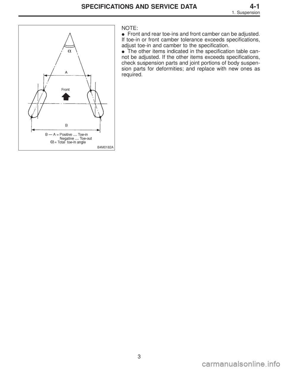
B4M0182A
NOTE:
�Front and rear toe-ins and front camber can be adjusted.
If toe-in or front camber tolerance exceeds specifications,
adjust toe-in and camber to the specification.
�The other items indicated in the specification table can-
not be adjusted. If the other items exceeds specifications,
check suspension parts and joint portions of body suspen-
sion parts for deformities; and replace with new ones as
required.
3
4-1SPECIFICATIONS AND SERVICE DATA
1. Suspension
Page 1086 of 3342
1. On-car Services
A: WHEEL ALIGNMENT
Check, adjust and/or measure wheel alignment in accor-
dance with procedures indicated below:
1. Wheel arch height (Front and rear)
2. Camber (Front and rear)
3. Caster (Front)
4. Front toe-in
5. Rear toe-in
6. Thrust angle (Rear)
7. Wheel steering angle
�
�
�
�
�
�
7
4-1SERVICE PROCEDURE
1. On-car Services
Page 1087 of 3342
1. WHEEL ARCH HEIGHT
1) Adjust tire pressure to specifications.
2) Set vehicle under“curb weight”conditions. (Empty lug-
gage compartment, install spare tire, jack, service tools,
and top up fuel tank.)
3) Set steering wheel in a wheel-forward position.
4) Suspend thread from wheel arch (point“A”in figure
below) to determine a point directly above center of
spindle.
5) Measure distance between measuring point and center
of spindle.
B4M0566A
VehiclesSpecified wheel arch height mm (in)
Front Rear
SedanFWD 385
+12
�24(15.16+0.47
�0.94) 369+12
�24(14.53+0.47
�0.94)
AWD 385
+12
�24(15.16+0.47
�0.94) 369+12
�24(14.53+0.47
�0.94)
WagonFWD 385
+12
�24(15.16+0.47
�0.94) 379+12
�24(14.92+0.47
�0.94)
AWD 385
+12
�24(15.16+0.47
�0.94) 379+12
�24(14.92+0.47
�0.94)
OUTBACK AWD 420
+12
�24(16.54+0.47
�0.94) 419+12
�24(16.50+0.47
�0.94)
8
4-1SERVICE PROCEDURE
1. On-car Services
 Disconnect ground cable from battery.
2) Move selector lever or gear shift lever to“N”.
3) Release the parking brake.
4) Loosen wheel nuts.
5) Jack-")
 Position front member on body by passing it under park-
ing brake cable and securing to rear differential.
G3M0101
NOTE:
When insta")

Front Rear
Sedan2200 cc 19 (0.75) 15 (0.59)
2500 cc 20 (0.79) 16 (0.63)
Wagon2200 cc 19 (0.75) 15 (0.59)
2500 cc 20 (0.79) 16 (0.63)")

2. Camber (Front and rear)
3.")
 Adjust tire pressure to specifications.
2) Set vehicle under“curb weight”conditions. (Empty lug-
gage compartment, install spare tire, jack, service tools,
and top up fuel")