Page 1058 of 3342
G3M0053
11) Remove heat sealed cover.
12) Remove clamps and bracket of parking brake cable.
13) Remove crossmember reinforcement lower (AWD
Sedan only).
G3M1020
14) Remove DOJ of rear drive shaft from rear differential
using ST.
ST 28099PA100 DRIVE SHAFT REMOVER
G3M1022
15) Secure rear drive shaft to rear crossmember using
wire.
G3M0054
16) Remove lower differential bracket.
G3M0055
17) Support rear differential with transmission jack.
20
3-4SERVICE PROCEDURE
2. Rear Differential
Page 1059 of 3342
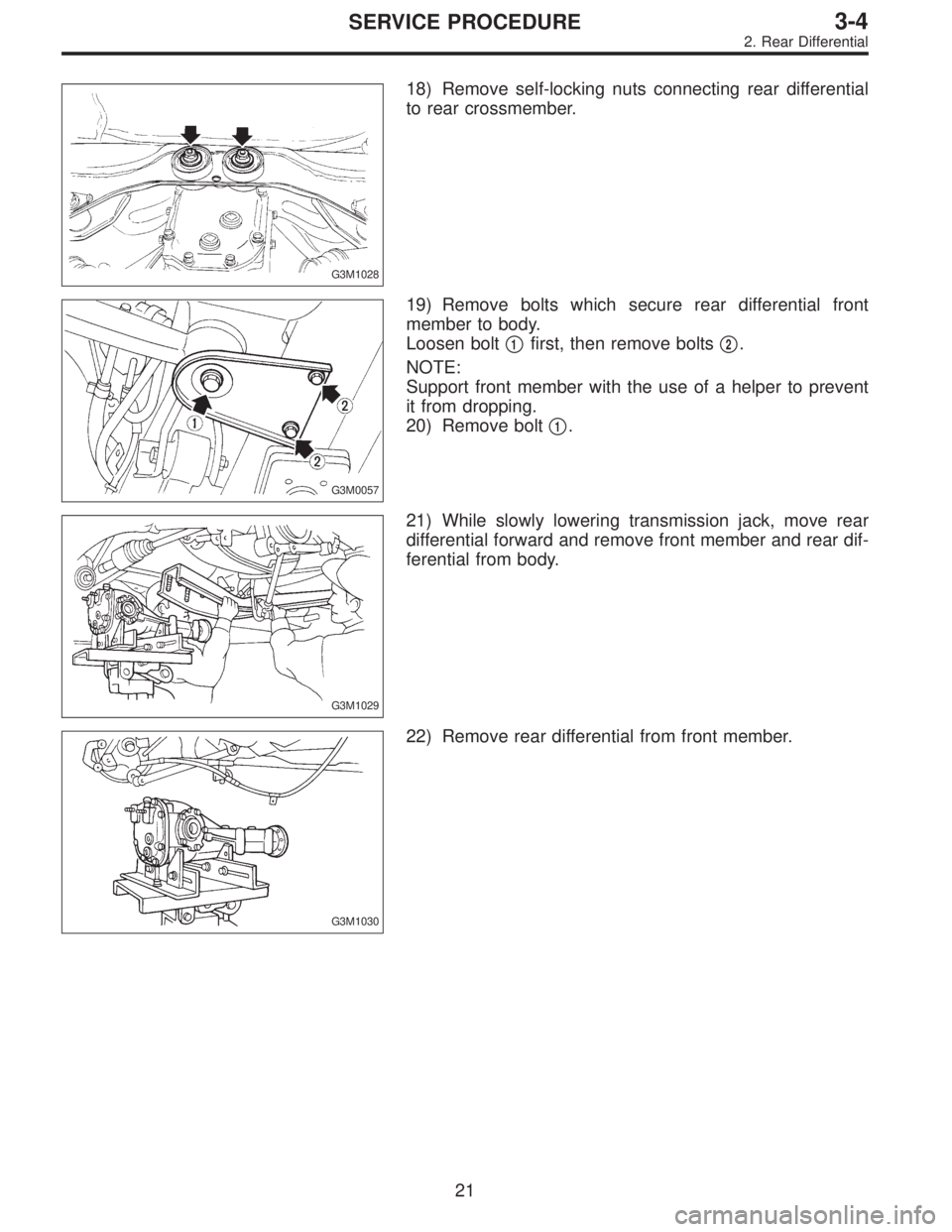
G3M1028
18) Remove self-locking nuts connecting rear differential
to rear crossmember.
G3M0057
19) Remove bolts which secure rear differential front
member to body.
Loosen bolt�
1first, then remove bolts�2.
NOTE:
Support front member with the use of a helper to prevent
it from dropping.
20) Remove bolt�
1.
G3M1029
21) While slowly lowering transmission jack, move rear
differential forward and remove front member and rear dif-
ferential from body.
G3M1030
22) Remove rear differential from front member.
21
3-4SERVICE PROCEDURE
2. Rear Differential
Page 1060 of 3342
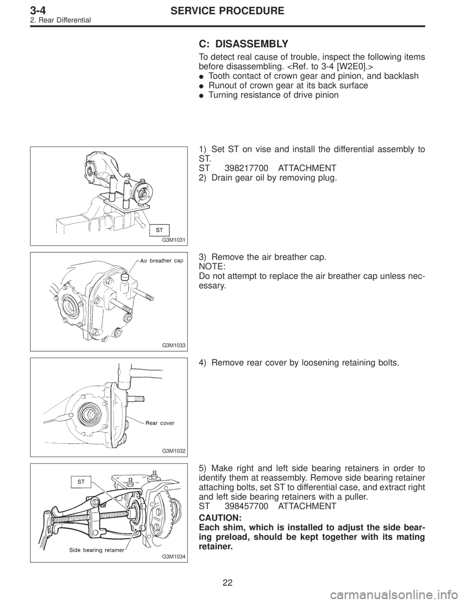
C: DISASSEMBLY
To detect real cause of trouble, inspect the following items
before disassembling.
�Tooth contact of crown gear and pinion, and backlash
�Runout of crown gear at its back surface
�Turning resistance of drive pinion
G3M1031
1) Set ST on vise and install the differential assembly to
ST.
ST 398217700 ATTACHMENT
2) Drain gear oil by removing plug.
G3M1033
3) Remove the air breather cap.
NOTE:
Do not attempt to replace the air breather cap unless nec-
essary.
G3M1032
4) Remove rear cover by loosening retaining bolts.
G3M1034
5) Make right and left side bearing retainers in order to
identify them at reassembly. Remove side bearing retainer
attaching bolts, set ST to differential case, and extract right
and left side bearing retainers with a puller.
ST 398457700 ATTACHMENT
CAUTION:
Each shim, which is installed to adjust the side bear-
ing preload, should be kept together with its mating
retainer.
22
3-4SERVICE PROCEDURE
2. Rear Differential
Page 1061 of 3342
G3M1035
6) Pull out differential assembly from differential carrier.
CAUTION:
Be careful not to hit the teeth against the case.
G3M1036
7) When replacing side bearing, pull bearing cup from side
bearing retainer using ST.
ST 398527700 PULLER ASSY
G3M0068
8) Extract bearing cone with ST.
CAUTION:
Do not attempt to disassemble the parts unless neces-
sary.
NOTE:
�Set puller so that its claw catch the edge of the bearing
cone.
�Never mix up the right and left hand bearing cups and
cones.
ST 399527700 PULLER SET
G3M0069
9) Remove crown gear by loosening crown gear bolts.
CAUTION:
Further disassembling is not allowed.
B3M0133
10) Drive out pinion shaft lock pin from crown gear side.
NOTE:
The lock pin is staked at the pin hole end on the differen-
tial carrier; do not drive it out forcibly before unstaking it.
ST 899904100 STRAIGHT PIN REMOVER
23
3-4SERVICE PROCEDURE
2. Rear Differential
Page 1062 of 3342
G3M1052
11) Hold companion flange with ST and remove drive pin-
ion nut.
ST 498427200 FLANGE WRENCH
G3M0073
12) Extract the companion flange with a puller.
G3M0074
13) Press the end of drive pinion shaft and extract it
together with rear bearing cone, preload adjusting spacer
and washer.
NOTE:
Hold the drive pinion so as not to drop it.
ST 398467700 DRIFT
G3M0071
14) Draw out pinion mate shaft and remove pinion mate
gears, side gears and thrust washers.
NOTE:
The gears as well as thrust washers should be marked or
kept separated left and right, and front and rear.
G3M0072
15) Hold companion flange with ST and remove drive pin-
ion nut.
ST 498427200 FLANGE WRENCH
24
3-4SERVICE PROCEDURE
2. Rear Differential
Page 1063 of 3342
G3M0073
16) Extract the companion flange with a puller.
G3M0074
17) Press the end of drive pinion shaft and extract it
together with rear bearing cone, preload adjusting spacer
and washer.
NOTE:
Hold the drive pinion so as not to drop it.
ST 398467700 DRIFT
G3M0075
18) Remove rear bearing cone from drive pinion by sup-
porting cone with ST.
NOTE:
Place the replacer so that its center-recessed side faces
the pinion gear.
ST 498515500 REPLACER
G3M0076
19) Remove front oil seal from differential carrier using ST.
ST 398527700 PULLER ASSY
G3M0077
20) Remove pilot bearing together with front bearing cone
using ST.
ST 398467700 DRIFT
25
3-4SERVICE PROCEDURE
2. Rear Differential
Page 1064 of 3342
 When replacing bearings, tap front bearing cup and
rear bearing cup in this order out of case by using a brass
bar.
D: INSPECTION
Wash all the disassembled parts clean, and examine them
fo")
G3M0078
21) When replacing bearings, tap front bearing cup and
rear bearing cup in this order out of case by using a brass
bar.
D: INSPECTION
Wash all the disassembled parts clean, and examine them
for wear, damage, or other defects. Repair or replace
defective parts as necessary.
1) Crown gear and drive pinion
(1) If abnormal tooth contact is evident, find out the
cause and adjust to give correct tooth contact at
assembly. Replace the gear if excessively worn or inca-
pable of adjustment.
(2) If crack, score, or seizure is evident, replace as a
set. Slight damage of tooth can be corrected by oil
stone or the like.
2) Side gear and pinion mate gear
(1) Replace if crack, score, or other defects are evident
on tooth surface.
(2) Replace if thrust washer contacting surface is worn
or seized. Slight damage of the surface can be cor-
rected by oil stone or the like.
3) Bearing
Replace if seizure, peeling, wear, rust, dragging during
rotation, abnormal noise or other defect is evident.
4) Thrust washers of side gear and pinion mate gear
Replace if seizure, flaw, abnormal wear or other defect is
evident.
5) Oil seal
Replace if deformed or damaged, and at every disassem-
bling.
6) Differential carrier
Replace if the bearing bores are worn or damaged.
7) Differential case
Replace if its sliding surfaces are worn or cracked.
8) Companion flange
Replace if the oil seal lip contacting surfaces have flaws.
26
3-4SERVICE PROCEDURE
2. Rear Differential
Page 1065 of 3342
 Precautions for assembling
(1) Assemble in the reverse order of disassembling.
(2) Check and adjust each part during assembly.
(3) Keep the shims and washers in order, so that they
are")
E: ASSEMBLY
1) Precautions for assembling
(1) Assemble in the reverse order of disassembling.
(2) Check and adjust each part during assembly.
(3) Keep the shims and washers in order, so that they
are not misinstalled.
(4) Thoroughly clean the surfaces on which the shims,
washers and bearings are to be installed.
(5) Apply gear oil when installing the bearings and
thrust washers.
(6) Be careful not to mix up the right and left hand cups
of the bearings.
G3M0079
(7) Replace the oil seal with new one at every disas-
sembly. Apply chassis grease between the lips when
installing the oil seal.
G3M1037
2) Adjusting preload for front and rear bearings
Adjust the bearing preload with spacer and washer
between front and rear bearings. Pinion height adjusting
washer are not affected by this adjustment. The adjustment
must be carried out without oil seal inserted.
(1) Press rear bearing race into differential carrier with
ST1 and ST2.
ST1 398477701 HANDLE
ST2 398427703 DRIFT 2
G3M0081
(2) Insert ST1 into case with pinion height adjusting
washer and rear bearing cone fitted onto it.
CAUTION:
�Re-use the used washer if not deformed.
�Use a new rear bearing cone.
(3) Then install preload adjusting spacer and washer,
front bearing cone, ST2, companion flange, and washer
and drive pinion nut.
ST1 398507702 DUMMY SHAFT
ST2 398507703 DUMMY COLLAR
27
3-4SERVICE PROCEDURE
2. Rear Differential
 Remove heat sealed cover.
12) Remove clamps and bracket of parking brake cable.
13) Remove crossmember reinforcement lower (AWD
Sedan only).
G3M1020
14) Remove DOJ of rear drive shaft from")
 Pull out differential assembly from differential carrier.
CAUTION:
Be careful not to hit the teeth against the case.
G3M1036
7) When replacing side bearing, pull bearing cup from side
beari")
 Hold companion flange with ST and remove drive pin-
ion nut.
ST 498427200 FLANGE WRENCH
G3M0073
12) Extract the companion flange with a puller.
G3M0074
13) Press the end of drive pinion sh")
 Extract the companion flange with a puller.
G3M0074
17) Press the end of drive pinion shaft and extract it
together with rear bearing cone, preload adjusting spacer
and washer.
NOTE:
Hold")