Page 1019 of 3342
 Check the drive plate facing for wear and damage.
2) Check the snap ring for wear, return spring for perma-
nent set and breakage, and spring retainer for deformation.
3) Check the la")
B: INSPECTION
1) Check the drive plate facing for wear and damage.
2) Check the snap ring for wear, return spring for perma-
nent set and breakage, and spring retainer for deformation.
3) Check the lathe cut ring for damage.
G3M0498
C: ASSEMBLY
1) Install the lathe cut seal ring to the I.D./O.D. of the
transfer clutch piston.
G3M0499
2) Install piston.
(1) Connect piston to rear drive shaft (until it reaches
hole in valve body).
(2) Install spring retainer to piston.
(3) Using ST1, ST2 and ST3, attach transfer piston
seal to ST2.
ST1 499247400 INSTALLER
ST2 499257400 PISTON GUIDE
ST3 498267400 TABLE
CAUTION:
Be careful not to tilt transfer piston seal.
G3M0500
(4) Place ST3 onto rear drive shaft so that spring can
be inserted into hole in transfer piston seal.
(5) Attach ST2 to rear drive shaft. Using ST1, press
into place.
ST1 499247400 INSTALLER
ST2 499257300 SNAP RING OUTER GUIDE
ST3 499257400 PISTON GUIDE
CAUTION:
Do not allow lip of transfer piston seal to fold back.
11 0
3-2SERVICE PROCEDURE
15. Transfer Clutch
Page 1020 of 3342
G3M0501
3) Install the driven plates, drive plates, and pressure
plate, and secure with a snap ring with ST1, ST2 and a
press.
ST1 398673600 COMPRESSOR
ST2 498627000 SEAT
G3M0502
4) Apply compressed air to see if the assembled parts
move smoothly.
G3M0503
5) Check the clearance.
Standard value:
0.2—0.6 mm (0.008—0.024 in)
Allowable limit:
1.6 mm (0.063 in)
If the clearance is not within the specified range, select a
proper pressure plate.
NOTE:
Before measuring clearance, place the same thickness of
shim on both sides to prevent pressure plate from tilting.
�Available pressure platesPart No. Thickness mm (in)
31593AA151
31593AA161
31593AA171
31593AA1813.3 (0.130)
3.7 (0.146)
4.1 (0.161)
4.5 (0.177)
G3M0505
6) Press-fit the ball bearing with ST.
ST 899580100 INSTALLER
111
3-2SERVICE PROCEDURE
15. Transfer Clutch
Page 1021 of 3342
G3M0505
7) Coat the seal ring with vaseline, and install it in the seal
ring groove of the shaft.
CAUTION:
Do not expand the seal ring excessively when install-
ing.
ST 899580100 INSTALLER
G3M0913
16. Transfer Valve Body
A: DISASSEMBLY
1) Remove the plate. Then remove the spring and pilot
valve together.
2) Remove the straight pin and pry out the plug with a
screwdriver. Then extract the spring and transfer clutch
valve together.
CAUTION:
Be careful not to damage the valve and valve body.
B: INSPECTION
Check each component for harmful cuts, damage, or other
faults.
C: ASSEMBLY
To assemble, reverse the removal sequence.
NOTE:
Make sure the valve slides smoothly after assembling.
11 2
3-2SERVICE PROCEDURE
15. Transfer Clutch - 16. Transfer Valve Body
Page 1022 of 3342
G3M0505
7) Coat the seal ring with vaseline, and install it in the seal
ring groove of the shaft.
CAUTION:
Do not expand the seal ring excessively when install-
ing.
ST 899580100 INSTALLER
G3M0913
16. Transfer Valve Body
A: DISASSEMBLY
1) Remove the plate. Then remove the spring and pilot
valve together.
2) Remove the straight pin and pry out the plug with a
screwdriver. Then extract the spring and transfer clutch
valve together.
CAUTION:
Be careful not to damage the valve and valve body.
B: INSPECTION
Check each component for harmful cuts, damage, or other
faults.
C: ASSEMBLY
To assemble, reverse the removal sequence.
NOTE:
Make sure the valve slides smoothly after assembling.
11 2
3-2SERVICE PROCEDURE
15. Transfer Clutch - 16. Transfer Valve Body
Page 1023 of 3342
G6M0095
17. Transmission Control Module
A: REMOVAL
1. LHD MODEL
1) Disconnect battery ground cable.
B3M0377A
2) Remove lower cover and then disconnect connector.
B3M0443A
3) Remove transmission control module.
�
1Transmission control module
�
2Cruise control module
�
3Pedal bracket
4) Disconnect connectors from transmission control mod-
ule.
G6M0095
2. RHD MODEL
1) Disconnect battery ground cable.
2) Remove lower cover and then disconnect connector.
B3M0445A
3) Remove transmission control module.
�
1Transmission control module
�
2Column shaft
4) Disconnect connectors from transmission control mod-
ule.
11 3
3-2SERVICE PROCEDURE
17. Transmission Control Module
Page 1024 of 3342
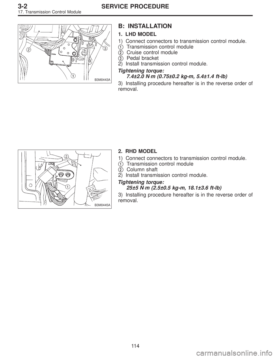
B3M0443A
B: INSTALLATION
1. LHD MODEL
1) Connect connectors to transmission control module.
�
1Transmission control module
�
2Cruise control module
�
3Pedal bracket
2) Install transmission control module.
Tightening torque:
7.4±2.0 N⋅m (0.75±0.2 kg-m, 5.4±1.4 ft-lb)
3) Installing procedure hereafter is in the reverse order of
removal.
B3M0445A
2. RHD MODEL
1) Connect connectors to transmission control module.
�
1Transmission control module
�
2Column shaft
2) Install transmission control module.
Tightening torque:
25±5 N⋅m (2.5±0.5 kg-m, 18.1±3.6 ft-lb)
3) Installing procedure hereafter is in the reverse order of
removal.
11 4
3-2SERVICE PROCEDURE
17. Transmission Control Module
Page 1029 of 3342
1. Manual Transmission
A: REMOVAL
1) Remove console box.
B3M0615
2) Remove boot plate from the body.
G3M0680
3) Remove the spring between the joint and bracket.
G3M0681
4) Remove stay from bracket.
B3M0616A
5) Remove rod from joint.
6
3-3SERVICE PROCEDURE
1. Manual Transmission
Page 1030 of 3342
G3M0683
6) Remove gearshift lever.
G3M0684
7) Remove the exhaust cover and remove cushion rubber
from the body.
B3M0617A
B: DISASSEMBLY
1) Disconnect locking wire.
B3M0618A
2) Remove rod from gearshift lever.
B3M0619A
3) Remove snap ring, then disconnect gearshift lever from
stay.
4) Remove boot from gearshift lever.
7
3-3SERVICE PROCEDURE
1. Manual Transmission
 Install the driven plates, drive plates, and pressure
plate, and secure with a snap ring with ST1, ST2 and a
press.
ST1 398673600 COMPRESSOR
ST2 498627000 SEAT
G3M0502
4) Apply compressed a")
 Coat the seal ring with vaseline, and install it in the seal
ring groove of the shaft.
CAUTION:
Do not expand the seal ring excessively when install-
ing.
ST 899580100 INSTALLER
G3M0913
16.")
 Coat the seal ring with vaseline, and install it in the seal
ring groove of the shaft.
CAUTION:
Do not expand the seal ring excessively when install-
ing.
ST 899580100 INSTALLER
G3M0913
16.")
 Disconnect battery ground cable.
B3M0377A
2) Remove lower cover and then disconnect connector.
B3M0443A
3) Remove transmission contro")
![SUBARU LEGACY 1997 Service Repair Manual 1. Manual Transmission
A: REMOVAL
1) Remove console box. <Ref. to 5-4 [W1A0].>
B3M0615
2) Remove boot plate from the body.
G3M0680
3) Remove the spring between the joint and bracket.
G3M0681
4) Remove](/manual-img/17/57434/w960_57434-1028.png "SUBARU LEGACY 1997 Service Repair Manual 1. Manual Transmission
A: REMOVAL
1) Remove console box. <Ref. to 5-4 [W1A0].>
B3M0615
2) Remove boot plate from the body.
G3M0680
3) Remove the spring between the joint and bracket.
G3M0681
4) Remove")
 Remove gearshift lever.
G3M0684
7) Remove the exhaust cover and remove cushion rubber
from the body.
B3M0617A
B: DISASSEMBLY
1) Disconnect locking wire.
B3M0618A
2) Remove rod from gearshif")