Page 1039 of 3342
 After completion of fitting, make sure that the selector
lever operates smoothly all across the operating range.
11) Connect the harnesses and check the following items.
(1) The engine starts oper")
10) After completion of fitting, make sure that the selector
lever operates smoothly all across the operating range.
11) Connect the harnesses and check the following items.
(1) The engine starts operating when selector lever is
in position“P”, but not in other positions.
(2) The back-up light is lit when the selector lever is in
position“R”, but not in other positions.
B3M0348A
12) Check selector lever operation.
WARNING:
Stop the engine while checking operation of selector
lever.
(1) Check that selector lever does not move from“N”
to“R”without pushing the button.
(2) Check that selector lever does not move from“R”
to“P”without pushing the button.
(3) Check that selector lever does not move from“P”
to“R”without pushing the button and the brake pedal
depressed. [With ignition key set at“ON”.]
(4) Check that selector lever does not move from“3”to
“2”without pushing the button.
13) Check shift-lock system.
(1) Ensure ignition switch rotates from“ACC”to
“LOCK”when the selector lever is set at“P”. Also check
that ignition key can be removed from the“LOCK”posi-
tion only.
(2) Ensure selector lever moves from“P”to any other
position when the brake pedal is depressed with igni-
tion key set at“ON”or“START”.
16
3-3SERVICE PROCEDURE
2. Automatic Transmission
Page 1040 of 3342
1. AWD System
A. SPECIFICATIONS
1. REAR FINAL REDUCTION GEAR RATIO
Type of gearHypoid
MT AT
2200 cc 2500 cc 2200 cc 2500 cc
Gear ratio
(Number of
gear teeth)3.900
(39/10)4 . 111
(37/9)4.444
(40/9)
Oil capacity 0.8�(0.8 US qt, 0.7 Imp qt)
Rear
differential
gear oilGL-5
2. PROPELLER SHAFT
Front propeller shaft
Joint-to-joint length:
L mm (in)AT 539 (21.22)
MT 598 (23.54)
Outside dia. of tube
mm (in)D
163.5 (2.500)
D
257.0 (2.244)
G3M0014
2
3-4SPECIFICATIONS AND SERVICE DATA
1. AWD System
Page 1041 of 3342
H3M1180A
B: IDENTIFICATION
When replacing a rear differential assembly, select the cor-
rect one according to the following table.
CAUTION:
Using the different rear differential assembly causes
the drive line and tires to “drag” or emit abnormal
noise when AWD is selected.
Gear ratio Part number Stamp on rear differential
2200 cc
MT3.900 27011AA330
B3M0124
2200 cc
AT
4.111 27011AA340
B3M0127
2500 cc
MT
2500 cc
AT4.444 27011AA410
B3M0421
3
3-4SPECIFICATIONS AND SERVICE DATA
1. AWD System
Page 1042 of 3342
C: SERVICE DATA
Front and rear bearing preload at
companion flange bolt holeNew bearing19.6 — 28.4 N
(2.0 — 2.9 kg, 4.4 —6.4 lb)
Used bearing8.34 — 16.67 N
(0.85 — 1.70 kg, 1.87 — 3.75 lb)
Preload adjusting washer lengthPart No. Length
383705200 2.59 mm (0.1020 in)
383715200 2.57 mm (0.1012 in)
383725200 2.55 mm (0.1004 in)
383735200 2.53 mm (0.0996 in)
383745200 2.51 mm (0.0988 in)
383755200 2.49 mm (0.0980 in)
383765200 2.47 mm (0.0972 in)
383775200 2.45 mm (0.0965 in)
383785200 2.43 mm (0.0957 in)
383795200 2.41 mm (0.0949 in)
383805200 2.39 mm (0.0941 in)
383815200 2.37 mm (0.0933 in)
383825200 2.35 mm (0.0925 in)
383835200 2.33 mm (0.0917 in)
383845200 2.31 mm (0.0909 in)
Preload adjusting spacer lengthPart No. Length
383695201 56.2 mm (2.213 in)
383695202 56.4 mm (2.220 in)
383695203 56.6 mm (2.228 in)
383695204 56.8 mm (2.236 in)
383695205 57.0 mm (2.244 in)
383695206 57.2 mm (2.252 in)
4
3-4SPECIFICATIONS AND SERVICE DATA
1. AWD System
Page 1043 of 3342

383505200 3.12 mm (0.1228 in)
383515200 3.15 mm (0.1240 in)
383525200 3.18 mm (0.1252 in)
383535200 3.21 mm (0.12")
Pinion height adjusting shim thicknessPart No. Thickness
383495200 3.09 mm (0.1217 in)
383505200 3.12 mm (0.1228 in)
383515200 3.15 mm (0.1240 in)
383525200 3.18 mm (0.1252 in)
383535200 3.21 mm (0.1264 in)
383545200 3.24 mm (0.1276 in)
383555200 3.27 mm (0.1287 in)
383565200 3.30 mm (0.1299 in)
383575200 3.33 mm (0.1311 in)
383585200 3.36 mm (0.1323 in)
383595200 3.39 mm (0.1335 in)
383605200 3.42 mm (0.1346 in)
383615200 3.45 mm (0.1358 in)
383625200 3.48 mm (0.1370 in)
383635200 3.51 mm (0.1382 in)
383645200 3.54 mm (0.1394 in)
383655200 3.57 mm (0.1406 in)
383665200 3.60 mm (0.1417 in)
383675200 3.63 mm (0.1429 in)
383685200 3.66 mm (0.1441 in)
Side bearing standard width—20.00 mm (0.7874 in)
Side bearing retainer shim thicknessPart No. Thickness
383475201 0.20 mm (0.0079 in)
383475202 0.25 mm (0.0098 in)
383475203 0.30 mm (0.0118 in)
383475204 0.40 mm (0.0157 in)
383475205 0.50 mm (0.0197 in)
Crown gear to drive pinion backlash
Limit0.10—0.20 mm (0.0039—0.0079 in)
Crown gear runout on its back surface 0.05 mm (0.0020 in)
Oil capacity0.8�(0.8 US qt, 0.7 Imp qt)
5
3-4SPECIFICATIONS AND SERVICE DATA
1. AWD System
Page 1047 of 3342
 Joints and connections
Check for any looseness of yoke flange connecting bolts
and center")
1. Propeller Shaft
A: ON-CAR SERVICE
Check the following points with propeller shaft installed in
vehicle.
1) Joints and connections
Check for any looseness of yoke flange connecting bolts
and center bearing retaining bolts.
G3M0019
2) Splines and bearing locations
Turn propeller shaft by hand to see if abnormal free play
exists at splines. Also move yokes to see if abnormal free
play exists at spiders and bearings.
G3M0020
3) Runout of propeller shaft
Turn rear wheels by hand to check for“runout”of propel-
ler shaft.
Runout:
Limit 0.6 mm (0.024 in)
NOTE:
Measure runout with a dial gauge at the center of front and
rear propeller shaft tubes.
G3M0255
4) Center bearing free play
While holding propeller shaft near center bearing with your
hand, move it up and down, and left and right to check for
any abnormal bearing free play.
B: REMOVAL
NOTE:
Before removing propeller shaft, wrap metal parts with a
cloth or rubber material.
1) Disconnect ground cable from battery.
2) Move selector lever or gear shift lever to“N”.
3) Release the parking brake.
4) Jack-up vehicle and support it with sturdy racks.
5) Remove rear exhaust pipe and muffler.
9
3-4SERVICE PROCEDURE
1. Propeller Shaft
Page 1048 of 3342
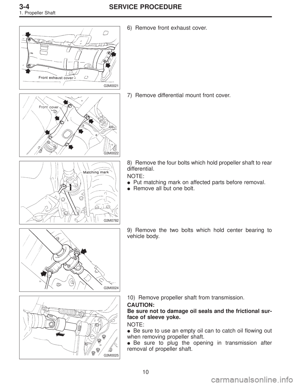
G3M0021
6) Remove front exhaust cover.
G3M0022
7) Remove differential mount front cover.
G3M0782
8) Remove the four bolts which hold propeller shaft to rear
differential.
NOTE:
�Put matching mark on affected parts before removal.
�Remove all but one bolt.
G3M0024
9) Remove the two bolts which hold center bearing to
vehicle body.
G3M0025
10) Remove propeller shaft from transmission.
CAUTION:
Be sure not to damage oil seals and the frictional sur-
face of sleeve yoke.
NOTE:
�Be sure to use an empty oil can to catch oil flowing out
when removing propeller shaft.
�Be sure to plug the opening in transmission after
removal of propeller shaft.
10
3-4SERVICE PROCEDURE
1. Propeller Shaft
Page 1049 of 3342
G3M0026
11) Install the extension cap to transmission.
G3M0027
C: DISASSEMBLY
Before removing center bearing, check its condition. If it
does not operate smoothly or if there is any free play or
leakage, remove as follows:
1) Put matching marks on affected parts.
G3M0028
2) Remove bolts which hold front propeller shaft to rear
propeller shaft.
G3M0029
3) Place companion flange in a vise and remove stake nut.
CAUTION:
Be sure not to hold propeller shaft pipe portion in the
vise.
G3M0030
4) Drive out companion flange with a puller or press.
NOTE:
Before disassembling, put matching mark on affected
parts.
11
3-4SERVICE PROCEDURE
1. Propeller Shaft
3.900
(39/10)4 . 111
(37/9)4.444
(40/9)
Oil")


Used bearing8.34 — 16.67 N
(0.85 — 1.70 kg, 1.87 — 3.75 lb)")
 Install the extension cap to transmission.
G3M0027
C: DISASSEMBLY
Before removing center bearing, check its condition. If it
does not operate smoothly or if there is any free play or
leaka")