Page 1104 of 3342
 Pull the piston rod fully upward, and install rubber seat
and spring seat.
NOTE:
Ensure that upper spring seat is positioned with“OUT”
mark facing outward.
8) Install strut mount to the")
G4M0511
7) Pull the piston rod fully upward, and install rubber seat
and spring seat.
NOTE:
Ensure that upper spring seat is positioned with“OUT”
mark facing outward.
8) Install strut mount to the piston rod, and tighten the
self-locking nut temporarily.
CAUTION:
Be sure to use a new self-locking nut.
G4M0507
9) Using hexagon wrench to prevent strut rod from turning,
tighten self-locking nut with ST.
Tightening torque:
54±5 N⋅m (5.5±0.5 kg-m, 39.8±3.6 ft-lb)
ST 927760000 STRUT MOUNT SOCKET
10) Loosen the coil spring carefully.
E: INSTALLATION
1) Install strut mount at upper side of strut to body and
tighten with nuts.
Tightening torque:
20±6 N⋅m (2.0±0.6 kg-m, 14.5±4.3 ft-lb)
2) Connect housing to lower side of strut.
3) Position aligning mark on camber adjusting bolt with
aligning mark on lower side bracket of strut.
CAUTION:
�While holding head of adjusting bolt, tighten self-
locking nut.
�Be sure to use new self-locking nut.
Tightening torque:
152±20 N⋅m (15.5±2.0 kg-m, 112±14 ft-lb)
4) Install A.B.S. sensor harness to strut. (A.B.S. equipped
models.)
Tightening torque:
152±20 N⋅m (15.5±2.0 kg-m, 112±14 ft-lb)
5) Install brake hose at lower side of strut with clamp.
G4M0503
6) Install union bolts which secure brake caliper to brake
hose.
Tightening torque:
18±3 N⋅m (1.8±0.3 kg-m, 13.0±2.2 ft-lb)
CAUTION:
Be sure to bleed air from brake system.
7) Install wheels.
NOTE:
Check wheel alignment and adjust if necessary.
25
4-1SERVICE PROCEDURE
4. Front Strut
Page 1105 of 3342
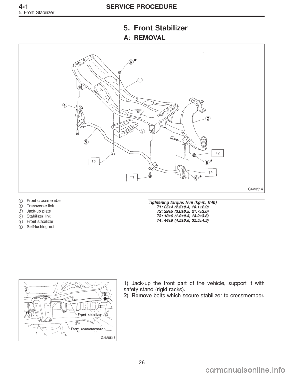
5. Front Stabilizer
A: REMOVAL
G4M0514
�1Front crossmember
�
2Transverse link
�
3Jack-up plate
�
4Stabilizer link
�
5Front stabilizer
�
6Self-locking nut
Tightening torque: N⋅m (kg-m, ft-lb)
T1: 25±4 (2.5±0.4, 18.1±2.9)
T2: 29±5 (3.0±0.5, 21.7±3.6)
T3: 18±5 (1.8±0.5, 13.0±3.6)
T4: 44±6 (4.5±0.6, 32.5±4.3)
G4M0515
1) Jack-up the front part of the vehicle, support it with
safety stand (rigid racks).
2) Remove bolts which secure stabilizer to crossmember.
26
4-1SERVICE PROCEDURE
5. Front Stabilizer
Page 1106 of 3342
 Remove bolts which secure stabilizer link to front trans-
verse link.
4) Remove jack-up plate from lower part of crossmember.
B: INSPECTION
1) Check bushing for cracks, fatigue or damage.
2")
G4M0516
3) Remove bolts which secure stabilizer link to front trans-
verse link.
4) Remove jack-up plate from lower part of crossmember.
B: INSPECTION
1) Check bushing for cracks, fatigue or damage.
2) Check stabilizer link for deformities, cracks, or damage,
and bushing for protrusions from the hole of stabilizer link
and its play.
G4M0519
C: INSTALLATION
1) To install, reverse the removal procedure.
NOTE:
�Install bushing (on front crossmember side) while align-
ing it with paint mark on stabilizer.
�Ensure that bushing and stabilizer have the same iden-
tification colors when installing.
2) Always tighten rubber bushing location when wheels
are in full contact with the ground and vehicle is at curb
weight condition.
Tightening torque:
Jack-up plate to crossmember:
18±5 N⋅m (1.8±0.5 kg-m, 13.0±3.6 ft-lb)
Stabilizer link to front transverse link:
29±5 N⋅m (3.0±0.5 kg-m, 21.7±3.6 ft-lb)
Stabilizer to crossmember:
25±4 N⋅m (2.5±0.4 kg-m, 18.1±2.9 ft-lb)
27
4-1SERVICE PROCEDURE
5. Front Stabilizer
Page 1107 of 3342
 Disconnect ground cable from battery.
2) Loosen front wheel nuts.
3) Lift-up vehicle, and remove front tires and wheels.
4) Remove both stabilizer and jack-u")
G4M0520
6. Front Crossmember
A: REMOVAL
1) Disconnect ground cable from battery.
2) Loosen front wheel nuts.
3) Lift-up vehicle, and remove front tires and wheels.
4) Remove both stabilizer and jack-up plate.
5) Disconnect tie-rod end from housing.
6) Remove front exhaust pipe.
G4M0521
7) Remove front transverse link from front crossmember
and body.
8) Remove nuts attaching engine mount cushion rubber to
crossmember.
9) Remove self-locking nuts connecting steering U/J and
pinion shaft.
10) Lift engine by approx. 10 mm (0.39 in) by using chain
block.
11) Support crossmember with a jack, remove nuts secur-
ing crossmember to body and lower crossmember gradu-
ally along with steering gearbox.
CAUTION:
When removing crossmember downward, be careful
that tie-rod end does not interfere with DOJ boot.
B: INSTALLATION
1) Installation is in the reverse order of removal proce-
dures.
CAUTION:
Always tighten rubber bushing when wheels are in full
contact with the ground and vehicle is at curb weight
condition.
Tightening torque:
Transverse link bushing to crossmember:
98±15 N⋅m (10.0±1.5 kg-m, 72±11 ft-lb)
Stabilizer to bushing:
25±4 N⋅m (2.5±0.4 kg-m, 18.1±2.9 ft-lb)
Tie-rod end to housing:
27.0±2.5 N⋅m (2.75±0.25 kg-m, 19.9±1.8 ft-lb)
Front cushion rubber to crossmember:
69±15 N⋅m (7.0±1.5 kg-m, 51±11 ft-lb)
Universal joint to pinion shaft:
24±3 N⋅m (2.4±0.3 kg-m, 17.4±2.2 ft-lb)
Crossmember to body:
98±15 N⋅m (10.0±1.5 kg-m, 72±11 ft-lb)
2) Purge air from power steering system.
NOTE:
Check wheel alignment and adjust if necessary.
28
4-1SERVICE PROCEDURE
6. Front Crossmember
Page 1108 of 3342
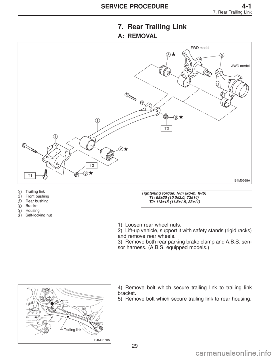
7. Rear Trailing Link
A: REMOVAL
B4M0569A
�1Trailing link
�
2Front bushing
�
3Rear bushing
�
4Bracket
�
5Housing
�
6Self-locking nut
Tightening torque: N⋅m (kg-m, ft-lb)
T1: 98±20 (10.0±2.0, 72±14)
T2: 113±15 (11.5±1.5, 83±11)
1) Loosen rear wheel nuts.
2) Lift-up vehicle, support it with safety stands (rigid racks)
and remove rear wheels.
3) Remove both rear parking brake clamp and A.B.S. sen-
sor harness. (A.B.S. equipped models.)
B4M0570A
4) Remove bolt which secure trailing link to trailing link
bracket.
5) Remove bolt which secure trailing link to rear housing.
29
4-1SERVICE PROCEDURE
7. Rear Trailing Link
Page 1109 of 3342
G4M0524
B: DISASSEMBLY
1. FRONT BUSHING
Using ST, press front bushing out of place.
ST 927720000 INSTALLER & REMOVER SET
G4M0525
2. REAR BUSHING
1) Remove housing. Refer to“4-2 WHEELS AND AXLES”
for removal procedures.
2) Using ST, press rear bushing out of place.
ST 927730000 INSTALLER & REMOVER SET
C: INSPECTION
Check trailing links for bends, corrosion or damage.
30
4-1SERVICE PROCEDURE
7. Rear Trailing Link
Page 1110 of 3342
D: ASSEMBLY
To assemble, reverse above disassembly procedures.
B4M0226A
1. FRONT BUSHING
Using ST, press bushing into trailing link.
ST 927720000 INSTALLER & REMOVER SET
CAUTION:
When installing bushing, turn ST plunger upside down
and press it until plunger end surface contacts trailing
link end surface.
G4M0924
CAUTION:
Install front bushing in the proper direction, as shown
in figure.
31
4-1SERVICE PROCEDURE
7. Rear Trailing Link
Page 1111 of 3342
B4M0224A
2. REAR BUSHING
1) Using ST, press bushing into trailing link.
ST 927730000 INSTALLER & REMOVER SET
NOTE:
If it is difficult to press bushing into trailing link, apply water-
diluted TIRE LUBE to the inner surface of ST as a lubricant.
Specified lubricant:
TIRE LUBE : water=1:3
B4M0195A
2) Press ST plunger until bushing flange protrudes beyond
trailing link.
ST 927730000 INSTALLER & REMOVER SET
32
4-1SERVICE PROCEDURE
7. Rear Trailing Link
 Remove housing. Refer to“4-2 WHEELS AND AXLES”
f")

 Using ST, press bushing into trailing link.
ST 927730000 INSTALLER & REMOVER SET
NOTE:
If it is difficult to press bushing into trailing link, apply water-
diluted TIRE LUB")