Page 3174 of 3342
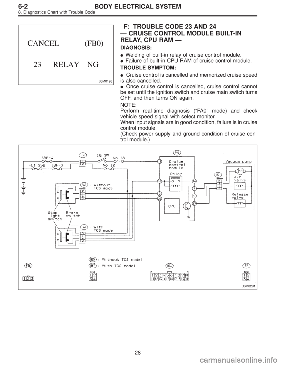
B6M0198
F: TROUBLE CODE 23 AND 24
—CRUISE CONTROL MODULE BUILT-IN
RELAY, CPU RAM—
DIAGNOSIS:
�Welding of built-in relay of cruise control module.
�Failure of built-in CPU RAM of cruise control module.
TROUBLE SYMPTOM:
�Cruise control is cancelled and memorized cruise speed
is also cancelled.
�Once cruise control is cancelled, cruise control cannot
be set until the ignition switch and cruise main switch turns
OFF, and then turns ON again.
NOTE:
Perform real-time diagnosis (“FA 0”mode) and check
vehicle speed signal with select monitor.
When input signals are in good condition, failure is in cruise
control module.
(Check power supply and ground condition of cruise con-
trol module.)
B6M0291
28
6-2BODY ELECTRICAL SYSTEM
8. Diagnostics Chart with Trouble Code
Page 3178 of 3342
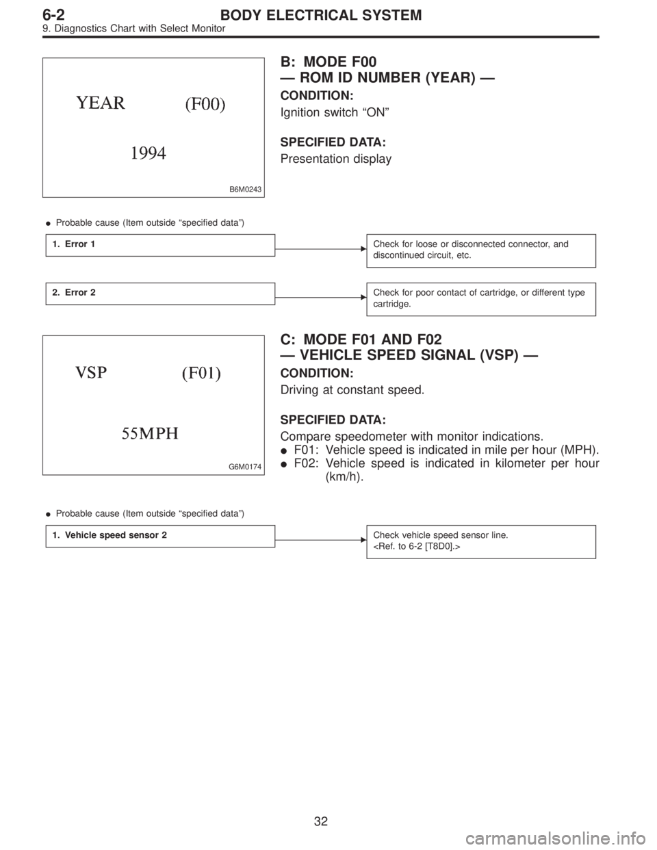
B6M0243
B: MODE F00
—ROM ID NUMBER (YEAR)—
CONDITION:
Ignition switch“ON”
SPECIFIED DATA:
Presentation display
�Probable cause (Item outside“specified data”)
1. Error 1
�Check for loose or disconnected connector, and
discontinued circuit, etc.
2. Error 2�Check for poor contact of cartridge, or different type
cartridge.
G6M0174
C: MODE F01 AND F02
—VEHICLE SPEED SIGNAL (VSP)—
CONDITION:
Driving at constant speed.
SPECIFIED DATA:
Compare speedometer with monitor indications.
�F01: Vehicle speed is indicated in mile per hour (MPH).
�F02: Vehicle speed is indicated in kilometer per hour
(km/h).
�Probable cause (Item outside“specified data”)
1. Vehicle speed sensor 2
�Check vehicle speed sensor line.
32
6-2BODY ELECTRICAL SYSTEM
9. Diagnostics Chart with Select Monitor
Page 3190 of 3342
 When working under a vehicle which is jacked-up,
always be sure to use safety stands.
2) The parking brake m")
3. Working Precautions
1. PRECAUTIONS WHEN WORKING WITH THE
PARTS MOUNTED ON THE VEHICLE
1) When working under a vehicle which is jacked-up,
always be sure to use safety stands.
2) The parking brake must always be applied during work-
ing. Also, in automatic transmission vehicles, keep the
select lever set to the P (Parking) range.
3) Be sure the workshop is properly ventilated when run-
ning the engine. Further, be careful not to touch the belt or
fan while the engine is operating.
4) Be careful not to touch hot metal parts, especially the
radiator and exhaust system immediately after the engine
has been shut off.
2. PRECAUTIONS IN TROUBLE DIAGNOSIS AND
REPAIR OF ELECTRIC PARTS
1) The battery cable must be disconnected from the bat-
tery’s (�) terminal, and the ignition switch must be set to the
OFF position, unless otherwise required by the diagnos-
tics.
2) Securely fasten the wiring harness with clamps and
slips so that the harness does not interfere with the body
end parts or edges and bolts or screws.
3) When installing parts, be careful not to catch them on
the wiring harness.
G6M0212
4) When disconnecting a connector, do not pull the wires,
but pull while holding the connector body.
11
6-3WIRING DIAGRAM
3. Working Precautions
Page 3196 of 3342
ABBREVIATION LIST
Abbr. Full name
A.B.S. Antilock Brake System
ACC Accessory
A/C Air Conditioning
AD Auto Down
AT Automatic Transmission
AU Auto Up
+B Battery
DN Down
DRL Daytime Running Light
E Ground
F/B Fuse & Joint Box
FL1.5 Fusible link 1.5 mm
2
IG Ignition
Illumi. Illumination
Abbr. Full name
LH Left Hand
Lo Low
M Motor
M/B Main Fuse Box
MG Magnet
Mi Middle
OP Optional Parts
PASS Passing
RH Right Hand
SBF Slow Blow Fuse
S.M.J. Super Multiple Junction
ST Starter
SW Switch
T.C.S. Traction Control System
UP Up
WASH Washer
17
6-3WIRING DIAGRAM
5. How to Use Super Multiple Junction (S.M.J.)
Page 3199 of 3342

MB-2 Power window circuit breaker
MB-3Engine control module
Fuel pump relay
Main relay
OBD-II service connector
MB-4 A/C relay holder
MB-5 He")
No. Load
MB-1Fuse holder (Rear power supply & seat
heater)
MB-2 Power window circuit breaker
MB-3Engine control module
Fuel pump relay
Main relay
OBD-II service connector
MB-4 A/C relay holder
MB-5 Headlight alarm relay (with security)
MB-6 Headlight LH
MB-7Daytime running light control module
Diode (Lighting)
Diode (Security)
Lighting switch
MB-8Combination meter
Front fog light switch
Headlight RH
Front fog light relay
MB-9Door lock timer
Headlight alarm relay
Interrupt relay
Radio
Security control module
Security indicator light
Spot light
Room light
Step light
Combination meter
Luggage room light
Trailer connector
Trunk room light
MB-10 A/C relay holder
SBF-6ABS relay box
TCS motor relay
SBF-7 TCS valve relay
ALT-1Combination meter
Daytime running light control module
Diode (TCS)
IG Headlight alarm relay
STCruise control module
Engine control module
Inhibitor switch (AT)
Interrupt relay
Starter interlock relay (MT)
FB-1Front washer motor
Rear washer motor
FB-2Engine control module
Main fan relay 1
FB-3Sub fan relay 2
Sub fan motor
FB-4Engine control module
Fuel pump relay
Ignition coil
Transmission control moduleNo. Load
FB-5 ABS relay box
FB-6Side marker light LH
Side marker light RH
FB-7 Door lock timer
FB-9 Hazard switch
FB-10AT shift lock control module
Key warning switch
Power antenna
FB-11 Radio
FB-12 Front accessory power supply
FB-13Mirror heater
Rear power supply relay
Remote control rearview mirror switch
Security control module
Vanity mirror illumination light
FB-14AT shift lock control module
Combination switch
Front wiper motor
Rear wiper motor
Rear wiper relay
FB-15ABS/TCS control module
Transmission control module
FB-16Rear defogger
Rear defogger condenser
Rear defogger switch
FB-17 Rear defogger switch
FB-18AT shift lock control module
Back-up light switch (MT)
Inhibitor switch (AT)
FB-19 Hazard switch
FB-20A/C switch
Combination meter
Mode control panel
TCS off switch
FB-22Blower motor relay
Check connector
Daytime running light control module
Daytime running light relay
FRESH/RECIRC actuator
Hi-beam relay
Power window and sunroof relay
Seat belt timer
FB-23 Airbag control module
FB-24 Airbag control module
FB-25 Lighting switch
20
6-3WIRING DIAGRAM
6. Wiring Diagram
Page 3203 of 3342

Lighting switch
MB")
No. Load
MB-2 Power window circuit breaker
MB-3Engine control module
Fuel pump relay
Main relay
OBD-II service connector
MB-4 A/C relay holder
MB-6 Headlight LH
MB-7Diode (Lighting)
Lighting switch
MB-8Combination meter
Headlight RH
MB-9Combination meter
Door lock timer
Luggage room light
Radio
Room light
MB-10 A/C relay holder
ALT-1 Combination meter
IG A/C relay holder
STCruise control module
Engine control module
Inhibitor switch
FB-2Engine control module
Main fan relay 1
FB-3Sub fan motor
Sub fan relay-2
FB-4Engine control module
Fuel pump relay
Ignition coil
Transmission control module
FB-6Side marker light LH
Side marker light RH
FB-7 Door lock timer
FB-9 Hazard switch
FB-10AT shift lock control module
Key warning switch
Power antenna
FB-11 Radio
FB-12 Cigarette lighter
FB-13 Remote control rearview mirror switch
FB-14AT shift lock control module
Combination switch
Front washer motor
Front wiper motor
Rear washer motor
Rear wiper motor
Rear wiper relayNo. Load
FB-15 Transmission control module
FB-16Rear defogger
Rear defogger condenser
Rear defogger switch
FB-17 Rear defogger switch
FB-18AT shift lock control module
Inhibitor switch
FB-19 Hazard switch
FB-20Combination meter
Mode control panel
FB-22Blower motor relay
Check connector
FRESH/RECIRC actuator
Mode actuator
Power window relay
Seat belt timer
FB-23 Airbag control module
FB-24 Airbag control module
FB-25 Lighting switch
FB-26 Parking switch
FB-27 Parking switch
FB-28 Illumination light
FB-29 Illumination light
FB-30Stop light switch
Stop & brake switch
FB-31 Horn relay
FB-32 Blower motor relay
FB-33 Parking switch
FB-34License plate light LH
License plate light RH
Rear combination light LH
Rear combination light RH
Rear finisher light LH
Rear finisher light RH
FB-35Cruise control main switch
Cruise control module
FB-38 Main fan relay 1
24
6-3WIRING DIAGRAM
6. Wiring Diagram
Page 3289 of 3342
![SUBARU LEGACY 1997 Service Repair Manual 7. Electrical Unit Location
Electrical unit Refer to;
A.B.S. control module 4-4a [T300]
A.B.S. G sensor (MT) 4-4a [T300]
A/C compressor relay�
7
A/C fuse�11
A/C main fan relay 1�10
A/C main fan relay](/manual-img/17/57434/w960_57434-3288.png "SUBARU LEGACY 1997 Service Repair Manual 7. Electrical Unit Location
Electrical unit Refer to;
A.B.S. control module 4-4a [T300]
A.B.S. G sensor (MT) 4-4a [T300]
A/C compressor relay�
7
A/C fuse�11
A/C main fan relay 1�10
A/C main fan relay")
7. Electrical Unit Location
Electrical unit Refer to;
A.B.S. control module 4-4a [T300]
A.B.S. G sensor (MT) 4-4a [T300]
A/C compressor relay�
7
A/C fuse�11
A/C main fan relay 1�10
A/C main fan relay 2�8
A/C pressure switch�2
A/C sub fan relay 2�9
ATF temperature sensor 2-7 [T2B1]
Blower motor resistor�
26
Blower relay�13
Camshaft position sensor 2-7 [T2A2]
Check connector�
25
Clutch switch (MT) 6-2 [T300]
Crankshaft position sensor 2-7 [T2A2]
Cruise control module 6-2 [T300]
Cruise control pump 6-2 [T300]
Data link connector (for OBD-II G.S.T.) 2-7 [T2A1]
Data link connector (for S.S.M.) 2-7 [T2A1]
Diagnosis connector 4-4a [T300]
Diagnosis terminal (Ground) 4-4a [T300]
Door lock timer�
27
Engine control module 2-7 [T2A1]
Engine coolant temperature sensor 2-7 [T2A2]
Engine hood switch (Security) 6-2 [K6A0]
Evaporator thermoswitch�
29
F/B�15
FRESH/RECIRC actuator�28
Fuel pump relay 2-7 [T2A3]
Fuel gauge module�
31
Fuel gauge sub module (AWD)�32
FWD switch (AT)�1
Headlight alarm relay (Security) 6-2 [K6A0]
Headlight relay LH�
5
Headlight relay RH�6
Horn relay�14
Electrical unit Refer to;
Hydraulic unit (A.B.S.) 4-4a [T300]
Ignition coil 2-7 [T2A3]
Ignitor 2-7 [T2A3]
Idle air control solenoid valve 2-7 [T2A3]
Illumination control module�
21
Inhibitor switch 6-2 [T300]
Knock sensor 2-7 [T2A2]
Main fan relay�
19
Main relay 2-7 [T2A3]
Mass air flow sensor 2-7 [T2A2]
Mode actuator�
12
M/B�4
Oil pressure switch�3
Oxygen sensor 2-7 [T2A2]
Pedal stroke sensor (T.C.S.) 4-4b [T300]
Power window and sunroof relay�
24
Power window circuit breaker�23
Purge control solenoid valve 2-7 [T2A3]
Rear defogger relay�
17
Seat belt timer�20
Security control module 6-2 [K6A0]
Shift lock control module�
22
Starter interrupt relay (Security) 6-2 [K6A0]
Stop & brake switch (With cruise con-
trol)6-2 [T300]
Sunroof control module�
30
Tail and illumination relay�18
T.C.S. control module 4-4b [T300]
T.C.S. motor relay 4-4b [T300]
T.C.S. valve relay 4-4b [T300]
Throttle position sensor 2-7 [T2A2]
Test mode connector 2-7 [T2A1]
Transmission control module 2-7 [T2B1]
Turn & hazard module�
16
Vehicle speed sensor 1 2-7 [T2B1]
Vehicle speed sensor 2 2-7 [T2B1]
11 0
6-3WIRING DIAGRAM
7. Electrical Unit Location
Page 3305 of 3342

Connector Connecting to
No. Pole Color Area No. Name
E1 6 * A-3 B20
Bulkhead wiring harness E2 12 Gray A-3 B21
E3 16 Gray A-3 B22
E4 2 Blue A-2 Purge control solenoid valve
E5 2 Light gray A-2 Injector #1
E6 2 Dark gray A-3 Injector #3
E7 3 Gray A-3 Idle air control solenoid valve
E8 2 Brown B-3 Engine coolant temperature sensor
E9 1 * B-3 Thermometer
E10 2 Gray B-3 Crankshaft position sensor
E11 1 * B-3 Oil pressure switch
E12 3 Gray A-3 Ignition coil
E13 3 Brown A-3 Throttle position sensor
E14 2 Gray B-3 Knock sensor
E15 2 Dark gray B-4 Camshaft position sensor
E16 2 Light gray B-4 Injector #2
E17 2 Dark gray B-4 Injector #4
E18 2 Brown B-3 EGR solenoid (AT)
*: Non-colored
Connector Connecting to
No. Pole Color Area No. Name
T1 2 Gray C-1 B24
Bulkhead wiring harness (MT)
T2 2 Brown C-1 B25
T3 12 Gray D-3 B12
Bulkhead wiring harness (AT)
T4 16 Gray D-3 B11
T5 4 Gray C-1/C-3 B19 Bulkhead wiring harness
T6 4 Gray D-2/D-4 Rear oxygen sensor
T7 12 * C-4 Inhibitor switch (AT)
*: Non-colored
126
6-3WIRING DIAGRAM
8. Electrical Wiring Harness and Ground Point