Page 3139 of 3342

O: AIRBAG WARNING LIGHT REMAINS OFF.
DIAGNOSIS:
�Fuse No. 15 is blown.
�Body harness circuit is open.
�Airbag warning light is faulty.
�Airbag main harness is faulty.
�Airbag control module is faulty.
1. Fuse No. 15 inspection
2. Body harness inspection
3. Airbag warning light module (in combination
meter) inspection
4. Airbag main harness inspection
CAUTION:
Before performing diagnostics on airbag system, turn
ignition switch“OFF”, disconnect battery ground
terminal, and then wait at least 20 seconds.
G5M0460
1. FUSE No. 15 INSPECTION
Remove and visually check fuse No. 15.
: Is fuse No. 15 blown?
: Replace fuse No. 15.
If fuse No. 15 blows again, go to step2.
: Go to step2.
2. BODY HARNESS INSPECTION
Turn ignition switch“ON”(engine off) to make sure other
warning lights (in combination meter) illuminate.
: Do all the warning lights (in combination
meter) except airbag warning light come
on?
: Go to step3.
: Repair body harness.
�
�
�
36
5-5bSUPPLEMENTAL RESTRAINT SYSTEM (ELECTRIC SENSOR TYPE)
5. Diagnostics Chart with Trouble Code
Page 3140 of 3342
 INSPECTION
1) Turn ignition switch“OFF”, disconnect battery ground
cable and then wait at least 20 seconds.
2) Disconnect body harnes")
B5M0122B
3. AIRBAG WARNING LIGHT MODULE (IN
COMBINATION METER) INSPECTION
1) Turn ignition switch“OFF”, disconnect battery ground
cable and then wait at least 20 seconds.
2) Disconnect body harness connector (B31) from connec-
tor (AB1).
B5M0124A
3) Connect battery ground cable and turn ignition switch
“ON”(engine off) to make sure airbag warning light illumi-
nates.
: Does the airbag warning light come on?
: Go to step4.
: Replace airbag warning light module�1.
G5M0312
4. AIRBAG MAIN HARNESS INSPECTION
1) Turn ignition switch“OFF”, disconnect battery ground
cable and then wait at least 20 seconds.
2) Connect body harness connector (B31) and connector
(AB1).
3) Disconnect connectors (AB3) and (AB8) below steering
column.
G5M0313
4) Disconnect connector (AB6) from airbag control mod-
ule.
5) Connect battery ground cable and turn ignition switch
“ON”to make sure airbag warning light illuminates.
: Does the airbag warning light come on?
: Replace airbag control module.
: Replace airbag main harness.
37
5-5bSUPPLEMENTAL RESTRAINT SYSTEM (ELECTRIC SENSOR TYPE)
5. Diagnostics Chart with Trouble Code
Page 3141 of 3342
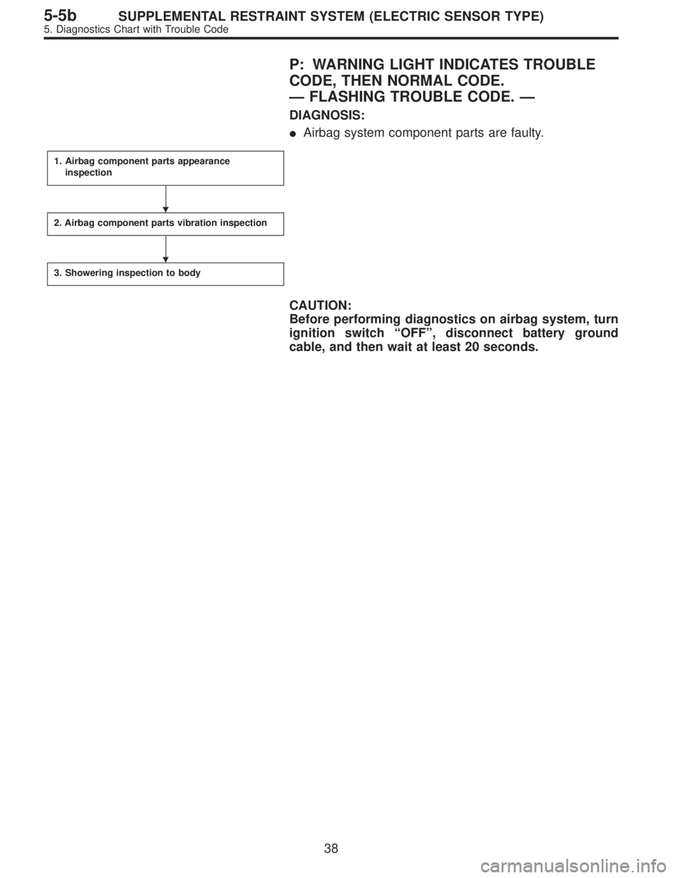
P: WARNING LIGHT INDICATES TROUBLE
CODE, THEN NORMAL CODE.
—FLASHING TROUBLE CODE.—
DIAGNOSIS:
�Airbag system component parts are faulty.
1. Airbag component parts appearance
inspection
2. Airbag component parts vibration inspection
3. Showering inspection to body
CAUTION:
Before performing diagnostics on airbag system, turn
ignition switch“OFF”, disconnect battery ground
cable, and then wait at least 20 seconds.
�
�
38
5-5bSUPPLEMENTAL RESTRAINT SYSTEM (ELECTRIC SENSOR TYPE)
5. Diagnostics Chart with Trouble Code
Page 3144 of 3342

Q: WARNING LIGHT INDICATES TROUBLE
CODE, THEN NORMAL CODE.
—FLASHING NORMAL CODE.—
DIAGNOSIS:
�Airbag connector is faulty.
�Fuse No. 16 is blown.
�Airbag main harness is faulty.
�Airbag control module is faulty.
�Body harness is faulty.
1. Airbag connector appearance inspection
2. Airbag connector vibration inspection
3. Showering inspection to body
4. Fuse No. 16, airbag main harness, airbag
control module, body harness appearance
inspection
5. Fuse No. 16, airbag main harness, body
harness vibration inspection
6. Showering inspection to body
7. Warning light illumination check
CAUTION:
Before performing diagnostics on airbag system, turn
ignition switch“OFF”, disconnect battery ground
cable, and then wait at least 20 seconds.
1. AIRBAG CONNECTOR APPEARANCE INSPECTION
Conduct appearance inspection on airbag connectors
(AB2) through (AB8).
: Is there anything unusual about the appear-
ance of connectors (AB2) through (AB8)?
: Replace faulty airbag component parts.
: Go to step2.
NOTE:
Check terminals, case and wiring harnesses for damage.
�
�
�
�
�
�
41
5-5bSUPPLEMENTAL RESTRAINT SYSTEM (ELECTRIC SENSOR TYPE)
5. Diagnostics Chart with Trouble Code
Page 3146 of 3342

5. FUSE No. 16, AIRBAG MAIN HARNESS, BODY
HARNESS VIBRATION INSPECTION
Conduct vibration inspection on fuse No. 16, airbag main
harness and body harness.
CAUTION:
Do not shake or vibrate airbag control module.
: Do fuse No. 16, airbag main harness or body
harness malfunction again when shaking?
: Replace faulty airbag component parts.
: Go to step6.
NOTE:
Gently shake each part.
G5M0461
6. SHOWERING INSPECTION TO BODY
Spray water on vehicle body.
CAUTION:
Do not directly spray water on each part.
: Does water leak into the passenger com-
partment when showering vehicle?
: Replace faulty airbag component parts.
: Go to step7.
NOTE:
If leaks are noted, check wiring harnesses as water may
leak along them and get parts wet.
7. WARNING LIGHT ILLUMINATION CHECK
Turn ignition switch“ON”(engine off) and observe airbag
warning light.
: Does the airbag warning light comes on for
about 7 seconds, then go out and stay out?
: Clear memory.
:Goto“DIAGNOSTICS PROCEDURE”.
43
5-5bSUPPLEMENTAL RESTRAINT SYSTEM (ELECTRIC SENSOR TYPE)
5. Diagnostics Chart with Trouble Code
Page 3153 of 3342

Main power supply 2�Battery voltage is present when main power is tu")
5. Control Module I/O Signal
G6M0015
ContentTerminal
No.Measuring conditions and I/O signals (ignition switch ON and engine idling)
Main power supply 2�Battery voltage is present when main power is turned ON.
�“0”volt is present when main power is turned OFF.
Inhibitor switch (AT) (U.S.A.)
N position switch (AT) (CANADA)4�“0”volt is present when selector lever is set to P or N position (CANADA: N position only).
�Battery voltage is present when selector lever is other than P or N position (CANADA: N
position only).
Air valve 5�“0”volt is present when vehicle is stopped.
�ON-and-OFF (“0”-and-battery voltage) operation is alternately repeated while cruise control
is operating.
GND 6—
Vacuum pump motor 7�“0”volt is present when vehicle is stopped.
�ON-and-OFF (“0”-and-battery voltage) operation is alternately repeated while cruise control
is operating.
Data link connector 8—
RESUME/ACCEL switch 9�Battery voltage is present when switch is turned ON.
�“0”volt is present when switch is turned OFF.
SET/COAST switch 10�Battery voltage is present when switch is turned ON.
�“0”volt is present when switch is turned OFF.
Ignition switch 12�Battery voltage is present when ignition switch is turned ON.
�“0”volt is present when ignition switch is turned OFF.
Release valve 13�“0”volt is present when vehicle is stopped.
�ON-and-OFF (“0”-and-battery voltage) operation is alternately repeated while cruise control
is operating.
Power supply to vacuum pump
motor, air valve, release valve14�“0”volt is present when vehicle is stopped.
�Battery voltage is present while cruise control is operating.
Cruise main switch 15�Battery voltage is present during pressing the main switch, and then approx. 12 V is
present while switch is turned ON.
�“0”volt is present when switch is turned OFF.
Brake switch 16Turn the cruise main switch to ON and leave clutch pedal released (MT).
Then check that;
�“0”volt is present when brake pedal is depressed.
�Battery voltage is present when brake pedal is released.
Additionally only in MT vehicle, keep the cruise main switch to ON and leave brake pedal
released.
Then check that;
�“0”volt is present when clutch pedal is depressed.
�Battery voltage is present when clutch pedal is released.
Data link connector 17—
Data link connector 18—
Vehicle speed sensor 2 19Lift-up the vehicle until all four wheels are raised off ground, and then rotate any wheel manu-
ally.
Approx. 5 and 0 volt pulse signals are alternately input to cruise control module.
Stop light switch 20Turn ignition switch to OFF.
Then check that;
�Battery voltage is present when brake pedal is depressed.
�“0”volt is present when brake pedal is released.
NOTE:
Voltage at terminals 5, 7, 13 and 14 cannot be checked unless vehicle is driving by cruise control operation.
7
6-2BODY ELECTRICAL SYSTEM
5. Control Module I/O Signal
Page 3155 of 3342

B: ON-BOARD DIAGNOSIS WITH SELECT
MONITOR
1. GENERAL
The on-board diagnosis function of the cruise control sys-
tem uses an external select monitor.
The on-board diagnosis function operates in two
categories, which are used depending on the type of prob-
lems;
�Cruise cancel conditions diagnosis
�Real-time diagnosis
Applicable cartridge No.: 498349601
�Cruise cancel conditions diagnosis
This category of diagnosis requires actual vehicle driv-
ing in order to determine the cause, (as when cruise
speed is cancelled during driving although cruise cancel
condition is not entered).
Cruise control module memory stores the cancel condi-
tion (Code No.) which occurred during driving. When
there are plural cancel conditions (Code No.), they are
shown in order, for 2 seconds per Code No., on the
select monitor.
CAUTION:
�The cruise control memory stores not only the
cruise“cancel”which occurred (although“cancel”
operation is not entered by the driver), but also the
“cancel”condition input by the driver.
�The content of memory is cleared when ignition
switch or cruise main switch is turned OFF.
�Real-time diagnosis
The real-time diagnosis function is used to determine
whether or not the input of output signal system is in good
order, according to signal emitted from switches, sensors,
etc.
Vehicle cannot be driven at cruise speed because prob-
lems occurs in the cruise control system or its associ-
ated circuits.
Monitor the signal conditions from switches and sen-
sors.
9
6-2BODY ELECTRICAL SYSTEM
6. Diagnostics Chart for On-board Diagnosis System
Page 3156 of 3342
 Connect select monitor.
2) Start the engine and turn cruise control main switch to
ON.
3) Set select monitor in“FB0”mode.
4) Drive vehicle at least 40 km/h")
2. CRUISE CANCEL CONDITIONS DIAGNOSIS
1) Connect select monitor.
2) Start the engine and turn cruise control main switch to
ON.
3) Set select monitor in“FB0”mode.
4) Drive vehicle at least 40 km/h (25 MPH) with cruise
speed set.
5) If cruise speed is canceled itself (without doing any
cancel operations), a trouble code will appear on select
monitor display.
CAUTION:
�A trouble code will also appear when cruise cancel
is effected by driver. Do not confuse.
�Have a co-worker ride in vehicle to assist in diagno-
sis during driving.
NOTE:
Trouble code will be cleared by turning ignition switch or
cruise control main switch to OFF.
3. REAL-TIME DIAGNOSIS
1) Connect select monitor.
2) Turn ignition switch and cruise control main switch to
ON.
3) Set select monitor in“FA 0”mode.
4) Ensure that normal indication is displayed when con-
trols are operated as indicated below:
�When SET/COAST switch is pressed.
�When RESUME/ACCEL switch is pressed.
�When brake pedal is depressed. (Stop and brake switch
turns ON.)
�When clutch pedal is depressed. (MT model)
�When select lever is set to N position. (AT model)
10
6-2BODY ELECTRICAL SYSTEM
6. Diagnostics Chart for On-board Diagnosis System