Page 290 of 3342
B: DISASSEMBLY
B2M1264A
1) Remove bolts which secure rocker shaft.
2) Extract rocker shaft. Remove valve rocker arms,
springs and shaft supports from rocker shaft.
CAUTION:
Arrange all removed parts in order so that they can be
installed in their original positions.
3) Loosen rocker nut, and then remove rocker screw and
nut from rocker arm.
CAUTION:
Do not remove rocker screw and nut unless necessary.
28
2-3SERVICE PROCEDURE
4. Valve Rocker Assembly
Page 291 of 3342
G2M0131
C: INSPECTION
1. HYDRAULIC LASH ADJUSTER
1) Bleed air from hydraulic lash adjuster as described
below:
(1) While dipping hydraulic lash adjuster in engine oil,
as shown in Figure, push check ball in usinga2mm
(0.08 in) diameter round bar.
(2) With check ball pushed in, manually move plunger
up and down at one second intervals until air bubbles
disappear.
(3) After air bubbles disappear, remove round bar and
quickly push plunger in to ensure it is locked. If plunger
does not lock properly, replace hydraulic lash adjuster.
CAUTION:
Leave hydraulic lash adjuster (after air is bled) in
engine oil until it is ready for installation.
2) Replace hydraulic lash adjuster with a new one if valve
contact surface is scratched.
29
2-3SERVICE PROCEDURE
4. Valve Rocker Assembly
Page 295 of 3342
5. Camshaft
A: REMOVAL
1. RELATED PARTS
1) Remove timing belt, camshaft sprockets and related
parts.
2) Remove valve rocker assembly.
2. CAMSHAFT LH
B2M0384A
1) Remove oil level gauge guide attaching bolt.
2) Remove camshaft support LH.
CAUTION:
Do not damage the camshaft position sensor.
3) Remove O-ring.
4) Remove camshaft LH.
5) Remove oil seal.
CAUTION:
�Do not remove oil seal unless necessary.
�Do not scratch journal surface when removing oil
seal.
33
2-3SERVICE PROCEDURE
5. Camshaft
Page 296 of 3342
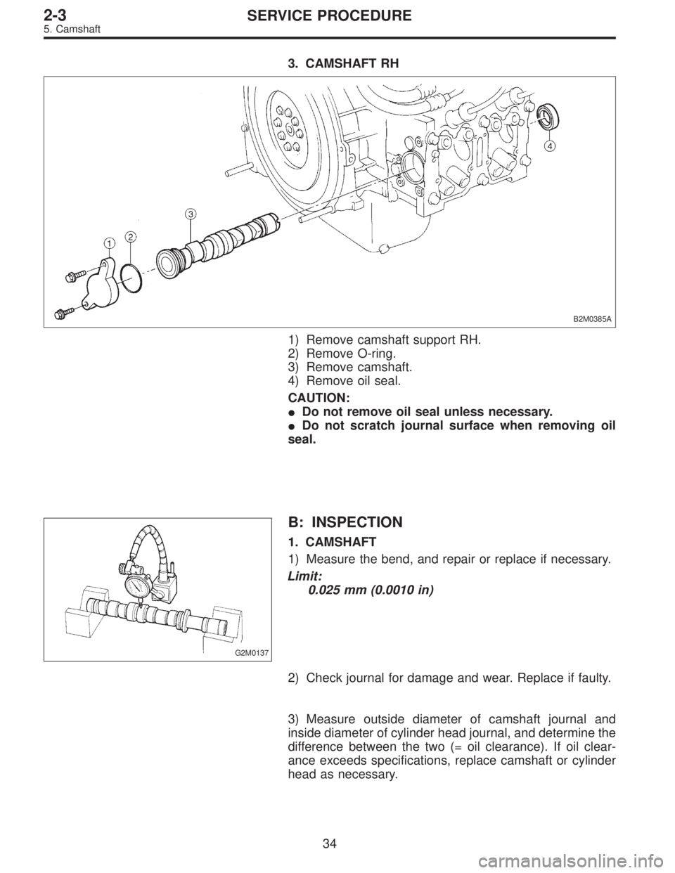
3. CAMSHAFT RH
B2M0385A
1) Remove camshaft support RH.
2) Remove O-ring.
3) Remove camshaft.
4) Remove oil seal.
CAUTION:
�Do not remove oil seal unless necessary.
�Do not scratch journal surface when removing oil
seal.
G2M0137
B: INSPECTION
1. CAMSHAFT
1) Measure the bend, and repair or replace if necessary.
Limit:
0.025 mm (0.0010 in)
2) Check journal for damage and wear. Replace if faulty.
3) Measure outside diameter of camshaft journal and
inside diameter of cylinder head journal, and determine the
difference between the two (= oil clearance). If oil clear-
ance exceeds specifications, replace camshaft or cylinder
head as necessary.
34
2-3SERVICE PROCEDURE
5. Camshaft
Page 297 of 3342

ItemRight-hand camshaft Front Center Rear
Left-hand camshaft Rear Center Front
Clearance at journalStandard 0.055—0.090 (0.0022—0.0035)
Limit 0.10 (0.0039 )
Camshaft journal O.D.31.9")
Unit: mm (in)
ItemRight-hand camshaft Front Center Rear
Left-hand camshaft Rear Center Front
Clearance at journalStandard 0.055—0.090 (0.0022—0.0035)
Limit 0.10 (0.0039 )
Camshaft journal O.D.31.935—31.950
(1.2573—1.2579)37.435—37.450
(1.4738—1.4744)37.935—37.950
(1.4935—1.4941)
Journal hole I.D.32.005—32.025
(1.2600—1.2608)37.505—37.525
(1.4766—1.4774)38.005—38.025
(1.4963—1.4970)
B2M1209A
4) Check cam face condition; remove minor faults by
grinding with oil stone. Measure the cam height H; replace
if the limit has been exceeded.
Cam height: H
Standard
IN: 32.244—32.344 mm (1.2694—1.2734 in)
EX: 31.964—32.064 mm (1.2584—1.2624 in)
Limit
IN: 32.094 mm (1.2635 in)
EX: 31.814 mm (1.2525 in)
Cam base circle diameter A:
IN: 27.5 mm (1.083 in)
EX: 27.0 mm (1.063 in)
G2M0139
2. CAMSHAFT SUPPORT
Measure the thrust clearance of camshaft with dial gauge.
If the clearance exceeds the limit, replace camshaft sup-
port.
Standard:
0.030—0.260 mm (0.0012—0.0102 in)
Limit:
0.35 mm (0.0138 in)
35
2-3SERVICE PROCEDURE
5. Camshaft
Page 300 of 3342
3. RELATED PARTS
1) Install valve rocker assembly.
B2M0418B
Tightening torque: N⋅m (kg-m, ft-lb)
T1: 5±1 (0.5±0.1, 3.6±0.7)
T2: 12±1 (1.2±0.1, 8.7±0.7)
2) Install timing belt, camshaft sprockets and related parts.
6. Cylinder Head
A: REMOVAL
1. INTAKE MANIFOLD
1) Release fuel pressure.
2) Drain engine coolant.
3) Remove intake manifold.
4) Remove engine coolant pipe.
38
2-3SERVICE PROCEDURE
5. Camshaft - 6. Cylinder Head
Page 301 of 3342
3. RELATED PARTS
1) Install valve rocker assembly.
B2M0418B
Tightening torque: N⋅m (kg-m, ft-lb)
T1: 5±1 (0.5±0.1, 3.6±0.7)
T2: 12±1 (1.2±0.1, 8.7±0.7)
2) Install timing belt, camshaft sprockets and related parts.
6. Cylinder Head
A: REMOVAL
1. INTAKE MANIFOLD
1) Release fuel pressure.
2) Drain engine coolant.
3) Remove intake manifold.
4) Remove engine coolant pipe.
38
2-3SERVICE PROCEDURE
5. Camshaft - 6. Cylinder Head
Page 302 of 3342
2. CYLINDER HEAD
B2M0119A
1) Remove timing belt, camshaft sprocket and related
parts.
2) Remove oil level gauge guide attaching bolt (left hand
only) and oil level gauge guide.
B2M0120A
3) Remove cylinder head bolts in numerical sequence
shown in Figure.
CAUTION:
Leave bolts�
1and�3engaged by three or four threads
to prevent cylinder head from falling.
4) While tapping cylinder head with a plastic hammer,
separate it from cylinder block.
Remove bolts�
1and�3to remove cylinder head.
5) Remove cylinder head gasket.
CAUTION:
Do not scratch the mating surface of cylinder head and
cylinder block.
6) Similarly, remove right side cylinder head.
39
2-3SERVICE PROCEDURE
6. Cylinder Head
 Remove bolts which secure rocker shaft.
2) Extract rocker shaft. Remove valve rocker arms,
springs and shaft supports from rocker shaft.
CAUTION:
Arrange all removed parts i")
 Bleed air from hydraulic lash adjuster as described
below:
(1) While dipping hydraulic lash adjuster in engine oil,
as shown in Figure, push check b")
![SUBARU LEGACY 1997 Service Repair Manual 5. Camshaft
A: REMOVAL
1. RELATED PARTS
1) Remove timing belt, camshaft sprockets and related
parts.
<Ref. to 2-3 [W3A0].>
2) Remove valve rocker assembly.
<Ref. to 2-3 [W4A0].>
2. CAMSHAFT LH
B2M0384](/manual-img/17/57434/w960_57434-294.png "SUBARU LEGACY 1997 Service Repair Manual 5. Camshaft
A: REMOVAL
1. RELATED PARTS
1) Remove timing belt, camshaft sprockets and related
parts.
<Ref. to 2-3 [W3A0].>
2) Remove valve rocker assembly.
<Ref. to 2-3 [W4A0].>
2. CAMSHAFT LH
B2M0384")
![SUBARU LEGACY 1997 Service Repair Manual 3. RELATED PARTS
1) Install valve rocker assembly.
<Ref. to 2-3 [W4E0].>
B2M0418B
Tightening torque: N⋅m (kg-m, ft-lb)
T1: 5±1 (0.5±0.1, 3.6±0.7)
T2: 12±1 (1.2±0.1, 8.7±0.7)
2) Install timing](/manual-img/17/57434/w960_57434-299.png "SUBARU LEGACY 1997 Service Repair Manual 3. RELATED PARTS
1) Install valve rocker assembly.
<Ref. to 2-3 [W4E0].>
B2M0418B
Tightening torque: N⋅m (kg-m, ft-lb)
T1: 5±1 (0.5±0.1, 3.6±0.7)
T2: 12±1 (1.2±0.1, 8.7±0.7)
2) Install timing")
![SUBARU LEGACY 1997 Service Repair Manual 3. RELATED PARTS
1) Install valve rocker assembly.
<Ref. to 2-3 [W4E0].>
B2M0418B
Tightening torque: N⋅m (kg-m, ft-lb)
T1: 5±1 (0.5±0.1, 3.6±0.7)
T2: 12±1 (1.2±0.1, 8.7±0.7)
2) Install timing](/manual-img/17/57434/w960_57434-300.png "SUBARU LEGACY 1997 Service Repair Manual 3. RELATED PARTS
1) Install valve rocker assembly.
<Ref. to 2-3 [W4E0].>
B2M0418B
Tightening torque: N⋅m (kg-m, ft-lb)
T1: 5±1 (0.5±0.1, 3.6±0.7)
T2: 12±1 (1.2±0.1, 8.7±0.7)
2) Install timing")
![SUBARU LEGACY 1997 Service Repair Manual 2. CYLINDER HEAD
B2M0119A
1) Remove timing belt, camshaft sprocket and related
parts.
<Ref. to 2-3 [W3A0].>
2) Remove oil level gauge guide attaching bolt (left hand
only) and oil level gauge guide.
B](/manual-img/17/57434/w960_57434-301.png "SUBARU LEGACY 1997 Service Repair Manual 2. CYLINDER HEAD
B2M0119A
1) Remove timing belt, camshaft sprocket and related
parts.
<Ref. to 2-3 [W3A0].>
2) Remove oil level gauge guide attaching bolt (left hand
only) and oil level gauge guide.
B")