Page 275 of 3342
 Bleed air from hydraulic lash adjuster as described
below:
(1) While dipping hydraulic lash adjuster in engine oil,
as shown in Figure, push check ball in usinga2mm
(0.08 in) diameter round")
G2M0131
3) Bleed air from hydraulic lash adjuster as described
below:
(1) While dipping hydraulic lash adjuster in engine oil,
as shown in Figure, push check ball in usinga2mm
(0.08 in) diameter round bar.
(2) With check ball pushed in, manually move plunger
up and down at one second intervals until air bubbles
disappear.
(3) After air bubbles disappear, remove round bar and
quickly push plunger in to ensure it is locked. If plunger
does not lock properly, replace hydraulic lash adjuster.
CAUTION:
Leave hydraulic lash adjuster (after air is bled) in
engine oil until it is ready for installation.
G2M0200
4) Using ST;
(1) Insert lash adjuster into ST, and fill ST with engine
oil. Usinga2mm(0.08 in) diameter rod, push check
ball in.
ST 499597000 OIL SEAL GUIDE
(2) With check ball pushed in, push plunger at an inter-
val of one second.
(3) Move plunger up and down until air bubbles are no
longer emitted from lash adjuster.
NOTE:
Hold hydraulic lash adjusters vertically during air bleeding.
5) Remove the rod. Push plunger to ensure that air is
completely bled out.
CAUTION:
If plunger does not properly lock (when pushed),
replace lash adjuster with a new one.
13
2-3SERVICE PROCEDURE
2. Hydraulic Lash Adjuster
Page 277 of 3342
3. Timing Belt
A: REMOVAL
1. CRANKSHAFT PULLEY AND BELT COVER
G2M0107
G2M0108
1) Remove V-belt and A/C belt tensioner.
2) Remove pulley bolt. To lock crankshaft use ST.
ST 499977000 CRANKSHAFT PULLEY WRENCH
3) Remove crankshaft pulley.
4) Remove left side belt cover.
5) Remove right side belt cover.
6) Remove front belt cover.
15
2-3SERVICE PROCEDURE
3. Timing Belt
Page 279 of 3342
G2M0111
(2) Using white paint, put alignment and/or arrow
marks on timing belts in relation to the sprockets.
Z
1: 44 tooth length
Z
2: 40.5 tooth length
B2M0065
2) Loosen tensioner adjuster mounting bolts.
3) Remove belt idler.
4) Remove belt idler No. 2.
5) Remove timing belt.
6) Remove tensioner adjuster.
17
2-3SERVICE PROCEDURE
3. Timing Belt
Page 280 of 3342
3. BELT TENSIONER AND IDLER
G2M0112
1) Remove belt idler.
2) Remove belt tensioner and spacer.
3) Remove belt tensioner adjuster.
18
2-3SERVICE PROCEDURE
3. Timing Belt
Page 281 of 3342
4. SPROCKET
B2M0416A
G2M0114
1) Remove left side camshaft sprocket.
2) Remove right side camshaft sprocket. To lock camshaft
use ST.
ST 499207100 CAMSHAFT SPROCKET WRENCH
3) Remove crankshaft sprocket.
4) Remove left side belt cover No. 2.
5) Remove right side belt cover No. 2.
CAUTION:
Do not damage or lose the seal rubber when removing
belt covers.
6) Remove tensioner bracket.
19
2-3SERVICE PROCEDURE
3. Timing Belt
Page 282 of 3342
 Check timing belt teeth for breaks, cracks, and wear. If
any fault is found, replace belt.
2) Check the condition of back side of belt; if any crack is
found, replace b")
B: INSPECTION
1. TIMING BELT
1) Check timing belt teeth for breaks, cracks, and wear. If
any fault is found, replace belt.
2) Check the condition of back side of belt; if any crack is
found, replace belt.
CAUTION:
�Be careful not to let oil, grease or coolant contact
the belt. Remove quickly and thoroughly if this hap-
pens.
G2M0115
�Do not bend the belt sharply.
Bending radius: h
60 mm (2.36 in) or more
2. BELT TENSION ADJUSTER
1) Visually check oil seals for leaks, and rod ends for
abnormal wear or scratches. If necessary, replace belt ten-
sion adjuster.
CAUTION:
Slight traces of oil at rod’s oil seal does not indicate a
problem.
2) While holding tensioner with both hands, push the rod
section against floor or wall ensuring the rod section will
react as follows:
(1) When applying a force of 147 N (15 kg, 33 lb), the
rod section should not sink.
(2) When applying a force of 147 to 490 N (15 to 50 kg,
33 to 110 lb), the rod section should maintain a projec-
tionally acting force and should not sink within 8.5 sec-
onds.
20
2-3SERVICE PROCEDURE
3. Timing Belt
Page 287 of 3342
G2M0122
1) Installation of timing belt
(1) Using ST, turn left and right camshaft sprockets so
that their alignment marks come to top positions.
ST 499207100 CAMSHAFT SPROCKET WRENCH
B2M0417A
(2) While aligning alignment mark on timing belt with
marks on sprockets, position timing belt properly.
CAUTION:
Ensure belt’s rotating direction is correct.
2) Install belt idler No. 2.
3) Install belt idler.
B2M0111
4) Loosen belt tension adjuster attaching bolts and move
adjuster all the way to the left. Tighten the bolts.
G2M0125
5) After ensuring that the marks on timing belt and cam-
shaft sprockets are aligned, remove stopper pin from belt
tension adjuster.
CAUTION:
After properly installing timing belt, remove rocker
cover and ensure that the valve lash adjuster contains
no air.
25
2-3SERVICE PROCEDURE
3. Timing Belt
Page 289 of 3342
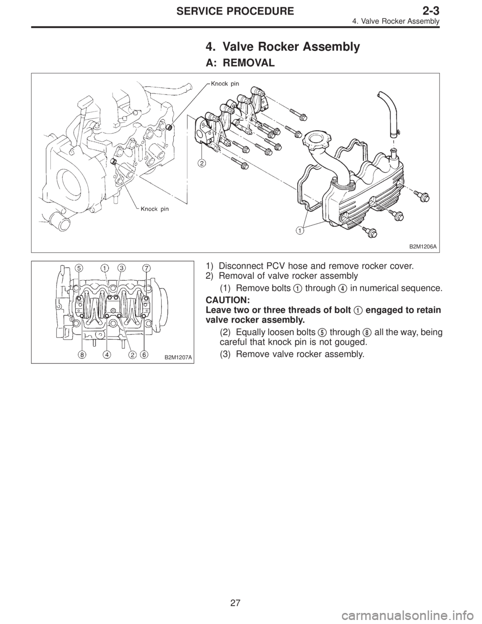
4. Valve Rocker Assembly
A: REMOVAL
B2M1206A
B2M1207A
1) Disconnect PCV hose and remove rocker cover.
2) Removal of valve rocker assembly
(1) Remove bolts�
1through�4in numerical sequence.
CAUTION:
Leave two or three threads of bolt�
1engaged to retain
valve rocker assembly.
(2) Equally loosen bolts�
5through�8all the way, being
careful that knock pin is not gouged.
(3) Remove valve rocker assembly.
27
2-3SERVICE PROCEDURE
4. Valve Rocker Assembly
 Remove V-belt and A/C belt tensioner.
2) Remove pulley bolt. To lock crankshaft use ST.
ST 499977000 CRANKSHAFT PULLEY")
 Using white paint, put alignment and/or arrow
marks on timing belts in relation to the sprockets.
Z
1: 44 tooth length
Z
2: 40.5 tooth length
B2M0065
2) Loosen tensioner adjuster mounting")
 Remove belt idler.
2) Remove belt tensioner and spacer.
3) Remove belt tensioner adjuster.
18
2-3SERVICE PROCEDURE
3. Timing Belt")
 Remove left side camshaft sprocket.
2) Remove right side camshaft sprocket. To lock camshaft
use ST.
ST 499207100 CAMSHAFT SPROCKET WRENCH
3) Remove crankshaft sprocket")
 Installation of timing belt
(1) Using ST, turn left and right camshaft sprockets so
that their alignment marks come to top positions.
ST 499207100 CAMSHAFT SPROCKET WRENCH
B2M0417A
(2) Whil")