Page 239 of 3342
B2M0960
3) Disconnect connector from fuel tank pressure sensor.
4) Remove bolts which install fuel tank pressure sensor
bracket on body.
B2M0961
5) Disconnect hose from fuel tank pressure sensor.
6) Remove fuel tank pressure sensor from bracket.
7) Installation is in the reverse order of removal.
G6M0095
10. Pressure Control Solenoid Valve
(2200 cc AWD Model)
A: REMOVAL AND INSTALLATION
1) Disconnect battery ground cable.
2) Lift-up the vehicle.
B2M0962
3) Disconnect evaporation hoses from pressure control
valve.
4) Disconnect connector from pressure control valve.
B2M0963
5) Remove pressure control valve from bracket.
6) Installation is in the reverse order of removal.
12
2-1SERVICE PROCEDURE
9. Fuel Tank Pressure Sensor (2200 cc AWD Model) - 10. Pressure Control Solenoid Valve (2200 cc AWD Model)
Page 240 of 3342
B2M0960
3) Disconnect connector from fuel tank pressure sensor.
4) Remove bolts which install fuel tank pressure sensor
bracket on body.
B2M0961
5) Disconnect hose from fuel tank pressure sensor.
6) Remove fuel tank pressure sensor from bracket.
7) Installation is in the reverse order of removal.
G6M0095
10. Pressure Control Solenoid Valve
(2200 cc AWD Model)
A: REMOVAL AND INSTALLATION
1) Disconnect battery ground cable.
2) Lift-up the vehicle.
B2M0962
3) Disconnect evaporation hoses from pressure control
valve.
4) Disconnect connector from pressure control valve.
B2M0963
5) Remove pressure control valve from bracket.
6) Installation is in the reverse order of removal.
12
2-1SERVICE PROCEDURE
9. Fuel Tank Pressure Sensor (2200 cc AWD Model) - 10. Pressure Control Solenoid Valve (2200 cc AWD Model)
Page 241 of 3342
G6M0095
11. Vent Control Solenoid Valve (2200
cc AWD Model)
A: REMOVAL
1) Disconnect battery ground cable.
B2M0964
2) Lift-up the vehicle.
3) Remove canister.
4) Disconnect two hoses from air filter.
5) Disconnect connector from vent control solenoid valve.
H2M1469
6) Remove one bolt fixing bracket on the body.
B2M0965A
7) Remove two vacuum hoses from vent control solenoid
valve.
B2M0966
8) Remove one bolt fixing vent control solenoid valve on
bracket.
9) Remove vent control solenoid valve.
13
2-1SERVICE PROCEDURE
11. Vent Control Solenoid Valve (2200 cc AWD Model)
Page 243 of 3342
G6M0095
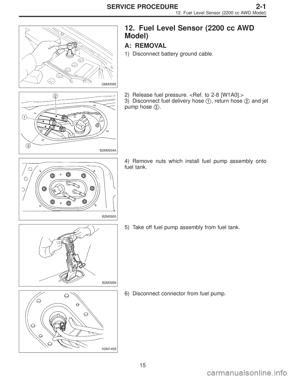
12. Fuel Level Sensor (2200 cc AWD
Model)
A: REMOVAL
1) Disconnect battery ground cable.
B2M0954A
2) Release fuel pressure.
3) Disconnect fuel delivery hose�
1, return hose�2and jet
pump hose�
3.
B2M0955
4) Remove nuts which install fuel pump assembly onto
fuel tank.
B2M0956
5) Take off fuel pump assembly from fuel tank.
H2M1459
6) Disconnect connector from fuel pump.
15
2-1SERVICE PROCEDURE
12. Fuel Level Sensor (2200 cc AWD Model)
Page 244 of 3342
 Remove two screws fixing bracket on fuel pump assem-
bly.
H2M1461A
8) Remove one screw fixing fuel level sensor on bracket.
9) Remove fuel level sensor from fuel pump assembly.
B2M0955A
B:")
H2M1460
7) Remove two screws fixing bracket on fuel pump assem-
bly.
H2M1461A
8) Remove one screw fixing fuel level sensor on bracket.
9) Remove fuel level sensor from fuel pump assembly.
B2M0955A
B: INSTALLATION
CAUTION:
Leave fuel filler cap open when tightening nuts, to pre-
vent fuel from flowing out through fuel delivery and
return pipes. Close fuel filler cap after tightening nuts.
Installation is in the reverse order of removal. Do the fol-
lowing:
(1) Always use new gaskets.
(2) Ensure sealing portion is free from fuel or foreign
particles before installation.
(3) Tighten nuts in numerical sequence shown in Fig-
ure to specified torque.
Tightening torque:
4.4±1.5 N⋅m (0.45±0.15 kg-m, 3.3±1.1 ft-lb)
B2M0968
13. Air Filter (2200 cc AWD Model)
A: REMOVAL AND INSTALLATION
1) Remove canister.
2) Remove two hoses from air filter.
3) Remove flange nut from bracket.
4) Installation is in the reverse order of removal.
16
2-1SERVICE PROCEDURE
12. Fuel Level Sensor (2200 cc AWD Model) - 13. Air Filter (2200 cc AWD Model)
Page 245 of 3342
 Remove two screws fixing bracket on fuel pump assem-
bly.
H2M1461A
8) Remove one screw fixing fuel level sensor on bracket.
9) Remove fuel level sensor from fuel pump assembly.
B2M0955A
B:")
H2M1460
7) Remove two screws fixing bracket on fuel pump assem-
bly.
H2M1461A
8) Remove one screw fixing fuel level sensor on bracket.
9) Remove fuel level sensor from fuel pump assembly.
B2M0955A
B: INSTALLATION
CAUTION:
Leave fuel filler cap open when tightening nuts, to pre-
vent fuel from flowing out through fuel delivery and
return pipes. Close fuel filler cap after tightening nuts.
Installation is in the reverse order of removal. Do the fol-
lowing:
(1) Always use new gaskets.
(2) Ensure sealing portion is free from fuel or foreign
particles before installation.
(3) Tighten nuts in numerical sequence shown in Fig-
ure to specified torque.
Tightening torque:
4.4±1.5 N⋅m (0.45±0.15 kg-m, 3.3±1.1 ft-lb)
B2M0968
13. Air Filter (2200 cc AWD Model)
A: REMOVAL AND INSTALLATION
1) Remove canister.
2) Remove two hoses from air filter.
3) Remove flange nut from bracket.
4) Installation is in the reverse order of removal.
16
2-1SERVICE PROCEDURE
12. Fuel Level Sensor (2200 cc AWD Model) - 13. Air Filter (2200 cc AWD Model)
Page 249 of 3342
 After warming-up the engine, turn ignition switch to
OFF.
2) Make sure that the battery is fully charged.
3) Remove all the spark plugs.
4) Dis")
4. Engine Compression
A: MEASUREMENT
1. 2200 cc MODEL
1) After warming-up the engine, turn ignition switch to
OFF.
2) Make sure that the battery is fully charged.
3) Remove all the spark plugs.
4) Disconnect connectors from fuel injectors.
5) Fully open throttle valve.
6) Check the starter motor for satisfactory performance
and operation.
G2M0098
7) Hold the compression gauge tight against the spark
plug hole.
CAUTION:
When using a screw-in type compression gauge, the
screw (put into cylinder head spark plug hole) should
be less than 18 mm (0.71 in) long.
8) Crank the engine by means of the starter motor, and
read the maximum value on the gauge when the pointer is
steady.
9) Perform at least two measurements per cylinder, and
make sure that the values are correct.
Compression (200—300 rpm and fully open throttle):
Standard
1,079—1,275 kPa
(11.0—13.0 kg/cm
2, 156—185 psi)
Limit
883 kPa (9.0 kg/cm
2, 128 psi)
Difference between cylinders
196 kPa (2.0 kg/cm
2, 28 psi)
2. 2500 cc MODEL
CAUTION:
After warming-up, engine becomes very hot. Be care-
ful not to burn yourself during measurement.
1) After warming-up the engine, turn ignition switch to
OFF.
2) Make sure that the battery is fully charged.
3) Remove all the spark plugs.
[W3E0].>
4) Disconnect connectors from fuel injectors.
4
2-2
4. Engine Compression
Page 252 of 3342
G2M0088
6. Engine Oil Pressure
A: MEASUREMENT
1) Remove generator from bracket.
(1) Disconnect connector and terminal from generator.
G2M0089
(2) Remove V-belt cover.
(3) Loosen lock bolt and slider bolt, and remove V-belt
for generator.
G2M0090
(4) Remove generator lock bolt.
(5) Remove bolt which install generator on bracket.
G2M0091
2) Disconnect connector from oil pressure switch.
3) Remove oil pressure switch from engine cylinder block.
7
2-2
6. Engine Oil Pressure
 Disconnect connector from fuel tank pressure sensor.
4) Remove bolts which install fuel tank pressure sensor
bracket on body.
B2M0961
5) Disconnect hose from fuel tank pressure sensor.
6) R")
 Disconnect connector from fuel tank pressure sensor.
4) Remove bolts which install fuel tank pressure sensor
bracket on body.
B2M0961
5) Disconnect hose from fuel tank pressure sensor.
6) R")
![SUBARU LEGACY 1997 Service Repair Manual G6M0095
11. Vent Control Solenoid Valve (2200
cc AWD Model)
A: REMOVAL
1) Disconnect battery ground cable.
B2M0964
2) Lift-up the vehicle.
3) Remove canister. <Ref. to 2-1 [W3A2].>
4) Disconnect two h](/manual-img/17/57434/w960_57434-240.png "SUBARU LEGACY 1997 Service Repair Manual G6M0095
11. Vent Control Solenoid Valve (2200
cc AWD Model)
A: REMOVAL
1) Disconnect battery ground cable.
B2M0964
2) Lift-up the vehicle.
3) Remove canister. <Ref. to 2-1 [W3A2].>
4) Disconnect two h")
 Remove generator from bracket.
(1) Disconnect connector and terminal from generator.
G2M0089
(2) Remove V-belt cover.
(3) Loosen lock bolt and slider b")